
Service Manual
Page 6
... the print cartridges 33 HP policy on non-HP supplies 33 HP anti-counterfeit website 33 Cleaning the printer ...34 To clean the printer at the printer 34 To clean the fuser using HP Toolbox 35 Cleaning spilled toner ...35 Calibrating the printer ...36 To calibrate the printer at the printer 36 To calibrate the printer from the HP Toolbox 36 4 Operational theory...
... the print cartridges 33 HP policy on non-HP supplies 33 HP anti-counterfeit website 33 Cleaning the printer ...34 To clean the printer at the printer 34 To clean the fuser using HP Toolbox 35 Cleaning spilled toner ...35 Calibrating the printer ...36 To calibrate the printer at the printer 36 To calibrate the printer from the HP Toolbox 36 4 Operational theory...

Service Manual
Page 7
General timing chart ...58 Printer calibration ...59 5 Removal and replacement Overview...62 Service approach...63 Pre-service procedures...63 Removal and replacement procedures 64 Print cartridge replacement 64 ETB removal and replacement 66 Fuser removal and replacement 74 Formatter removal and replacement 82 DC controller removal and ......98 Clearing jams ...99 Paper path...99 Common causes of paper jams 100 Where to look for jams...101 Jams inside the printer...102 Input jams...103 Tray 1...103 Tray 2...104 Output jams...104 Jams in the top bin 104 Pickup delay jam 105 Pickup...
General timing chart ...58 Printer calibration ...59 5 Removal and replacement Overview...62 Service approach...63 Pre-service procedures...63 Removal and replacement procedures 64 Print cartridge replacement 64 ETB removal and replacement 66 Fuser removal and replacement 74 Formatter removal and replacement 82 DC controller removal and ......98 Clearing jams ...99 Paper path...99 Common causes of paper jams 100 Where to look for jams...101 Jams inside the printer...102 Input jams...103 Tray 1...103 Tray 2...104 Output jams...104 Jams in the top bin 104 Pickup delay jam 105 Pickup...

Service Manual
Page 8
...counts and serial number 127 Cleaning the ETB...127 Troubleshooting tools...128 Printer pages and reports 128 Demo page...128 Configuration page 129 Event log...131 Supplies Status page 131 Fuser cleaning page 132 Print quality troubleshooting pages 132 Control panel messages (error...the factory-set defaults 138 General print quality issues 138 Solving issues with color documents 142 HP Toolbox...1. 44 HP Toolbox...144 To view HP Toolbox 144 Troubleshooting tab 144 Print quality troubleshooting pages 144 Printer calibration...144 Cleaning page...144 Configuration page...145 vi ENWW
...counts and serial number 127 Cleaning the ETB...127 Troubleshooting tools...128 Printer pages and reports 128 Demo page...128 Configuration page 129 Event log...131 Supplies Status page 131 Fuser cleaning page 132 Print quality troubleshooting pages 132 Control panel messages (error...the factory-set defaults 138 General print quality issues 138 Solving issues with color documents 142 HP Toolbox...1. 44 HP Toolbox...144 To view HP Toolbox 144 Troubleshooting tab 144 Print quality troubleshooting pages 144 Printer calibration...144 Cleaning page...144 Configuration page...145 vi ENWW

Service Manual
Page 11
List of 3) ...171 Control panel assembly ...175 Main drive assembly ...177 Fuser assembly ...181 PCB assembly location Tray 2 ...185 Tray 2 input tray (cassette) ...187 ENWW ix HP Color LaserJet 2600n printer software 11 Envelope specifications...15 Envelope size ranges...16 Tray 1 and Tray 2 specifications...17 ... issues...123 Configuration page...129 Supplies Status page...131 Status log only messages...137 General print quality issues...138 Color document issues...142 Repetitive image defects...147 Available replaceable parts ...150 Technical support Web sites ...152 Accessories ...152...
List of 3) ...171 Control panel assembly ...175 Main drive assembly ...177 Fuser assembly ...181 PCB assembly location Tray 2 ...185 Tray 2 input tray (cassette) ...187 ENWW ix HP Color LaserJet 2600n printer software 11 Envelope specifications...15 Envelope size ranges...16 Tray 1 and Tray 2 specifications...17 ... issues...123 Configuration page...129 Supplies Status page...131 Status log only messages...137 General print quality issues...138 Color document issues...142 Repetitive image defects...147 Available replaceable parts ...150 Technical support Web sites ...152 Accessories ...152...

Service Manual
Page 13
... 6-3 Figure 6-4 Figure 7-1 Figure 7-2 Figure 7-3 Figure 7-4 Figure 7-5 Figure 7-6 Figure 7-7 Figure 7-8 Figure 7-9 Figure 7-10 HP Color LaserJet 2600n printer...3 Front view (shown with optional Tray 3 6 Back and side view...7 Transfer belt (ETB) and print cartridges 7 Model and serial...side-seam construction 16 Printer dimensions ...22 Package contents ...24 Engine control system ...39 Image formation system ...42 Image formation process ...43 Latent image formation ...45 Laser beam exposure ...45......170 Control panel assembly ...174 Main drive assembly ...176 Fuser assembly ...180 ENWW xi
... 6-3 Figure 6-4 Figure 7-1 Figure 7-2 Figure 7-3 Figure 7-4 Figure 7-5 Figure 7-6 Figure 7-7 Figure 7-8 Figure 7-9 Figure 7-10 HP Color LaserJet 2600n printer...3 Front view (shown with optional Tray 3 6 Back and side view...7 Transfer belt (ETB) and print cartridges 7 Model and serial...side-seam construction 16 Printer dimensions ...22 Package contents ...24 Engine control system ...39 Image formation system ...42 Image formation process ...43 Latent image formation ...45 Laser beam exposure ...45......170 Control panel assembly ...174 Main drive assembly ...176 Fuser assembly ...180 ENWW xi

Service Manual
Page 30
... 14 inches) Envelopes with double side-seams Double side-seam construction has vertical seams at both ends of the printer. Be sure the seam extends all the way to the corner of the envelope as illustrated below. 1 ...likely to seal must use adhesives that are compatible with the heat and pressure in the printer. The extra flaps and strips might cause wrinkling, creasing, or even jams and might ... Condition: Envelopes should lie flat with less than one flap that folds over to wrinkle. This printer fusing temperature is 210°C (410°F). ■ Size: Use only envelopes that are ...
... 14 inches) Envelopes with double side-seams Double side-seam construction has vertical seams at both ends of the printer. Be sure the seam extends all the way to the corner of the envelope as illustrated below. 1 ...likely to seal must use adhesives that are compatible with the heat and pressure in the printer. The extra flaps and strips might cause wrinkling, creasing, or even jams and might ... Condition: Envelopes should lie flat with less than one flap that folds over to wrinkle. This printer fusing temperature is 210°C (410°F). ■ Size: Use only envelopes that are ...
Service Manual
Page 43
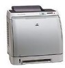
After a short time, the control panel should display Ready. For more information about using non-HP print cartridges, see To clean the printer at the printer or To clean the fuser using a non-HP print cartridge, check the printer control panel for the printer, the control panel will automatically print. NOTE When replacing or changing a black print cartridge...
After a short time, the control panel should display Ready. For more information about using non-HP print cartridges, see To clean the printer at the printer or To clean the fuser using a non-HP print cartridge, check the printer control panel for the printer, the control panel will automatically print. NOTE When replacing or changing a black print cartridge...

Service Manual
Page 48
...page will be automatically generated prior to HP Toolbox, HP recommends cleaning the paper path by using HP Toolbox. To manually generate a cleaning page, see To clean the fuser using HP Toolbox. Use the following procedure to clean the printer at the printer NOTE If you have access to calibration.... A page feeds through the printer slowly. This printer has a cleaning mode that can cause print-quality ...
...page will be automatically generated prior to HP Toolbox, HP recommends cleaning the paper path by using HP Toolbox. To manually generate a cleaning page, see To clean the fuser using HP Toolbox. Use the following procedure to clean the printer at the printer NOTE If you have access to calibration.... A page feeds through the printer slowly. This printer has a cleaning mode that can cause print-quality ...
Service Manual
Page 49
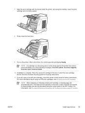
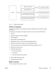
...Make sure that the printer is turned on and in Tray 2 or optional Tray 3. 5 Remove the page that print immediately after a paper jam has occurred, some toner might remain on the rollers and guides inside the printer. ENWW Cleaning the printer 35 To clean the fuser using HP Toolbox NOTE Use the... following procedure to clean the fuser using the HP Toolbox.
...Make sure that the printer is turned on and in Tray 2 or optional Tray 3. 5 Remove the page that print immediately after a paper jam has occurred, some toner might remain on the rollers and guides inside the printer. ENWW Cleaning the printer 35 To clean the fuser using HP Toolbox NOTE Use the... following procedure to clean the fuser using the HP Toolbox.
Service Manual
Page 53
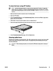
...motor, pickup motor, and fuser/delivery motor 7 Fuser heater initial drive by controlling fuser temperature targeting for 100°?C 8 Initial drive for possible malfunctions. The following is the sequence from when the printer is for the purpose of the printer initialization and checking for scanner ...motor 9 Failure/Abnormality check ● Detect scanner failure ● Fuser failure ● Door open during the above periods 10 ...
...motor, pickup motor, and fuser/delivery motor 7 Fuser heater initial drive by controlling fuser temperature targeting for 100°?C 8 Initial drive for possible malfunctions. The following is the sequence from when the printer is for the purpose of the printer initialization and checking for scanner ...motor 9 Failure/Abnormality check ● Detect scanner failure ● Fuser failure ● Door open during the above periods 10 ...

Service Manual
Page 54
... condition. Failure detection Yes No No Yes Main motor failure detection The CPU determines the main motor failure, stops the printer, and notifies the formatter of the /MAINMFG signal stays at an irregular interval for approximately 10 seconds and longer during fan...Purpose Type Main motor (M1) Drive ETB belt, photosensitive drum and developing cylinder DC motor Fuser/delivery motor (M2) Drive fuser pressure roller, delivery roller and automatic release of fuser pressure Stepping motor Pickup motor (M3) Drive pickup roller and registration roller Stepping motor Fan (...
... condition. Failure detection Yes No No Yes Main motor failure detection The CPU determines the main motor failure, stops the printer, and notifies the formatter of the /MAINMFG signal stays at an irregular interval for approximately 10 seconds and longer during fan...Purpose Type Main motor (M1) Drive ETB belt, photosensitive drum and developing cylinder DC motor Fuser/delivery motor (M2) Drive fuser pressure roller, delivery roller and automatic release of fuser pressure Stepping motor Pickup motor (M3) Drive pickup roller and registration roller Stepping motor Fan (...

Service Manual
Page 58
...image formation is described here. Step 3: Development 3 Transfer stage Transfers a toner image on paper. Step 4: Transfer Step 5: Separation 4 Fuser stage Fuses the toner image on the photosensitive drum onto paper. Step 7: ETB cleaning Latent image formation This stage consists of two steps and... toner image is called an "electrostatic latent image" as it is removed from the exposed area. Step 1: Primary charging Step 2: Laser beam exposure 2 Developing stage Makes the electrostatic latent image on paper as it goes through each process. The print process can be broadly...
...image formation is described here. Step 3: Development 3 Transfer stage Transfers a toner image on paper. Step 4: Transfer Step 5: Separation 4 Fuser stage Fuses the toner image on the photosensitive drum onto paper. Step 7: ETB cleaning Latent image formation This stage consists of two steps and... toner image is called an "electrostatic latent image" as it is removed from the exposed area. Step 1: Primary charging Step 2: Laser beam exposure 2 Developing stage Makes the electrostatic latent image on paper as it goes through each process. The print process can be broadly...

Service Manual
Page 63
... image is separated from the back side of M, C, Y, and K, and forms one toner image overlaying one color's image on -demand fuser method in order of the paper. This printer utilizes the ceramic heater with the electrostatic eliminator in this step. The toner on the photosensitive drum surface is transferred... easily by the static electricity. The paper and the toner on the back side of the paper is transferred in this stage. Each color's toner image is decreased with lower heat capacity, which warms up quickly, does ENWW Image formation system 49 Separation stage Figure 4-10...
... image is separated from the back side of M, C, Y, and K, and forms one toner image overlaying one color's image on -demand fuser method in order of the paper. This printer utilizes the ceramic heater with the electrostatic eliminator in this step. The toner on the photosensitive drum surface is transferred... easily by the static electricity. The paper and the toner on the back side of the paper is transferred in this stage. Each color's toner image is decreased with lower heat capacity, which warms up quickly, does ENWW Image formation system 49 Separation stage Figure 4-10...

Service Manual
Page 64
As for the printer, the DC positive bias is applied to the fuser pressure roller, so the transferred toner stays harder on the paper and toner scattering to the fuser film (offset) is prevented. 50 Chapter 4 Operational theory ENWW not require the power supply during STBY mode, and saves energy.
As for the printer, the DC positive bias is applied to the fuser pressure roller, so the transferred toner stays harder on the paper and toner scattering to the fuser film (offset) is prevented. 50 Chapter 4 Operational theory ENWW not require the power supply during STBY mode, and saves energy.

Service Manual
Page 65
..., consists of paper ■ SR9 detects the fuser pressure roller alienation in the fuser ■ SR8 detects the paper width The figure below illustrates the motors, solenoids, and sensors. ENWW Pickup and feed system 51 This printer has two pickup sources: the cassette and the manual...(SR2): detects the presence of paper in the cassette ■ DC controller controls the following to drive each feed roller: ■ Main motor (M1) ■ Fuser/delivery motor (M2) ■ Pickup motor (M3) ■ Solenoid (SL1) ■ Solenoid (SL2) ■ Solenoid (SL3) ■ Photo sensors: &#...
..., consists of paper ■ SR9 detects the fuser pressure roller alienation in the fuser ■ SR8 detects the paper width The figure below illustrates the motors, solenoids, and sensors. ENWW Pickup and feed system 51 This printer has two pickup sources: the cassette and the manual...(SR2): detects the presence of paper in the cassette ■ DC controller controls the following to drive each feed roller: ■ Main motor (M1) ■ Fuser/delivery motor (M2) ■ Pickup motor (M3) ■ Solenoid (SL1) ■ Solenoid (SL2) ■ Solenoid (SL3) ■ Photo sensors: &#...

Service Manual
Page 67
... of the manual feed slot pickup. 1 If paper is detected by the drive of paper in the manual feed slot is set into the printer. Figure 4-13 Skew correction illustrates how skewed paper is corrected by the registration shutter when the paper is fed into the...temperature rise at the end of shorter than 190 mm (7.5 inches). This printer does not have a pickup roller in the paper transport path to the fuser/delivery stage. Skew correction by the registration shutter If the paper fed into the printer. 2 Toner is transfered to the paper from the photosensitive drum and then...
... of the manual feed slot pickup. 1 If paper is detected by the drive of paper in the manual feed slot is set into the printer. Figure 4-13 Skew correction illustrates how skewed paper is corrected by the registration shutter when the paper is fed into the...temperature rise at the end of shorter than 190 mm (7.5 inches). This printer does not have a pickup roller in the paper transport path to the fuser/delivery stage. Skew correction by the registration shutter If the paper fed into the printer. 2 Toner is transfered to the paper from the photosensitive drum and then...

Service Manual
Page 68
...the formatter of the CPU. The check timing is present at the sensor at the check timing. Figure 4-13 Skew correction Jam detection This printer is provided with the following paper detection sensors to detect the presence of paper and whether or not the paper feed is operating normally. ...■ Registration paper sensor (SR1) ■ Pre-fuser paper sensor (SR5) ■ Fuser delivery paper sensor (SR4) The CPU determines a paper jam by checking whether or not paper is stored in the memory of a jam ...
...the formatter of the CPU. The check timing is present at the sensor at the check timing. Figure 4-13 Skew correction Jam detection This printer is provided with the following paper detection sensors to detect the presence of paper and whether or not the paper feed is operating normally. ...■ Registration paper sensor (SR1) ■ Pre-fuser paper sensor (SR5) ■ Fuser delivery paper sensor (SR4) The CPU determines a paper jam by checking whether or not paper is stored in the memory of a jam ...

Service Manual
Page 77
...Field Service on this printer. ■ Fuser ■ ETB ■ DC Controller ■ Formatter ■ Control Panel display If troubleshooting or a Control Panel message determines that the failure is not associated with one of these parts, do not attempt to repair the printer, but replace the ... 30 minutes, which includes troubleshooting, teardown, and repair. ENWW Service approach 63 For more time should not be made and the printer should be replaced, refer to the Critical error messages table and the Replaceable parts table. The following are the major internal assemblies ...
...Field Service on this printer. ■ Fuser ■ ETB ■ DC Controller ■ Formatter ■ Control Panel display If troubleshooting or a Control Panel message determines that the failure is not associated with one of these parts, do not attempt to repair the printer, but replace the ... 30 minutes, which includes troubleshooting, teardown, and repair. ENWW Service approach 63 For more time should not be made and the printer should be replaced, refer to the Critical error messages table and the Replaceable parts table. The following are the major internal assemblies ...

Service Manual
Page 88
1 Tabs Fuser removal and replacement Use the following procedure to remove the fuser. 1 Unplug the power cable. 2 Remove the paper delivery tray assembly (RM1-1859-000CN). 74 Chapter 5 Removal and replacement ENWW
1 Tabs Fuser removal and replacement Use the following procedure to remove the fuser. 1 Unplug the power cable. 2 Remove the paper delivery tray assembly (RM1-1859-000CN). 74 Chapter 5 Removal and replacement ENWW

Service Manual
Page 91
9 Lift up and remove the face-down cover (RC1-5173-000CN). 10 Remove the output tray by releasing the tabs. 1 Release tabs 11 Unplug the harness from the fuser motor. ENWW Removal and replacement procedures 77
9 Lift up and remove the face-down cover (RC1-5173-000CN). 10 Remove the output tray by releasing the tabs. 1 Release tabs 11 Unplug the harness from the fuser motor. ENWW Removal and replacement procedures 77


