
Service Manual
Page 52
The purposes of each period, from the formatter. The engine control system coordinates all printer functions. It drives the laser/scanner system, the image formation system, and the pickup and feed system. The engine control system contains the following components: ■ DC controller PCB &#... initial drive. potential and to print. Or, from the formatter, and to clean the ETB. To keep the printer ready to clean the ETB. To form the image on the photosensitive drum based on . From the end of LSTR until power-off until the developing high-voltage is turned on the...
The purposes of each period, from the formatter. The engine control system coordinates all printer functions. It drives the laser/scanner system, the image formation system, and the pickup and feed system. The engine control system contains the following components: ■ DC controller PCB &#... initial drive. potential and to print. Or, from the formatter, and to clean the ETB. To keep the printer ready to clean the ETB. To form the image on the photosensitive drum based on . From the end of LSTR until power-off until the developing high-voltage is turned on the...

Service Manual
Page 54
... become the specified interval after once it encounters the following condition. Table 4-2 Motor specifications Name Motor Purpose Type Main motor (M1) Drive ETB belt, photosensitive drum and developing cylinder DC motor Fuser/delivery motor (M2) Drive fuser pressure roller, delivery roller and automatic release of fuser pressure Stepping motor Pickup motor...) does not become the specified interval. Failure detection Yes No No Yes Main motor failure detection The CPU determines the main motor failure, stops the printer, and notifies the formatter of rotation CW CW/CCW CW -
... become the specified interval after once it encounters the following condition. Table 4-2 Motor specifications Name Motor Purpose Type Main motor (M1) Drive ETB belt, photosensitive drum and developing cylinder DC motor Fuser/delivery motor (M2) Drive fuser pressure roller, delivery roller and automatic release of fuser pressure Stepping motor Pickup motor...) does not become the specified interval. Failure detection Yes No No Yes Main motor failure detection The CPU determines the main motor failure, stops the printer, and notifies the formatter of rotation CW CW/CCW CW -

Service Manual
Page 58
...goes through each process. Step 1: Primary charging Step 2: Laser beam exposure 2 Developing stage Makes the electrostatic latent image on the photosensitive drum. Step 3: Development 3 Transfer stage Transfers a toner image on the photosensitive drum. The following figure illustrates the stages and steps of ...formed on paper as follows. 1 Electrostatic latent image formation stage Forms an electrostatic latent image on the photosensitive drum surface visible by the laser beam and is described here. The image with 7 steps. Step 7: ETB cleaning Latent image formation This ...
...goes through each process. Step 1: Primary charging Step 2: Laser beam exposure 2 Developing stage Makes the electrostatic latent image on the photosensitive drum. Step 3: Development 3 Transfer stage Transfers a toner image on the photosensitive drum. The following figure illustrates the stages and steps of ...formed on paper as follows. 1 Electrostatic latent image formation stage Forms an electrostatic latent image on the photosensitive drum surface visible by the laser beam and is described here. The image with 7 steps. Step 7: ETB cleaning Latent image formation This ...

Service Manual
Page 59
... motor, and so forth. This printer utilizes the projection development method by applying the toner in this process. Figure 4-4 Latent image formation Laser/scanner system The laser/scanner system forms latent images on the photosensitive drum surface is visualized by the non-magnetic..., singlecomponent toner. ENWW Image formation system 45 Figure 4-5 Laser beam exposure Developing stage The electrostatic latent...
... motor, and so forth. This printer utilizes the projection development method by applying the toner in this process. Figure 4-4 Latent image formation Laser/scanner system The laser/scanner system forms latent images on the photosensitive drum surface is visualized by the non-magnetic..., singlecomponent toner. ENWW Image formation system 45 Figure 4-5 Laser beam exposure Developing stage The electrostatic latent...

Service Manual
Page 60
The area of the photosensitive drum, where the laser beam is exposed, has higher potential than the toner, which is called the projection development and it visualizes the electrostatic latent image on the IMAGE ... print quality and also prevents toner scattering. This printer is applied the AC bias in order to changes of the output image. The developing cylinder is able to adjust the image density by the potential difference between the cylinder and the photosensitive drum surface according to make the toner jump easier onto...
The area of the photosensitive drum, where the laser beam is exposed, has higher potential than the toner, which is called the projection development and it visualizes the electrostatic latent image on the IMAGE ... print quality and also prevents toner scattering. This printer is applied the AC bias in order to changes of the output image. The developing cylinder is able to adjust the image density by the potential difference between the cylinder and the photosensitive drum surface according to make the toner jump easier onto...
Service Manual
Page 61
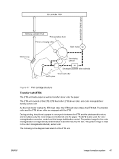
..., the picked up paper is conveyed in between the ETB and the photosensitive drum, and simultaneously the toner image is read in the color misregistration/density sensor unit. The ETB is also used for the color misregistration or image density determination is the diagrammatic sketch of the ETB, ETB ...the paper. As the main motor rotates the ETB feed roller, the ETB feed roller rotates the ETB belt. The pattern image for color misregistration corrective control and the image stabilization control. The following is transferred onto the belt. The transfer roller and the ETB driven roller...
..., the picked up paper is conveyed in between the ETB and the photosensitive drum, and simultaneously the toner image is read in the color misregistration/density sensor unit. The ETB is also used for the color misregistration or image density determination is the diagrammatic sketch of the ETB, ETB ...the paper. As the main motor rotates the ETB feed roller, the ETB feed roller rotates the ETB belt. The pattern image for color misregistration corrective control and the image stabilization control. The following is transferred onto the belt. The transfer roller and the ETB driven roller...
Service Manual
Page 62
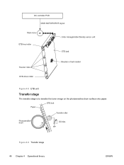
Figure 4-9 Transfer stage 48 Chapter 4 Operational theory ENWW Figure 4-8 ETB unit Transfer stage The transfer stage is to transfer the toner image on the photosensitive drum surface onto paper.
Figure 4-9 Transfer stage 48 Chapter 4 Operational theory ENWW Figure 4-8 ETB unit Transfer stage The transfer stage is to transfer the toner image on the photosensitive drum surface onto paper.

Service Manual
Page 63
... ENWW Image formation system 49 The static charge on it is only attracted to the paper by its elasticity (Curvature Separation). This printer utilizes the ceramic heater with the electrostatic eliminator in order to stablize the feeding operation and prevent the crescent spots of printing image ...through the transfer stage can be a permanent image. Each color's toner image is transferred in order of the paper. Fusing stage The toner image is fused onto the paper in this step. The toner on the photosensitive drum surface is transferred onto the paper according to the positive...
... ENWW Image formation system 49 The static charge on it is only attracted to the paper by its elasticity (Curvature Separation). This printer utilizes the ceramic heater with the electrostatic eliminator in order to stablize the feeding operation and prevent the crescent spots of printing image ...through the transfer stage can be a permanent image. Each color's toner image is transferred in order of the paper. Fusing stage The toner image is fused onto the paper in this step. The toner on the photosensitive drum surface is transferred onto the paper according to the positive...

Service Manual
Page 67
... sequence of paper only that is inserted into the manual feed slot and then into the printer. This printer does not have a pickup roller in the paper transport path to the paper from the photosensitive drum and then the paper is a paper width sensor in the manual feed slot. The presence... of paper feed. 1 Paper skew is corrected by the registration shutter when the paper is fed into the printer is detected by the registration shutter If ...
... sequence of paper only that is inserted into the manual feed slot and then into the printer. This printer does not have a pickup roller in the paper transport path to the paper from the photosensitive drum and then the paper is a paper width sensor in the manual feed slot. The presence... of paper feed. 1 Paper skew is corrected by the registration shutter when the paper is fed into the printer is detected by the registration shutter If ...

Service Manual
Page 177
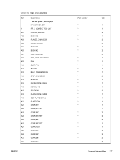
... 54T 13 SPRING, TENSION 14 SPRING, COMPRESSION 15 LEFT INTERNAL COVER ASS'Y 16 GUIDE, CARTRIDGE, RIGHT 17 HOLDER, DRUM 18 BUSHING 19 PLATE, PRESSURE, RIGHT 20 BUSHING 21 GUIDE, CASSETTE, REAR RIGHT 22 GUIDE, CASSETTE, FRONT RIGHT... 26 SPRING, TORSION 27 SCREW, RS, M3X8 27 SCREW, RS, M3X8 27 SCREW, RS, M3X8 27 SCREW, RS, M3X8 28 GUIDE, CARTRIDGE, LEFT 29 HOLDER, DRUM ENWW Part number Qty * RF * 1 * 1 * 1 * 1 * 1 * 1 * 1 * 1 * 1 * 1 * 1 * 1 * 2 * 1 * 1 * 1 * 1 * 1 * 4 * 4 * 1 * 1 * 2 * 4 * 2 ...
... 54T 13 SPRING, TENSION 14 SPRING, COMPRESSION 15 LEFT INTERNAL COVER ASS'Y 16 GUIDE, CARTRIDGE, RIGHT 17 HOLDER, DRUM 18 BUSHING 19 PLATE, PRESSURE, RIGHT 20 BUSHING 21 GUIDE, CASSETTE, REAR RIGHT 22 GUIDE, CASSETTE, FRONT RIGHT... 26 SPRING, TORSION 27 SCREW, RS, M3X8 27 SCREW, RS, M3X8 27 SCREW, RS, M3X8 27 SCREW, RS, M3X8 28 GUIDE, CARTRIDGE, LEFT 29 HOLDER, DRUM ENWW Part number Qty * RF * 1 * 1 * 1 * 1 * 1 * 1 * 1 * 1 * 1 * 1 * 1 * 1 * 2 * 1 * 1 * 1 * 1 * 1 * 4 * 4 * 1 * 1 * 2 * 4 * 2 ...
Service Manual
Page 191
CONNECT PCB UNIT A01 COLLAR, SPRING A02 BUSHING A03 FLANGE, CAM GEAR A04 COVER, DRUM A05 BUSHING A06 BUSHING A07 CAM, RELEASE A08 ROD, RELEASE, RIGHT A09 FAN A10 DUCT, FAN A11 PULLEY A12 BELT, TRANSMISSION A13 STOP, CAM GEAR ...
CONNECT PCB UNIT A01 COLLAR, SPRING A02 BUSHING A03 FLANGE, CAM GEAR A04 COVER, DRUM A05 BUSHING A06 BUSHING A07 CAM, RELEASE A08 ROD, RELEASE, RIGHT A09 FAN A10 DUCT, FAN A11 PULLEY A12 BELT, TRANSMISSION A13 STOP, CAM GEAR ...

Service Manual
Page 192
Ref Description A32 GEAR, 27T/64T A33 GEAR, 64T A34 GEAR, 54T A35 GEAR, 54T A36 GEAR, 18T A37 SPRING, COMPRESSION A38 SPRING, COMPRESSION A39 SPRING, TENSION A40 SHAFT, DRUM GEAR A41 CONNECTOR, 2P A42 CONNECTOR, SNAP TIGHT, BK A43 CLIP, CABLE A44 CLIP, EDGE A45 SCREW, RS, M3X8 A46 SCREW, TAPPING,TRUSS HEAD,M4X8 A47 SE RING A48 RING, E Part number Qty * 1 * 1 * 1 * 1 * 1 * 4 * 2 * 2 * 4 * 2 * 2 * 5 * 1 * 18 * 2 * 1 * 2 178 Chapter 7 Parts and diagrams ENWW
Ref Description A32 GEAR, 27T/64T A33 GEAR, 64T A34 GEAR, 54T A35 GEAR, 54T A36 GEAR, 18T A37 SPRING, COMPRESSION A38 SPRING, COMPRESSION A39 SPRING, TENSION A40 SHAFT, DRUM GEAR A41 CONNECTOR, 2P A42 CONNECTOR, SNAP TIGHT, BK A43 CLIP, CABLE A44 CLIP, EDGE A45 SCREW, RS, M3X8 A46 SCREW, TAPPING,TRUSS HEAD,M4X8 A47 SE RING A48 RING, E Part number Qty * 1 * 1 * 1 * 1 * 1 * 4 * 2 * 2 * 4 * 2 * 2 * 5 * 1 * 18 * 2 * 1 * 2 178 Chapter 7 Parts and diagrams ENWW

Service Manual
Page 227
... PANEL PCB ASS'Y CONTROL PANEL PCB ASS'Y COVER, CASSETTE DUST COVER, CASSETTE DUST COVER, CASSETTE DUST COVER, CASSETTE, LEFT COVER, CASSETTE, RIGHT COVER, CONTROLLER COVER, DRUM Part number * * * * * * * * * * * * * * * * RM1-1983-000CN RM1-1983-000CN * * RC1-5200-000CN RC1-5200-000CN RC1-5200-000CN RC1-5184-000CN RC1-5188-000CN * * Table and...
... PANEL PCB ASS'Y CONTROL PANEL PCB ASS'Y COVER, CASSETTE DUST COVER, CASSETTE DUST COVER, CASSETTE DUST COVER, CASSETTE, LEFT COVER, CASSETTE, RIGHT COVER, CONTROLLER COVER, DRUM Part number * * * * * * * * * * * * * * * * RM1-1983-000CN RM1-1983-000CN * * RC1-5200-000CN RC1-5200-000CN RC1-5200-000CN RC1-5184-000CN RC1-5188-000CN * * Table and...

Service Manual
Page 233
..., REGISTRATION HIGH-VOLTAGE PCB ASS'Y HIGH-VOLTAGE PCB ASS'Y HOLDER, CABLE, LEFT HOLDER, CABLE, UPPER HOLDER, DC CABLE HOLDER, DRAWER HOLDER, DRAWER CONNECTOR HOLDER, DRUM HOLDER, DRUM HOLDER, FAN RETAINER HOLDER, MEMORY CONTROLLER HOLDER, PAD HOLDER, PAD HOLDER, PAD HOLDER, PAD HOLDER, PAD HOLDER, PAD HOLDER, PAPER PICKUP ROLLER HOLDER, PAPER PICKUP...
..., REGISTRATION HIGH-VOLTAGE PCB ASS'Y HIGH-VOLTAGE PCB ASS'Y HOLDER, CABLE, LEFT HOLDER, CABLE, UPPER HOLDER, DC CABLE HOLDER, DRAWER HOLDER, DRAWER CONNECTOR HOLDER, DRUM HOLDER, DRUM HOLDER, FAN RETAINER HOLDER, MEMORY CONTROLLER HOLDER, PAD HOLDER, PAD HOLDER, PAD HOLDER, PAD HOLDER, PAD HOLDER, PAD HOLDER, PAPER PICKUP ROLLER HOLDER, PAPER PICKUP...

Service Manual
Page 240
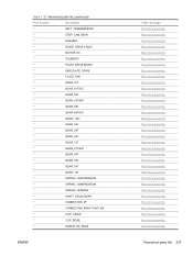
Table 7-22 Alphabetical parts list (continued) Description SE RING SEPARATION ASS'Y SEPARATION ASS'Y SHAFT, DRUM GEAR SHAFT, ETB DRIVE SHAFT, FACE-DOWN ROLLER SHAFT, FRONT DOOR SHAFT, FRONT DOOR ARM SHAFT, PAPER PICKUP DRIVE SHAFT, PAPER PICKUP DRIVE SHAFT, POSITIONING ...
Table 7-22 Alphabetical parts list (continued) Description SE RING SEPARATION ASS'Y SEPARATION ASS'Y SHAFT, DRUM GEAR SHAFT, ETB DRIVE SHAFT, FACE-DOWN ROLLER SHAFT, FRONT DOOR SHAFT, FRONT DOOR ARM SHAFT, PAPER PICKUP DRIVE SHAFT, PAPER PICKUP DRIVE SHAFT, POSITIONING ...

Service Manual
Page 246
..., FAN RETAINER * LATCH, LEFT * BUSHING * LATCH, RIGHT * LEVER, ETB RELEASE * FAN * GEAR, 54T * SPRING, TENSION * SPRING, COMPRESSION * LEFT INTERNAL COVER ASS'Y * GUIDE, CARTRIDGE, RIGHT * HOLDER, DRUM * BUSHING * PLATE, PRESSURE, RIGHT * BUSHING * GUIDE, CASSETTE, REAR RIGHT * GUIDE, CASSETTE, FRONT RIGHT * GEAR, 20T * GEAR, 36T * GEAR, 36T * SPRING, TORSION 232 Chapter 7 Parts and...
..., FAN RETAINER * LATCH, LEFT * BUSHING * LATCH, RIGHT * LEVER, ETB RELEASE * FAN * GEAR, 54T * SPRING, TENSION * SPRING, COMPRESSION * LEFT INTERNAL COVER ASS'Y * GUIDE, CARTRIDGE, RIGHT * HOLDER, DRUM * BUSHING * PLATE, PRESSURE, RIGHT * BUSHING * GUIDE, CASSETTE, REAR RIGHT * GUIDE, CASSETTE, FRONT RIGHT * GEAR, 20T * GEAR, 36T * GEAR, 36T * SPRING, TORSION 232 Chapter 7 Parts and...

Service Manual
Page 247
...number Description * SCREW, RS, M3X8 * SCREW, RS, M3X8 * SCREW, RS, M3X8 * SCREW, RS, M3X8 * GUIDE, CARTRIDGE, LEFT * HOLDER, DRUM * LINK, SHUTTER * PLATE, PRESSURE, LEFT * SPRING, TORSION * PLATE, SHAFT * ARM, OPEN/CLOSE * ARM, OPEN/CLOSE * SPRING, TORSION * ...ROD, LEFT * SPRING, GROUNDING * GUIDE, CASSETTE, FRONT LEFT * GUIDE, CASSETTE, REAR LEFT * RING, E * ARM, LASER SHUTTER * DUCT, FAN * SPRING, TENSION * MEMORY CONTROLLER PCB ASS'Y * DUCT, FAN, UPPER * DUCT, FAN, LOWER * HOLDER, MEMORY CONTROLLER * FLAG...
...number Description * SCREW, RS, M3X8 * SCREW, RS, M3X8 * SCREW, RS, M3X8 * SCREW, RS, M3X8 * GUIDE, CARTRIDGE, LEFT * HOLDER, DRUM * LINK, SHUTTER * PLATE, PRESSURE, LEFT * SPRING, TORSION * PLATE, SHAFT * ARM, OPEN/CLOSE * ARM, OPEN/CLOSE * SPRING, TORSION * ...ROD, LEFT * SPRING, GROUNDING * GUIDE, CASSETTE, FRONT LEFT * GUIDE, CASSETTE, REAR LEFT * RING, E * ARM, LASER SHUTTER * DUCT, FAN * SPRING, TENSION * MEMORY CONTROLLER PCB ASS'Y * DUCT, FAN, UPPER * DUCT, FAN, LOWER * HOLDER, MEMORY CONTROLLER * FLAG...

Service Manual
Page 250
CONNECT PCB UNIT * COLLAR, SPRING * BUSHING * FLANGE, CAM GEAR * COVER, DRUM * BUSHING * BUSHING * CAM, RELEASE * ROD, RELEASE, RIGHT * FAN * DUCT, FAN * PULLEY 236 Chapter 7 Parts and diagrams Table and page Internal components (3 of 3) Internal components (3 of 3) ...
CONNECT PCB UNIT * COLLAR, SPRING * BUSHING * FLANGE, CAM GEAR * COVER, DRUM * BUSHING * BUSHING * CAM, RELEASE * ROD, RELEASE, RIGHT * FAN * DUCT, FAN * PULLEY 236 Chapter 7 Parts and diagrams Table and page Internal components (3 of 3) Internal components (3 of 3) ...
Service Manual
Page 251
..., 86T * GEAR, 64T * GEAR, 64T * GEAR, 37T * GEAR, 27T/64T * GEAR, 64T * GEAR, 54T * GEAR, 54T * GEAR, 18T * SPRING, COMPRESSION * SPRING, COMPRESSION * SPRING, TENSION * SHAFT, DRUM GEAR * CONNECTOR, 2P * CONNECTOR, SNAP TIGHT, BK * CLIP, CABLE * CLIP, EDGE * SCREW, RS, M3X8 ENWW Table and page Main drive assembly Main drive assembly Main...
..., 86T * GEAR, 64T * GEAR, 64T * GEAR, 37T * GEAR, 27T/64T * GEAR, 64T * GEAR, 54T * GEAR, 54T * GEAR, 18T * SPRING, COMPRESSION * SPRING, COMPRESSION * SPRING, TENSION * SHAFT, DRUM GEAR * CONNECTOR, 2P * CONNECTOR, SNAP TIGHT, BK * CLIP, CABLE * CLIP, EDGE * SCREW, RS, M3X8 ENWW Table and page Main drive assembly Main drive assembly Main...


