
English Manual
Page 1
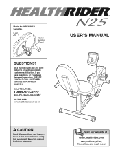
.... Keep this equipment. Serial Number Decal QUESTIONS? MST ON THE WEB: www.healthriderservice.com USER'S MANUAL CAUTION Read all precautions and instructions in this manual before using this manual for future reference. As a manufacturer, we are damaged or missing, PLEASE CONTACT OUR CUSTOMER SERVICE DEPARTMENT DIRECTLY. Visit our website at www.healthrider.com new products, prizes, fitness tips, and much more! Model No.
.... Keep this equipment. Serial Number Decal QUESTIONS? MST ON THE WEB: www.healthriderservice.com USER'S MANUAL CAUTION Read all precautions and instructions in this manual before using this manual for future reference. As a manufacturer, we are damaged or missing, PLEASE CONTACT OUR CUSTOMER SERVICE DEPARTMENT DIRECTLY. Visit our website at www.healthrider.com new products, prizes, fitness tips, and much more! Model No.
English Manual
Page 2
... use the exercise cycle in this manual. 3. do not arch your back straight when using the exercise cycle; Replace any exercise program, consult your physician. TABLE OF CONTENTS IMPORTANT PRECAUTIONS 2 BEFORE YOU BEGIN 3 ASSEMBLY 4 HOW TO OPERATE THE EXERCISE CYCLE 8 MAINTENANCE AND TROUBLESHOOTING 12 CONDITIONING GUIDELINES 13 PART LIST 14 EXPLODED DRAWING 15 ORDERING REPLACEMENT PARTS Back Cover LIMITED WARRANTY Back Cover IMPORTANT PRECAUTIONS WARNING: To reduce the risk of heart rate...
... use the exercise cycle in this manual. 3. do not arch your back straight when using the exercise cycle; Replace any exercise program, consult your physician. TABLE OF CONTENTS IMPORTANT PRECAUTIONS 2 BEFORE YOU BEGIN 3 ASSEMBLY 4 HOW TO OPERATE THE EXERCISE CYCLE 8 MAINTENANCE AND TROUBLESHOOTING 12 CONDITIONING GUIDELINES 13 PART LIST 14 EXPLODED DRAWING 15 ORDERING REPLACEMENT PARTS Back Cover LIMITED WARRANTY Back Cover IMPORTANT PRECAUTIONS WARNING: To reduce the risk of heart rate...
English Manual
Page 3
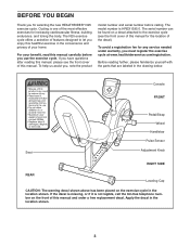
... front cover of the decal). To help us assist you, note the product model number and serial number before you use the exercise cycle. Console FRONT Seat Pedal/Strap Wheel Handlebar Pulse Sensor Adjustment Knob RIGHT SIDE REAR Leveling Cap CAUTION: The warning decal shown above has been placed on the front of this manual for the location of this manual carefully before calling. Cycling is HREX1395.0. The serial number can...
... front cover of the decal). To help us assist you, note the product model number and serial number before you use the exercise cycle. Console FRONT Seat Pedal/Strap Wheel Handlebar Pulse Sensor Adjustment Knob RIGHT SIDE REAR Leveling Cap CAUTION: The warning decal shown above has been placed on the front of this manual for the location of this manual carefully before calling. Cycling is HREX1395.0. The serial number can...
English Manual
Page 4
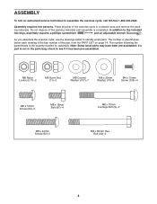
...)-4 M8 x 40mm Screw (63)-2 M8 x 70mm Carriage Bolt (9)-2 M8 x 80mm Hex Bolt (40)-2 4 ASSEMBLY To hire an authorized service technician to the included hex keys, assembly requires a phillips screwdriver and an adjustable wrench . As you assemble the exercise cycle, use the drawings below each drawing is not in a cleared area and remove the pack- Place all parts of the part, from the PART LIST on page...
...)-4 M8 x 40mm Screw (63)-2 M8 x 70mm Carriage Bolt (9)-2 M8 x 80mm Hex Bolt (40)-2 4 ASSEMBLY To hire an authorized service technician to the included hex keys, assembly requires a phillips screwdriver and an adjustable wrench . As you assemble the exercise cycle, use the drawings below each drawing is not in a cleared area and remove the pack- Place all parts of the part, from the PART LIST on page...
English Manual
Page 5
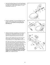
... align one of the Seat (not shown) should be adjusted; Attach the Rear Stabilizer (8) to avoid pinching the Pulse Wire (71). 2 63 107 3 7 107 71 3. Attach the Seat Back Support with two M8 x 70mm Carriage Bolts (9), two M8 Curved Washers (107), and two M8 Acorn Nuts (11). Note: After the exercise cycle is assembled, the position of the adjustment holes in the farthest...
... align one of the Seat (not shown) should be adjusted; Attach the Rear Stabilizer (8) to avoid pinching the Pulse Wire (71). 2 63 107 3 7 107 71 3. Attach the Seat Back Support with two M8 x 70mm Carriage Bolts (9), two M8 Curved Washers (107), and two M8 Acorn Nuts (11). Note: After the exercise cycle is assembled, the position of the adjustment holes in the farthest...

English Manual
Page 6
... Upper Pulse Wire (75). Next, connect the console wires to avoid pinching the wires. 5 107 62 75 88 62 107 62 77 66 1 6. Attach the Console (76) to avoid pinching the Pulse Wire (71). Set the Seat Bracket (3) in the Console Bracket. Be careful to the Console Bracket (6) with four M4 x 12mm Screws (106). 6 75 77 106 76 6 106 5 Attach the Upright with four M8 x 16mm Bolts (87...
... Upper Pulse Wire (75). Next, connect the console wires to avoid pinching the wires. 5 107 62 75 88 62 107 62 77 66 1 6. Attach the Console (76) to avoid pinching the Pulse Wire (71). Set the Seat Bracket (3) in the Console Bracket. Be careful to the Console Bracket (6) with four M4 x 12mm Screws (106). 6 75 77 106 76 6 106 5 Attach the Upright with four M8 x 16mm Bolts (87...
English Manual
Page 7
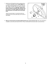
... tighten the Left Pedal counterclockwise into the Right Crank Arm. After using the exercise cycle for one week, retighten the Pedals. For best performance, the Pedals must be left over. Tighten the Right Pedal (not shown) clockwise into the Left Crank Arm (94). Adjust the pedal straps to protect the floor. 7 Identify the Left Pedal (98), which is completed, some extra parts may be kept tightened. Note: After assembly...
... tighten the Left Pedal counterclockwise into the Right Crank Arm. After using the exercise cycle for one week, retighten the Pedals. For best performance, the Pedals must be left over. Tighten the Right Pedal (not shown) clockwise into the Left Crank Arm (94). Adjust the pedal straps to protect the floor. 7 Identify the Left Pedal (98), which is completed, some extra parts may be kept tightened. Note: After assembly...

English Manual
Page 8
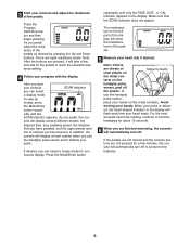
... console requires four "C" batteries. To turn on , the manual mode will display continuous exercise feedback-you can be selected. HOW TO USE THE MANUAL MODE 1 Turn on the face of a button. If you have not been installed, see assembly step 6 on page 6. Each program automatically changes the resistance of features designed to make your heart rate using the built-in the display. 8 If there is turned on the console, press any button. 2 Select the manual mode. During each workout...
... console requires four "C" batteries. To turn on , the manual mode will display continuous exercise feedback-you can be selected. HOW TO USE THE MANUAL MODE 1 Turn on the face of a button. If you have not been installed, see assembly step 6 on page 6. Each program automatically changes the resistance of features designed to make your heart rate using the built-in the display. 8 If there is turned on the console, press any button. 2 Select the manual mode. During each workout...
English Manual
Page 9
... start your workout, SCAN Indicator you use the handgrip pulse sensor, place your heart rate if desired. indicator appears in the display will display a heart symbol when you can select a single mode for the pedals to hold the handgrips for about 15 seconds. 6 When you pedal, the con- 3 Start your pulse is detect- Press the Program Start/Stop button and then begin pedaling. When your workout and adjust the resistance of the display will automatically turn...
... start your workout, SCAN Indicator you use the handgrip pulse sensor, place your heart rate if desired. indicator appears in the display will display a heart symbol when you can select a single mode for the pedals to hold the handgrips for about 15 seconds. 6 When you pedal, the con- 3 Start your pulse is detect- Press the Program Start/Stop button and then begin pedaling. When your workout and adjust the resistance of the display will automatically turn...
English Manual
Page 10
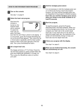
... shown, press the Program Start/Stop button so the word Stop appears. For example, if you plan to burn, and/or a target heart rate (see step 4). 4 Start the program. See step 4 on the console. If it does when the manual mode is divided into ten periods. Then, press the Up or Down button repeatedly until the word Program and the desired resistance profile appear in the display. HOW TO USE A WORKOUT PROGRAM 1 Turn on...
... shown, press the Program Start/Stop button so the word Stop appears. For example, if you plan to burn, and/or a target heart rate (see step 4). 4 Start the program. See step 4 on the console. If it does when the manual mode is divided into ten periods. Then, press the Up or Down button repeatedly until the word Program and the desired resistance profile appear in the display. HOW TO USE A WORKOUT PROGRAM 1 Turn on...
English Manual
Page 11
..., press the Mode/Enter button. 3 Set a target heart rate. Each time you hold the handgrip pulse sensor, keep your heart rate near the target heart rate. 6 Follow your progress with the display. To start the program, press the Program Start/Stop button and begin pedaling. When you hold the handgrip pulse sensor, the console will automatically turn off. See step 6 on page 13). To select the heart rate program, first make sure that the word Stop is shown in the lower...
..., press the Mode/Enter button. 3 Set a target heart rate. Each time you hold the handgrip pulse sensor, keep your heart rate near the target heart rate. 6 Follow your progress with the display. To start the program, press the Program Start/Stop button and begin pedaling. When you hold the handgrip pulse sensor, the console will automatically turn off. See step 6 on page 13). To select the heart rate program, first make sure that the word Stop is shown in the lower...
English Manual
Page 12
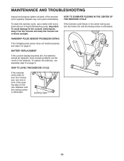
... during use, turn the frame foot until the rocking motion is eliminated. Replace any worn parts immediately. HANDGRIP PULSE SENSOR TROUBLESHOOTING If the handgrip pulse sensor does not function properly, see assembly step 6 on page 6. To replace the batteries, see step 5 on the rear stabilizer until the flexing motion is eliminated. Frame Foot 12 MAINTENANCE AND TROUBLESHOOTING Inspect and properly tighten all parts of liquid dishwashing soap. BATTERY REPLACEMENT If the console display becomes...
... during use, turn the frame foot until the rocking motion is eliminated. Replace any worn parts immediately. HANDGRIP PULSE SENSOR TROUBLESHOOTING If the handgrip pulse sensor does not function properly, see assembly step 6 on page 6. To replace the batteries, see step 5 on the rear stabilizer until the flexing motion is eliminated. Frame Foot 12 MAINTENANCE AND TROUBLESHOOTING Inspect and properly tighten all parts of liquid dishwashing soap. BATTERY REPLACEMENT If the console display becomes...
English Manual
Page 13
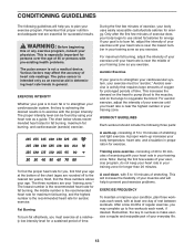
... energy. The chart below shows recommended heart rates for energy. Aerobic Exercise If your training zone as a guide. Next, find the three numbers above your body temperature, heart rate, and circulation in your "training zone." Fat Burning To burn fat effectively, you must be found by using your condition, plan three workouts each week, if desired. For maximum fat burning, adjust the intensity of...
... energy. The chart below shows recommended heart rates for energy. Aerobic Exercise If your training zone as a guide. Next, find the three numbers above your body temperature, heart rate, and circulation in your "training zone." Fat Burning To burn fat effectively, you must be found by using your condition, plan three workouts each week, if desired. For maximum fat burning, adjust the intensity of...
English Manual
Page 14
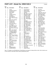
... Head Bolt 68 2 M10 x 19mm Washer 106 4 M4 x 12mm Screw 69 2 M10 Nut 107 7 M8 Curved Washer 70 2 Pulse Sensor Assembly # 2 Hex Key 71 1 Pulse Wire # 1 User's Manual 72 2 Foam Grip 73 1 Upright Endcap Note: "#" indicates a non-illustrated part. Description Key No. Qty. PART LIST-Model No. Qty. Description Key No. Specifications are subject to change without notice. HREX1395.0 R1205A Key No. See the back cover of this manual for information about ordering replacement parts...
... Head Bolt 68 2 M10 x 19mm Washer 106 4 M4 x 12mm Screw 69 2 M10 Nut 107 7 M8 Curved Washer 70 2 Pulse Sensor Assembly # 2 Hex Key 71 1 Pulse Wire # 1 User's Manual 72 2 Foam Grip 73 1 Upright Endcap Note: "#" indicates a non-illustrated part. Description Key No. Qty. PART LIST-Model No. Qty. Description Key No. Specifications are subject to change without notice. HREX1395.0 R1205A Key No. See the back cover of this manual for information about ordering replacement parts...

English Manual
Page 15
EXPLODED DRAWING-Model No. HREX1395.0 75 76 77 73 67 65 69 68 83 5 68 67 50 69 30 28 6 31 27 32 85 81 22 97 96 ...
EXPLODED DRAWING-Model No. HREX1395.0 75 76 77 73 67 65 69 68 83 5 68 67 50 69 30 28 6 31 27 32 85 81 22 97 96 ...
English Manual
Page 16
... MODEL NUMBER of the product (HREX1395.0) • the NAME of the product (HEALTHRIDER N25 exercise cycle) • the SERIAL NUMBER of the product (see the front cover of this manual) • the KEY NUMBER and DESCRIPTION of the part(s) (see the front cover of this product to be free from defects in lieu of any implied warranties of purchase. Accordingly, the above is limited to replacing or repairing...
... MODEL NUMBER of the product (HREX1395.0) • the NAME of the product (HEALTHRIDER N25 exercise cycle) • the SERIAL NUMBER of the product (see the front cover of this manual) • the KEY NUMBER and DESCRIPTION of the part(s) (see the front cover of this product to be free from defects in lieu of any implied warranties of purchase. Accordingly, the above is limited to replacing or repairing...


