User Manual
Page 3
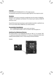
... information, carefully read the User's Manual. „„ For product-related information, check on our website at: https://www.gigabyte.com Identifying Your Motherboard Revision The revision number on your motherboard revision before updating motherboard BIOS, drivers, or when looking for technical information. The trademarks mentioned in this manual is protected by...
... information, carefully read the User's Manual. „„ For product-related information, check on our website at: https://www.gigabyte.com Identifying Your Motherboard Revision The revision number on your motherboard revision before updating motherboard BIOS, drivers, or when looking for technical information. The trademarks mentioned in this manual is protected by...
User Manual
Page 4
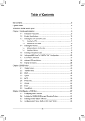
Table of Contents Box Contents...6 Optional Items...6 X299-WU8 Motherboard Layout 7 Chapter 1 Hardware Installation 9 1-1 Installation Precautions 9 1-2 Product Specifications 10 1-3 Installing the CPU and CPU Cooler 14 1-3-1 Installing the CPU......; SLI™ Configuration 20 1-7 Back Panel Connectors 22 1-8 Onboard LEDs and Buttons 24 1-9 Internal Connectors 25 Chapter 2 BIOS Setup 39 2-1 Startup Screen 40 2-2 The Main Menu 41 2-3 M.I.T...43 2-4 System...55 2-5 BIOS...56 2-6 Peripherals...59 2-7 Chipset...62 2-8 Power...63 2-9 Save & Exit...65 Chapter 3 Configuring a RAID Set 67 ...
Table of Contents Box Contents...6 Optional Items...6 X299-WU8 Motherboard Layout 7 Chapter 1 Hardware Installation 9 1-1 Installation Precautions 9 1-2 Product Specifications 10 1-3 Installing the CPU and CPU Cooler 14 1-3-1 Installing the CPU......; SLI™ Configuration 20 1-7 Back Panel Connectors 22 1-8 Onboard LEDs and Buttons 24 1-9 Internal Connectors 25 Chapter 2 BIOS Setup 39 2-1 Startup Screen 40 2-2 The Main Menu 41 2-3 M.I.T...43 2-4 System...55 2-5 BIOS...56 2-6 Peripherals...59 2-7 Chipset...62 2-8 Power...63 2-9 Save & Exit...65 Chapter 3 Configuring a RAID Set 67 ...

User Manual
Page 5
Chapter 4 Drivers Installation 89 4-1 Drivers & Software 89 4-2 Application Software 90 4-3 Information...90 Chapter 5 Unique Features 91 5-1 BIOS Update Utilities 91 5-1-1 Updating the BIOS with the Q-Flash Utility 91 5-1-2 Updating the BIOS with the @BIOS Utility 94 5-2 APP Center...95 5-2-1 3D OSD...96 5-2-2 AutoGreen...97 5-2-3 Cloud Station...98 5-2-4 EasyTune...103 5-2-5 Easy RAID...104 5-2-6 Fast Boot...106...
Chapter 4 Drivers Installation 89 4-1 Drivers & Software 89 4-2 Application Software 90 4-3 Information...90 Chapter 5 Unique Features 91 5-1 BIOS Update Utilities 91 5-1-1 Updating the BIOS with the Q-Flash Utility 91 5-1-2 Updating the BIOS with the @BIOS Utility 94 5-2 APP Center...95 5-2-1 3D OSD...96 5-2-2 AutoGreen...97 5-2-3 Cloud Station...98 5-2-4 EasyTune...103 5-2-5 Easy RAID...104 5-2-6 Fast Boot...106...
User Manual
Page 12
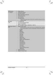
... Center * Available applications in APP Center may also vary depending on motherboard specifications. - 3D OSD - @BIOS - Smart Survey - Platform Power Management - Cloud Station - ON/OFF Charge - Easy RAID - Supported functions of licensed AMI UEFI...Install Hardware Installation - 12 - System Information Viewer - AutoGreen - Hardware Š Monitor Š Š Š Š Š Š BIOS Š Š Š Š Unique Features Š Š Š Voltage detection Temperature detection Fan speed detection Water cooling flow rate...
... Center * Available applications in APP Center may also vary depending on motherboard specifications. - 3D OSD - @BIOS - Smart Survey - Platform Power Management - Cloud Station - ON/OFF Charge - Easy RAID - Supported functions of licensed AMI UEFI...Install Hardware Installation - 12 - System Information Viewer - AutoGreen - Hardware Š Monitor Š Š Š Š Š Š BIOS Š Š Š Š Unique Features Š Š Š Voltage detection Temperature detection Fan speed detection Water cooling flow rate...
User Manual
Page 17
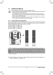
After the memory is recommended that the motherboard supports the memory. It is installed, the BIOS will automatically detect the specifications and capacity of the same capacity, brand, speed, and chips be installed in only one direction. If you ...are unable to insert the memory, switch the direction. 1-4-1 4 Channel Memory Configuration This motherboard supports 4 Channel Technology. A memory module can be used. (Go to GIGABYTE's website for memory installation according to the number of the memory modules you begin with the first socket of each channel has two memory sockets...
After the memory is recommended that the motherboard supports the memory. It is installed, the BIOS will automatically detect the specifications and capacity of the same capacity, brand, speed, and chips be installed in only one direction. If you ...are unable to insert the memory, switch the direction. 1-4-1 4 Channel Memory Configuration This motherboard supports 4 Channel Technology. A memory module can be used. (Go to GIGABYTE's website for memory installation according to the number of the memory modules you begin with the first socket of each channel has two memory sockets...
User Manual
Page 19
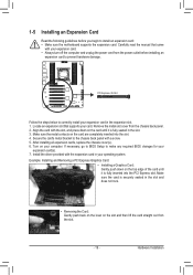
... to the chassis back panel with the expansion card in the slot. 3. Install the driver provided with a screw. 5. If necessary, go to BIOS Setup to make any required BIOS changes for your operating system. Locate an expansion slot that came with the slot, and press down on the top edge of the...
... to the chassis back panel with the expansion card in the slot. 3. Install the driver provided with a screw. 5. If necessary, go to BIOS Setup to make any required BIOS changes for your operating system. Locate an expansion slot that came with the slot, and press down on the top edge of the...
User Manual
Page 24
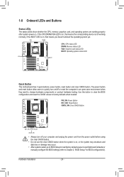
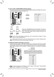
...loss or damage may occur. •• After system restart, go to BIOS Setup to load factory defaults (select Load Optimized Defaults) or manually configure the BIOS settings (refer to Chapter 2, "BIOS Setup," for BIOS configurations). Hardware Installation - 24 - if the BOOT LED is not working ...properly after system power-on , that means you haven't entered the operating system yet. Use this button to clear the BIOS configuration and reset the CMOS values to change hardware components or conduct hardware testing. 1-8 Onboard LEDs and Buttons Status LEDs The status...
...loss or damage may occur. •• After system restart, go to BIOS Setup to load factory defaults (select Load Optimized Defaults) or manually configure the BIOS settings (refer to Chapter 2, "BIOS Setup," for BIOS configurations). Hardware Installation - 24 - if the BOOT LED is not working ...properly after system power-on , that means you haven't entered the operating system yet. Use this button to clear the BIOS configuration and reset the CMOS values to change hardware components or conduct hardware testing. 1-8 Onboard LEDs and Buttons Status LEDs The status...
User Manual
Page 28
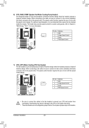
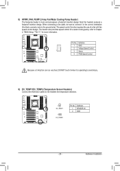
... control design. Definition 1 GND 1 2 Voltage Speed Control 3 Sense 4 PWM Speed Control •• Be sure to connect fan cables to the fan headers to Chapter 2, "BIOS Setup," "M.I.T.," for a water cooling pump, refer to prevent your CPU and system from overheating. Most fan headers possess a foolproof insertion design. Pin No. Most fan...
... control design. Definition 1 GND 1 2 Voltage Speed Control 3 Sense 4 PWM Speed Control •• Be sure to connect fan cables to the fan headers to Chapter 2, "BIOS Setup," "M.I.T.," for a water cooling pump, refer to prevent your CPU and system from overheating. Most fan headers possess a foolproof insertion design. Pin No. Most fan...
User Manual
Page 29
... Fan/Water Cooling Pump Header) The fan/pump header is operating to avoid injury. 9) EC_TEMP1/EC_TEMP2 (Temperature Sensor Headers) Connect the thermistor cables to Chapter 2, "BIOS Setup," "M.I.T.," for temperature detection. 1 EC_TEMP1 1 EC_TEMP2 Pin No. Definition 1 SENSOR IN 2 GND - 29 -
... Fan/Water Cooling Pump Header) The fan/pump header is operating to avoid injury. 9) EC_TEMP1/EC_TEMP2 (Temperature Sensor Headers) Connect the thermistor cables to Chapter 2, "BIOS Setup," "M.I.T.," for temperature detection. 1 EC_TEMP1 1 EC_TEMP2 Pin No. Definition 1 SENSOR IN 2 GND - 29 -
User Manual
Page 31
... a RAID array. 7531 SATA3 6 4 2 0 7 1 7 1 Pin No. 1 2 3 4 5 6 7 Definition GND TXP TXN GND RXN RXP GND To enable hot-plugging for the SATA ports, refer to Chapter 2, "BIOS Setup," "Peripherals\SATA And RST Configuration," for instructions on the plug) of the LED strip must be used to connect a standard 5050 RGB (RGBW) LED...
... a RAID array. 7531 SATA3 6 4 2 0 7 1 7 1 Pin No. 1 2 3 4 5 6 7 Definition GND TXP TXN GND RXN RXP GND To enable hot-plugging for the SATA ports, refer to Chapter 2, "BIOS Setup," "Peripherals\SATA And RST Configuration," for instructions on the plug) of the LED strip must be used to connect a standard 5050 RGB (RGBW) LED...

User Manual
Page 33
... of power switch, reset switch, power LED, hard drive activity LED, speaker and etc. When connecting your system using the power switch (refer to Chapter 2, "BIOS Setup," "Power," for more information). •• SPEAK (Speaker, Orange): Connects to the chassis intrusion switch/sensor on the chassis that can detect if the...
... of power switch, reset switch, power LED, hard drive activity LED, speaker and etc. When connecting your system using the power switch (refer to Chapter 2, "BIOS Setup," "Power," for more information). •• SPEAK (Speaker, Orange): Connects to the chassis intrusion switch/sensor on the chassis that can detect if the...

User Manual
Page 36
... one . Plug in the power cord and restart your computer. •• Always turn off . You may be used to keep the values (such as BIOS configurations, date, and time information) in accordance with an incorrect model. •• Contact the place of purchase or local dealer if you are not...
... one . Plug in the power cord and restart your computer. •• Always turn off . You may be used to keep the values (such as BIOS configurations, date, and time information) in accordance with an incorrect model. •• Contact the place of purchase or local dealer if you are not...
User Manual
Page 37
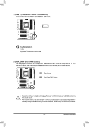
...a screwdriver to factory defaults. Hardware Installation B_ USB 0_ B 22) THB_C (Thunderbolt™ Add-in Card Connector) This connector is for a GIGABYTE Thunderbolt™ add-in card. 1 _ F_USB3 Supports a Thunderbolt™ add-in card. 23) CLR_CMOS (Clear CMOS Jumper) Use this jumper to clear... the BIOS configuration and reset the CMOS values to touch the two pins for BIOS configurations). - 37 - Open: Normal Short: Clear CMOS Values •• Always turn off your computer and ...
...a screwdriver to factory defaults. Hardware Installation B_ USB 0_ B 22) THB_C (Thunderbolt™ Add-in Card Connector) This connector is for a GIGABYTE Thunderbolt™ add-in card. 1 _ F_USB3 Supports a Thunderbolt™ add-in card. 23) CLR_CMOS (Clear CMOS Jumper) Use this jumper to clear... the BIOS configuration and reset the CMOS values to touch the two pins for BIOS configurations). - 37 - Open: Normal Short: Clear CMOS Values •• Always turn off your computer and ...
User Manual
Page 39
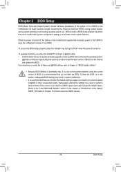
... and reset the board to default values. (Refer to activate certain system features. Inadequate BIOS flashing may result in this chapter or introductions of BIOS from the Internet and updates the BIOS. To upgrade the BIOS, use either the GIGABYTE Q-Flash or @BIOS utility. •• Q-Flash allows the user to boot. Its major functions include...
... and reset the board to default values. (Refer to activate certain system features. Inadequate BIOS flashing may result in this chapter or introductions of BIOS from the Internet and updates the BIOS. To upgrade the BIOS, use either the GIGABYTE Q-Flash or @BIOS utility. •• Q-Flash allows the user to boot. Its major functions include...

User Manual
Page 40
...boot device without having to accept. After system restart, the device boot order will still be based on BIOS Setup settings. : Q-FLASH Press the key to access the Q-Flash utility directly without entering BIOS Setup. In Boot Menu, use the up arrow key or the down arrow key to select the first... boot device, then press to enter BIOS Setup first. BIOS Setup - 40 - Function Keys Function Keys: : BIOS SETUP\Q-FLASH Press the key to enter BIOS Setup or to access the Q-Flash utility in Boot Menu is effective for one time only. The...
...boot device without having to accept. After system restart, the device boot order will still be based on BIOS Setup settings. : Q-FLASH Press the key to access the Q-Flash utility directly without entering BIOS Setup. In Boot Menu, use the up arrow key or the down arrow key to select the first... boot device, then press to enter BIOS Setup first. BIOS Setup - 40 - Function Keys Function Keys: : BIOS SETUP\Q-FLASH Press the key to enter BIOS Setup or to access the Q-Flash utility in Boot Menu is effective for one time only. The...
User Manual
Page 41
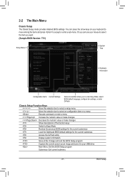
...the numeric value or make changes Show descriptions of the function keys Switch to Easy Mode Restore the previous BIOS settings for the current submenus Load the Optimized BIOS default settings for the current submenus Access the Q-Flash utility Display system information Save all the changes and ... your keyboard to move among the items and press to enter Easy Mode, select BIOS default language, configure fan settings, or enter Q-Flash. Or you to accept or enter a sub-menu. BIOS Setup Classic Setup Function Keys Move the selection bar to select a setup menu Move...
...the numeric value or make changes Show descriptions of the function keys Switch to Easy Mode Restore the previous BIOS settings for the current submenus Load the Optimized BIOS default settings for the current submenus Access the Q-Flash utility Display system information Save all the changes and ... your keyboard to move among the items and press to enter Easy Mode, select BIOS default language, configure fan settings, or enter Q-Flash. Or you to accept or enter a sub-menu. BIOS Setup Classic Setup Function Keys Move the selection bar to select a setup menu Move...

User Manual
Page 42
Easy Mode Easy Mode allows users to quickly view their current system information or to the Classic Setup screen. BIOS Setup - 42 - B. In Easy Mode, you can use your mouse to move through configuration items or press to switch to make adjustments for optimum performance.
Easy Mode Easy Mode allows users to quickly view their current system information or to the Classic Setup screen. BIOS Setup - 42 - B. In Easy Mode, you can use your mouse to move through configuration items or press to switch to make adjustments for optimum performance.

User Manual
Page 43
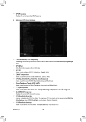
... other unexpected results. (Inadequately altering the settings may result in system's failure to CPU, chipset, or memory and reduce the useful life of these components. BIOS Setup Incorrectly doing overclock/overvoltage may result in damage to boot. The adjustable range is dependent on the CPU being installed. - 43 - This page is...
... other unexpected results. (Inadequately altering the settings may result in system's failure to CPU, chipset, or memory and reduce the useful life of these components. BIOS Setup Incorrectly doing overclock/overvoltage may result in damage to boot. The adjustable range is dependent on the CPU being installed. - 43 - This page is...
User Manual
Page 44
BIOS Setup - 44 - The maximum CPU clock ratio will be based on the CPU Flex Ratio Settings value if CPU Clock Ratio is dependent on the ...
BIOS Setup - 44 - The maximum CPU clock ratio will be based on the CPU Flex Ratio Settings value if CPU Clock Ratio is dependent on the ...
User Manual
Page 45
... the CPU specifications. (Default: Auto) && Core Current Limit (Amps) Allows you to determine whether to decrease power consumption. Auto lets the BIOS automatically configure this setting. (Default: Auto) - 45 - When enabled, the CPU core frequency and voltage will be reduced during system halt ...state to ramp up its operating frequency more enhanced power-saving state than C3. Auto lets the BIOS automatically configure this setting. (Default: Auto) && CPU Enhanced Halt (C1E) Enables or disables Intel® CPU Enhanced Halt (C1E) ...
... the CPU specifications. (Default: Auto) && Core Current Limit (Amps) Allows you to determine whether to decrease power consumption. Auto lets the BIOS automatically configure this setting. (Default: Auto) - 45 - When enabled, the CPU core frequency and voltage will be reduced during system halt ...state to ramp up its operating frequency more enhanced power-saving state than C3. Auto lets the BIOS automatically configure this setting. (Default: Auto) && CPU Enhanced Halt (C1E) Enables or disables Intel® CPU Enhanced Halt (C1E) ...


