User Manual
Page 3
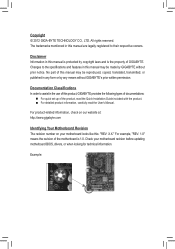
... looks like this product, GIGABYTE provides the following types of...In order to their respective owners. For example, "REV: 1.0" means the revision of GIGABYTE. The trademarks mentioned in this manual are legally registered to assist in this manual is 1.0....reproduced, copied, translated, transmitted, or published in this manual may be made by GIGABYTE without GIGABYTE's prior written permission. All rights reserved. Copyright © 2012 GIGA-BYTE TECHNOLOGY ... http://www.gigabyte.com Identifying Your Motherboard Revision The revision number on your motherboard revision before...
... looks like this product, GIGABYTE provides the following types of...In order to their respective owners. For example, "REV: 1.0" means the revision of GIGABYTE. The trademarks mentioned in this manual are legally registered to assist in this manual is 1.0....reproduced, copied, translated, transmitted, or published in this manual may be made by GIGABYTE without GIGABYTE's prior written permission. All rights reserved. Copyright © 2012 GIGA-BYTE TECHNOLOGY ... http://www.gigabyte.com Identifying Your Motherboard Revision The revision number on your motherboard revision before...

User Manual
Page 4
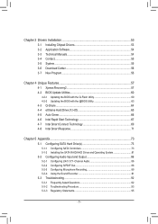
Table of Contents Box Contents...6 Optional Items...6 GA-Z77P-D3 Motherboard Layout 7 GA-Z77P-D3 Motherboard Block Diagram 8 Chapter 1 Hardware Installation 9 1-1 Installation Precautions 9 1-2 Product Specifications 10 1-3 Installing the CPU and CPU Cooler 13... 16 1-4-2 Installing a Memory 17 1-5 Installing an Expansion Card 18 1-6 Back Panel Connectors 19 1-7 Internal Connectors 21 Chapter 2 BIOS Setup 31 2-1 Startup Screen 32 2-2 The Main Menu 33 2-3 M.I.T...35 2-4 System...43 2-5 BIOS Features 44 2-6 Peripherals...46 2-7 Power Management 50 2-8 Save & Exit...52 - 4 -
Table of Contents Box Contents...6 Optional Items...6 GA-Z77P-D3 Motherboard Layout 7 GA-Z77P-D3 Motherboard Block Diagram 8 Chapter 1 Hardware Installation 9 1-1 Installation Precautions 9 1-2 Product Specifications 10 1-3 Installing the CPU and CPU Cooler 13... 16 1-4-2 Installing a Memory 17 1-5 Installing an Expansion Card 18 1-6 Back Panel Connectors 19 1-7 Internal Connectors 21 Chapter 2 BIOS Setup 31 2-1 Startup Screen 32 2-2 The Main Menu 33 2-3 M.I.T...35 2-4 System...43 2-5 BIOS Features 44 2-6 Peripherals...46 2-7 Power Management 50 2-8 Save & Exit...52 - 4 -
User Manual
Page 5
... 54 3-4 Contact...55 3-5 System...55 3-6 Download Center 56 3-7 New Program 56 Chapter 4 Unique Features 57 4-1 Xpress Recovery2 57 4-2 BIOS Update Utilities 60 4-2-1 Updating the BIOS with the Q-Flash Utility 60 4-2-2 Updating the BIOS with the @BIOS Utility 63 4-3 Q-Share...64 4-4 eXtreme Hard Drive (X.H.D 65 4-5 Auto Green...66 4-6 Intel Rapid Start Technology 67 4-7 Intel Smart...
... 54 3-4 Contact...55 3-5 System...55 3-6 Download Center 56 3-7 New Program 56 Chapter 4 Unique Features 57 4-1 Xpress Recovery2 57 4-2 BIOS Update Utilities 60 4-2-1 Updating the BIOS with the Q-Flash Utility 60 4-2-2 Updating the BIOS with the @BIOS Utility 63 4-3 Q-Share...64 4-4 eXtreme Hard Drive (X.H.D 65 4-5 Auto Green...66 4-6 Intel Rapid Start Technology 67 4-7 Intel Smart...
User Manual
Page 8
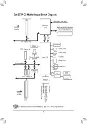
GA-Z77P-D3 Motherboard Block Diagram 1 PCI Express x16 CPU CLK+/- (100 MHz) PCIe CLK (100 MHz) LGA1155 CPU DDR3 1600/1333/1066 MHz Dual Channel Memory DMI 2.0 ... RJ45 Atheros/Realtek GbE LAN x4 x1 PCI Express Bus x1 x1 x1 PCIe to PCI Bridge 2 PCI Express x1 Intel® Z77 CODEC Dual BIOS 2 SATA 6Gb/s 3 SATA 3Gb/s 1 mSATA 4 USB 3.0/2.0 8 USB 2.0/1.1 LPC iTE Bus Super I/O COM PS/2 KB/Mouse MIC (Center/Subwoofer Speaker Out) Line Out (Front Speaker Out...
GA-Z77P-D3 Motherboard Block Diagram 1 PCI Express x16 CPU CLK+/- (100 MHz) PCIe CLK (100 MHz) LGA1155 CPU DDR3 1600/1333/1066 MHz Dual Channel Memory DMI 2.0 ... RJ45 Atheros/Realtek GbE LAN x4 x1 PCI Express Bus x1 x1 x1 PCIe to PCI Bridge 2 PCI Express x1 Intel® Z77 CODEC Dual BIOS 2 SATA 6Gb/s 3 SATA 3Gb/s 1 mSATA 4 USB 3.0/2.0 8 USB 2.0/1.1 LPC iTE Bus Super I/O COM PS/2 KB/Mouse MIC (Center/Subwoofer Speaker Out) Line Out (Front Speaker Out...
User Manual
Page 12
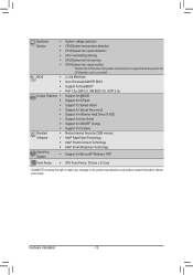
Hardware ŠŠ Monitor ŠŠ ŠŠ ŠŠ ŠŠ Š Š BIOS ŠŠ ŠŠ ŠŠ ŠŠ Unique Features ŠŠ ŠŠ ŠŠ ŠŠ ŠŠ ŠŠ ŠŠ... will depend on the CPU/system cooler you install. 2 x 64 Mbit flash Use of licensed AMI EFI BIOS Support for DualBIOS™ PnP 1.0a, DMI 2.0, SM BIOS 2.6, ACPI 2.0a Support for @BIOS Support for Q-Flash Support for Xpress Install Support for Xpress Recovery2 Support for eXtreme Hard Drive (X.H.D) Support for ...
Hardware ŠŠ Monitor ŠŠ ŠŠ ŠŠ ŠŠ Š Š BIOS ŠŠ ŠŠ ŠŠ ŠŠ Unique Features ŠŠ ŠŠ ŠŠ ŠŠ ŠŠ ŠŠ ŠŠ... will depend on the CPU/system cooler you install. 2 x 64 Mbit flash Use of licensed AMI EFI BIOS Support for DualBIOS™ PnP 1.0a, DMI 2.0, SM BIOS 2.6, ACPI 2.0a Support for @BIOS Support for Q-Flash Support for Xpress Install Support for Xpress Recovery2 Support for eXtreme Hard Drive (X.H.D) Support for ...
User Manual
Page 16
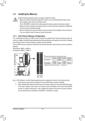
... that memory of the same capacity, brand, speed, and chips be used and installed in Dual Channel mode. 1. It is installed, the BIOS will double the original memory bandwidth. Hardware Installation - 16 - The four DDR3 memory sockets are unable to prevent hardware damage. ••...; Memory modules have a foolproof design. DS/SS - - Dual Channel mode cannot be used . (Go to GIGABYTE's website for the latest supported memory speeds and memory modules.) •• Always turn off the computer and unplug the power cord from the...
... that memory of the same capacity, brand, speed, and chips be used and installed in Dual Channel mode. 1. It is installed, the BIOS will double the original memory bandwidth. Hardware Installation - 16 - The four DDR3 memory sockets are unable to prevent hardware damage. ••...; Memory modules have a foolproof design. DS/SS - - Dual Channel mode cannot be used . (Go to GIGABYTE's website for the latest supported memory speeds and memory modules.) •• Always turn off the computer and unplug the power cord from the...
User Manual
Page 18
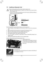
... off the computer and unplug the power cord from the power outlet before you begin to make any required BIOS changes for your expansion card in the slot. 3. If necessary, go to BIOS Setup to install an expansion card: •• Make sure the motherboard supports the expansion card. Remove the metal...
... off the computer and unplug the power cord from the power outlet before you begin to make any required BIOS changes for your expansion card in the slot. 3. If necessary, go to BIOS Setup to install an expansion card: •• Make sure the motherboard supports the expansion card. Remove the metal...
User Manual
Page 23
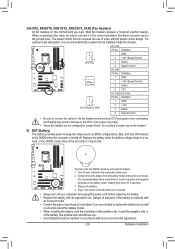
... 4-pin. 3/4) CPU_FAN/SYS_FAN1/SYS_FAN2/SYS_FAN3 (Fan Headers) All fan headers on the headers. 5) BAT (Battery) The battery provides power to keep the values (such as BIOS configurations, date, and time information) in the CMOS when the computer is turned off.
... 4-pin. 3/4) CPU_FAN/SYS_FAN1/SYS_FAN2/SYS_FAN3 (Fan Headers) All fan headers on the headers. 5) BAT (Battery) The battery provides power to keep the values (such as BIOS configurations, date, and time information) in the CMOS when the computer is turned off.
User Manual
Page 25
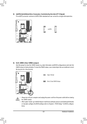
... a few seconds. Hardware Installation date information and BIOS configurat(ioGnA-sIV) Ba)nd reset the CMOS values to clear the CMOS values (e.g. DB_PORT BIOS Switcher (X58A-OC) 1 M_SATA Voltage measurement module(X58A-OC) PWM Switch (X58A-OC) mSATA ACPI_CPT (GA-IVB) DIP 1 23 1 DIP 1 23... 1 DIP 1 23 PCIe power connector (SATA)(X58A-OC) SMB_CPT (GA-IVB) G1.Sniper 3) CLR_CMOS CI DIS_ME GP15_CPT (GA-IVB) BIOS9S)...
... a few seconds. Hardware Installation date information and BIOS configurat(ioGnA-sIV) Ba)nd reset the CMOS values to clear the CMOS values (e.g. DB_PORT BIOS Switcher (X58A-OC) 1 M_SATA Voltage measurement module(X58A-OC) PWM Switch (X58A-OC) mSATA ACPI_CPT (GA-IVB) DIP 1 23 1 DIP 1 23... 1 DIP 1 23 PCIe power connector (SATA)(X58A-OC) SMB_CPT (GA-IVB) G1.Sniper 3) CLR_CMOS CI DIS_ME GP15_CPT (GA-IVB) BIOS9S)...
User Manual
Page 26
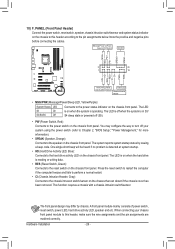
... panel. Message/Power/ Power Sleep LED Switch Speaker MSG+ MSG- RESRES+ CICI+ PWR+ PWR- When connecting your system using the power switch (refer to Chapter 2, "BIOS Setup," "Power Management," for more information). •• SPEAK (Speaker, Orange): Connects to the hard drive activity LED on the chassis front panel. Hardware Installation...
... panel. Message/Power/ Power Sleep LED Switch Speaker MSG+ MSG- RESRES+ CICI+ PWR+ PWR- When connecting your system using the power switch (refer to Chapter 2, "BIOS Setup," "Power Management," for more information). •• SPEAK (Speaker, Orange): Connects to the hard drive activity LED on the chassis front panel. Hardware Installation...
User Manual
Page 27
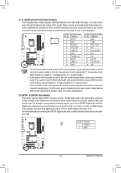
... 4 NC 5 LINE2_R 5 Line Out (R) 6 GND 6 NC 7 FAUDIO_JD 7 NC 8 No Pin 8 No Pin 9 LINE2_L 9 Line Out (L) DIP 1 23 1 DB_PORT 10 BIOS Switcher (X58A-OC) GND 10 NC •• The front panel audio header 1supports HD audio by expansion cards) for digital audio output from your...provided by default. Hardware Installation For example, some graphics cards may connect your motherboard to this header. GP15_CPT (GA-IVB) tage measurement points(G1.Sniper 3) BIOS Switcher (SW4) Pin No. Make sure the wire assignments of the module connector match the pin assignments of...
... 4 NC 5 LINE2_R 5 Line Out (R) 6 GND 6 NC 7 FAUDIO_JD 7 NC 8 No Pin 8 No Pin 9 LINE2_L 9 Line Out (L) DIP 1 23 1 DB_PORT 10 BIOS Switcher (X58A-OC) GND 10 NC •• The front panel audio header 1supports HD audio by expansion cards) for digital audio output from your...provided by default. Hardware Installation For example, some graphics cards may connect your motherboard to this header. GP15_CPT (GA-IVB) tage measurement points(G1.Sniper 3) BIOS Switcher (SW4) Pin No. Make sure the wire assignments of the module connector match the pin assignments of...
User Manual
Page 28
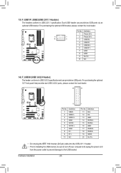
... two USB 3.0/2.0 ports, please contact the local dealer. 20 10 11 TPM w/housing Pin No. 1 2 3 4 5 6 7 8 9 10 Definition VBUS SSRX1SSRX1+ GND SSTX1SSTX1+ GND D1D1+ NC DB_PORT 1 BIOS Switc 1 1 Pin No. Voltage measurement points(G1.Sniper...
... two USB 3.0/2.0 ports, please contact the local dealer. 20 10 11 TPM w/housing Pin No. 1 2 3 4 5 6 7 8 9 10 Definition VBUS SSRX1SSRX1+ GND SSTX1SSTX1+ GND D1D1+ NC DB_PORT 1 BIOS Switc 1 1 Pin No. Voltage measurement points(G1.Sniper...
User Manual
Page 29
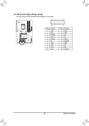
Definition 1 LCLK 2 GND 11 LAD0 12 GND PCIe power connector (SATA)(X58A-OC) 3 LFRAME 13 NC 4 No Pin 14 ID 5 LRESET 15 SB3V 6 NC 16 SERIRQ 7 LAD3 17 GND 8 LAD2 18 NC 9 VCC3 19 NC 10 LAD1 20 SUSCLK Voltage measurement points(G1.Sniper 3) BIOS Switcher (SW4) - 29 - Hardware Installation DB_PORT 15) TPM (Trusted Platform Module Header) You may connect a TPM (Trusted Platform Module) to this header. 19 TPM w/housing 20 1 Voltage measurement module(X58A-OC) 2 Pin No. Definition Pin No.
Definition 1 LCLK 2 GND 11 LAD0 12 GND PCIe power connector (SATA)(X58A-OC) 3 LFRAME 13 NC 4 No Pin 14 ID 5 LRESET 15 SB3V 6 NC 16 SERIRQ 7 LAD3 17 GND 8 LAD2 18 NC 9 VCC3 19 NC 10 LAD1 20 SUSCLK Voltage measurement points(G1.Sniper 3) BIOS Switcher (SW4) - 29 - Hardware Installation DB_PORT 15) TPM (Trusted Platform Module Header) You may connect a TPM (Trusted Platform Module) to this header. 19 TPM w/housing 20 1 Voltage measurement module(X58A-OC) 2 Pin No. Definition Pin No.
User Manual
Page 31
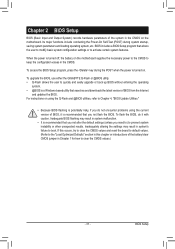
To upgrade the BIOS, use either the GIGABYTE Q-Flash or @BIOS utility. •• Q-Flash allows the user to quickly and easily upgrade or back up BIOS without entering the operating system. •• @BIOS is a Windows-based utility that searches and downloads the latest version of the battery...8226; It is recommended that you need to) to prevent system instability or other unexpected results. For instructions on . To access the BIOS Setup program, press the key during system startup, saving system parameters and loading operating system, etc. When the power is turned on...
To upgrade the BIOS, use either the GIGABYTE Q-Flash or @BIOS utility. •• Q-Flash allows the user to quickly and easily upgrade or back up BIOS without entering the operating system. •• @BIOS is a Windows-based utility that searches and downloads the latest version of the battery...8226; It is recommended that you need to) to prevent system instability or other unexpected results. For instructions on . To access the BIOS Setup program, press the key during system startup, saving system parameters and loading operating system, etc. When the power is turned on...
User Manual
Page 32
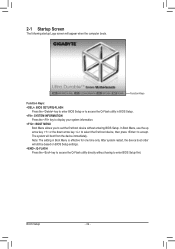
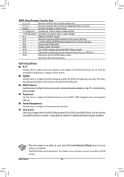
..., the device boot order will still be based on BIOS Setup settings. : Q-FLASH Press the key to access the Q-Flash utility directly without entering BIOS Setup. Function Keys Function Keys: : BIOS SETUP\Q-FLASH Press the key to enter BIOS Setup or to access the Q-Flash utility in Boot Menu... is effective for one time only. BIOS Setup - 32 - 2-1 Startup Screen The following startup...
..., the device boot order will still be based on BIOS Setup settings. : Q-FLASH Press the key to access the Q-Flash utility directly without entering BIOS Setup. Function Keys Function Keys: : BIOS SETUP\Q-FLASH Press the key to enter BIOS Setup or to access the Q-Flash utility in Boot Menu... is effective for one time only. BIOS Setup - 32 - 2-1 Startup Screen The following startup...
User Manual
Page 33
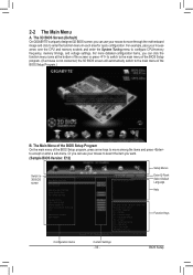
... CPU/memory frequency, memory timings, and voltage settings. The 3D BIOS Screen (Default) On GIGABYTE's uniquely designed 3D BIOS screen, you can use your mouse to select the item you can use your mouse to move among the items and press to 3D BIOS screen Setup Menus Enter Q-Flash Select Default Language Help Function...
... CPU/memory frequency, memory timings, and voltage settings. The 3D BIOS Screen (Default) On GIGABYTE's uniquely designed 3D BIOS screen, you can use your mouse to select the item you can use your mouse to move among the items and press to 3D BIOS screen Setup Menus Enter Q-Flash Select Default Language Help Function...
User Manual
Page 34
... voltages of your CPU and memory, etc. This menu also displays information on the devices connected to the SATA ports. „„ BIOS Features Use this menu to configure the device boot order, advanced features available on a menu Execute command or enter a menu / Increase...the numeric value or make changes / Decrease the numeric value or make changes Switch to 3D BIOS screen Restore the previous BIOS settings for the current submenus Load the Optimized BIOS default settings for the current submenus Access the Q-Flash utility Display system information Save all the ...
... voltages of your CPU and memory, etc. This menu also displays information on the devices connected to the SATA ports. „„ BIOS Features Use this menu to configure the device boot order, advanced features available on a menu Execute command or enter a menu / Increase...the numeric value or make changes / Decrease the numeric value or make changes Switch to 3D BIOS screen Restore the previous BIOS settings for the current submenus Load the Optimized BIOS default settings for the current submenus Access the Q-Flash utility Display system information Save all the ...
User Manual
Page 35
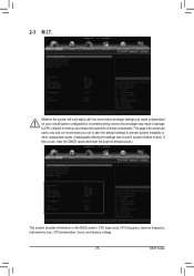
... values.) This section provides information on your overall system configurations. This page is dependent on the BIOS version, CPU base clock, CPU frequency, memory frequency, total memory size , CPU temperature, Vcore, and memory voltage. - 35 - BIOS Setup 2-3 M.I.T. Incorrectly doing overclock/overvoltage may result in damage to CPU, chipset, or memory and reduce...
... values.) This section provides information on your overall system configurations. This page is dependent on the BIOS version, CPU base clock, CPU frequency, memory frequency, total memory size , CPU temperature, Vcore, and memory voltage. - 35 - BIOS Setup 2-3 M.I.T. Incorrectly doing overclock/overvoltage may result in damage to CPU, chipset, or memory and reduce...
User Manual
Page 36
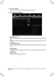
...) Important: It is from 400 MHz to 1600 MHz. (Default: Auto) && CPU Clock Ratio Allows you to alter the clock ratio for the installed CPU. BIOS Setup - 36 - Current Status This screen provides information on the CPU being installed. && CPU Frequency Displays the current operating CPU frequency. `` M.I.T.
...) Important: It is from 400 MHz to 1600 MHz. (Default: Auto) && CPU Clock Ratio Allows you to alter the clock ratio for the installed CPU. BIOS Setup - 36 - Current Status This screen provides information on the CPU being installed. && CPU Frequency Displays the current operating CPU frequency. `` M.I.T.
User Manual
Page 37
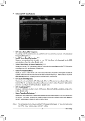
...limit, the CPU will automatically reduce the core frequency in order to reduce the power. BIOS Setup This feature only works for operating systems that supports this function. Auto lets the BIOS automatically configure this setting. (Default: Auto) && Hyper-Threading Technology (Note) Allows you... exceeds the specified current limit, the CPU will automatically reduce the core frequency in order to reduce the current. Auto lets the BIOS automatically configure this setting. (Default: Auto) (Note) This item is present only when you install a CPU that support multi-processor...
...limit, the CPU will automatically reduce the core frequency in order to reduce the power. BIOS Setup This feature only works for operating systems that supports this function. Auto lets the BIOS automatically configure this setting. (Default: Auto) && Hyper-Threading Technology (Note) Allows you... exceeds the specified current limit, the CPU will automatically reduce the core frequency in order to reduce the current. Auto lets the BIOS automatically configure this setting. (Default: Auto) (Note) This item is present only when you install a CPU that support multi-processor...


