User Manual
Page 3
..., carefully read the User's Manual. For example, "REV: 1.0" means the revision of GIGABYTE. For product-related information, check on our website at: http://www.gigabyte.com Identifying Your Motherboard Revision The revision number on your motherboard revision before updating motherboard BIOS, drivers, or when looking for technical information. Changes to the specifications and...
..., carefully read the User's Manual. For example, "REV: 1.0" means the revision of GIGABYTE. For product-related information, check on our website at: http://www.gigabyte.com Identifying Your Motherboard Revision The revision number on your motherboard revision before updating motherboard BIOS, drivers, or when looking for technical information. Changes to the specifications and...
User Manual
Page 4
Table of Contents Box Contents...6 Optional Items...6 GA-X79-UD5 Motherboard Layout 7 GA-X79-UD5 Motherboard Block Diagram 8 Chapter 1 Hardware Installation 9 1-1 Installation Precautions 9 1-2 Product Specifications 10 1-3 Installing the CPU and CPU Cooler 13 ...Card 18 1-6 Setting up AMD CrossFireX™/NVIDIA SLI Configuration 19 1-7 Back Panel Connectors 20 1-8 Internal Connectors 22 Chapter 2 BIOS Setup 33 2-1 Startup Screen 34 2-2 The Main Menu 35 2-3 M.I.T...37 2-4 System...50 2-5 BIOS Features 51 2-6 Peripherals...53 2-7 Power Management 56 2-8 Save & Exit Setup 58 - 4 -
Table of Contents Box Contents...6 Optional Items...6 GA-X79-UD5 Motherboard Layout 7 GA-X79-UD5 Motherboard Block Diagram 8 Chapter 1 Hardware Installation 9 1-1 Installation Precautions 9 1-2 Product Specifications 10 1-3 Installing the CPU and CPU Cooler 13 ...Card 18 1-6 Setting up AMD CrossFireX™/NVIDIA SLI Configuration 19 1-7 Back Panel Connectors 20 1-8 Internal Connectors 22 Chapter 2 BIOS Setup 33 2-1 Startup Screen 34 2-2 The Main Menu 35 2-3 M.I.T...37 2-4 System...50 2-5 BIOS Features 51 2-6 Peripherals...53 2-7 Power Management 56 2-8 Save & Exit Setup 58 - 4 -

User Manual
Page 5
...62 3-7 New Utilities...62 Chapter 4 Unique Features 63 4-1 Xpress Recovery2 63 4-2 BIOS Update Utilities 66 4-2-1 Updating the BIOS with the Q-Flash Utility 66 4-2-2 Updating the BIOS with the @BIOS Utility 69 4-3 EasyTune 6...70 4-4 Q-Share...71 4-5 Smart 6™ ...72 ...4-6 eXtreme Hard Drive (X.H.D 76 4-7 Cloud OC...77 4-8 TouchBIOS...78 Chapter 5 Appendix...79 5-1 Configuring SATA Hard Drive(s 79 5-1-1 Configuring Intel X79...
...62 3-7 New Utilities...62 Chapter 4 Unique Features 63 4-1 Xpress Recovery2 63 4-2 BIOS Update Utilities 66 4-2-1 Updating the BIOS with the Q-Flash Utility 66 4-2-2 Updating the BIOS with the @BIOS Utility 69 4-3 EasyTune 6...70 4-4 Q-Share...71 4-5 Smart 6™ ...72 ...4-6 eXtreme Hard Drive (X.H.D 76 4-7 Cloud OC...77 4-8 TouchBIOS...78 Chapter 5 Appendix...79 5-1 Configuring SATA Hard Drive(s 79 5-1-1 Configuring Intel X79...
User Manual
Page 8
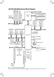
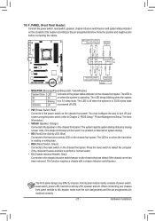
GA-X79-UD5 Motherboard Block Diagram 2 PCI Express x16 CPU CLK+/- (100 MHz) PCIe CLK (100 MHz) LGA2011 CPU DDR3 2133/1866/1600/1333/1066 MHz 4 Channel Memory 1 ... x1 x1 Intel GbE LAN phy 2 PCI Express x1 RJ45 PCI Bus LAN VIA VT6308 2 IEEE 1394a Intel® X79 CODEC 2 USB 3.0/2.0 2 USB 3.0/2.0 Fresco FL1009 Fresco FL1009 x1 x1 PCI Express Bus Dual BIOS 2 SATA 6Gb/s 4 SATA 3Gb/s 14 USB 2.0/1.1(Note) LPC Bus iTE IT8728 PS/2 KB/Mouse Surround Speaker Out Center...
GA-X79-UD5 Motherboard Block Diagram 2 PCI Express x16 CPU CLK+/- (100 MHz) PCIe CLK (100 MHz) LGA2011 CPU DDR3 2133/1866/1600/1333/1066 MHz 4 Channel Memory 1 ... x1 x1 Intel GbE LAN phy 2 PCI Express x1 RJ45 PCI Bus LAN VIA VT6308 2 IEEE 1394a Intel® X79 CODEC 2 USB 3.0/2.0 2 USB 3.0/2.0 Fresco FL1009 Fresco FL1009 x1 x1 PCI Express Bus Dual BIOS 2 SATA 6Gb/s 4 SATA 3Gb/s 14 USB 2.0/1.1(Note) LPC Bus iTE IT8728 PS/2 KB/Mouse Surround Speaker Out Center...

User Manual
Page 11
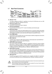
... 1 x S/PDIF Out header 3 x USB 2.0/1.1 headers 1 x USB 3.0/2.0 header 1 x IEEE 1394a header 1 x Clear CMOS jumper 1 x Trusted Platform Module (TPM) header 1 x PS/2 keyboard/mouse port 1 x CPU overclocking button 1 x BIOS switch button 1 x Clear CMOS button 1 x IEEE 1394 port 7 x USB 2.0/1.1 ports 2 x USB 3.0/2.0 ports 1 x eSATA/USB Combo connector 1 x eSATA 6Gb/s connector 1 x RJ-45 port 1 x optical S/PDIF Out...
... 1 x S/PDIF Out header 3 x USB 2.0/1.1 headers 1 x USB 3.0/2.0 header 1 x IEEE 1394a header 1 x Clear CMOS jumper 1 x Trusted Platform Module (TPM) header 1 x PS/2 keyboard/mouse port 1 x CPU overclocking button 1 x BIOS switch button 1 x Clear CMOS button 1 x IEEE 1394 port 7 x USB 2.0/1.1 ports 2 x USB 3.0/2.0 ports 1 x eSATA/USB Combo connector 1 x eSATA 6Gb/s connector 1 x RJ-45 port 1 x optical S/PDIF Out...
User Manual
Page 12
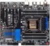
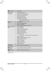
...flash ŠŠ Use of licensed AMI EFI BIOS ŠŠ Support for DualBIOS™ ŠŠ PnP 1.0a, DMI 2.0, SM BIOS 2.6, ACPI 2.0a Unique Features ŠŠ Support for @BIOS ŠŠ Support for Q-Flash ŠŠ Support for Xpress BIOS Rescue ŠŠ Support for Download Center &#...;Š Support for Microsoft® Windows 7/Vista/XP Form Factor ŠŠ E-ATX Form Factor; 30.5cm x 26.4cm * GIGABYTE reserves the right to make any changes to the product specifications and product-related information without prior notice. Hardware Installation - 12 -
...flash ŠŠ Use of licensed AMI EFI BIOS ŠŠ Support for DualBIOS™ ŠŠ PnP 1.0a, DMI 2.0, SM BIOS 2.6, ACPI 2.0a Unique Features ŠŠ Support for @BIOS ŠŠ Support for Q-Flash ŠŠ Support for Xpress BIOS Rescue ŠŠ Support for Download Center &#...;Š Support for Microsoft® Windows 7/Vista/XP Form Factor ŠŠ E-ATX Form Factor; 30.5cm x 26.4cm * GIGABYTE reserves the right to make any changes to the product specifications and product-related information without prior notice. Hardware Installation - 12 -
User Manual
Page 16
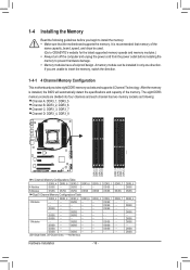
It is installed, the BIOS will automatically detect the specifications and capacity of the same capacity, brand, speed, and chips be installed in only one direction. DS/SS - - DS/SS - .../SS DS/SS DDR3_1 DS/SS DS/SS DS/SS - - - DS/SS DS/SS DS/SS - - DS/SS - A memory module can be used. (Go to GIGABYTE's website for the latest supported memory speeds and memory modules.) •• Always turn off the computer and unplug the power cord from the power...
It is installed, the BIOS will automatically detect the specifications and capacity of the same capacity, brand, speed, and chips be installed in only one direction. DS/SS - - DS/SS - .../SS DS/SS DDR3_1 DS/SS DS/SS DS/SS - - - DS/SS DS/SS DS/SS - - DS/SS - A memory module can be used. (Go to GIGABYTE's website for the latest supported memory speeds and memory modules.) •• Always turn off the computer and unplug the power cord from the power...

User Manual
Page 18
If necessary, go to BIOS Setup to make any required BIOS changes for your card. Locate an expansion slot that came with the expansion card in the slot. 3. Make sure the card is fully seated in ...
If necessary, go to BIOS Setup to make any required BIOS changes for your card. Locate an expansion slot that came with the expansion card in the slot. 3. Make sure the card is fully seated in ...
User Manual
Page 20
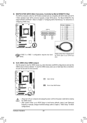
... a USB keyboard/mouse, USB printer, USB flash drive and etc. The green LED indicates the main BIOS is active and the blue LED indicates the backup BIOS is compatible to prevent an electrical short inside the cable connector. Or use this button to overclock your ... defaults when needed. eSATA 6Gb/s Connector This connector supports SATA 6Gb/s specification. Use the port to switch between the main BIOS and backup BIOS. The Marvell 88SE9172 chip supports RAID function. CPU Overclcking Button Press this port for instructions on configuring a RAID array. Refer to...
... a USB keyboard/mouse, USB printer, USB flash drive and etc. The green LED indicates the main BIOS is active and the blue LED indicates the backup BIOS is compatible to prevent an electrical short inside the cable connector. Or use this button to overclock your ... defaults when needed. eSATA 6Gb/s Connector This connector supports SATA 6Gb/s specification. Use the port to switch between the main BIOS and backup BIOS. The Marvell 88SE9172 chip supports RAID function. CPU Overclcking Button Press this port for instructions on configuring a RAID array. Refer to...

User Manual
Page 24
... optimum heat dissipation, it in accordance with fan speed control design. Definition Pin No. Overheating may result in damage to keep the values (such as BIOS configurations, date, and time information) in the power cord and restart your computer. •• Always turn off . Do not place a jumper cap on the...
... optimum heat dissipation, it in accordance with fan speed control design. Definition Pin No. Overheating may result in damage to keep the values (such as BIOS configurations, date, and time information) in the power cord and restart your computer. •• Always turn off . Do not place a jumper cap on the...
User Manual
Page 26
... CMOS Values •• Always turn off your SATA hard drive. 9) CLR_CMOS (Clear CMOS Jumper) Use this jumper to Chapter 2, "BIOS Setup," for instructions on configuring a RAID array. Refer to touch the two pins for a few seconds. 8) GSATA3 6/7/8/9 (SATA 6Gb/s... TXP 3 TXN 4 GND 5 RXN 6 RXP 7 GND DEBUG PORT A RAID 0 or RAID 1 configuration requires two hard drives. Hardware Installation - 26 - date information and BIOS configurations) and reset the CMOS values to SATA 6Gb/s standard and are compatible with SATA 3Gb/s and SATA 1.5Gb/s standard. Each SATA connector supports a single...
... CMOS Values •• Always turn off your SATA hard drive. 9) CLR_CMOS (Clear CMOS Jumper) Use this jumper to Chapter 2, "BIOS Setup," for instructions on configuring a RAID array. Refer to touch the two pins for a few seconds. 8) GSATA3 6/7/8/9 (SATA 6Gb/s... TXP 3 TXN 4 GND 5 RXN 6 RXP 7 GND DEBUG PORT A RAID 0 or RAID 1 configuration requires two hard drives. Hardware Installation - 26 - date information and BIOS configurations) and reset the CMOS values to SATA 6Gb/s standard and are compatible with SATA 3Gb/s and SATA 1.5Gb/s standard. Each SATA connector supports a single...
User Manual
Page 27
... S1 S3/S4/S5 Blinking is operating. You may differ by issuing a beep code. When connecting your system using the power switch (refer to Chapter 2, "BIOS Setup," "Power Management Setup," for more information). •• SPEAK (Speaker, Orange): Connects to the speaker on the chassis front panel. Note the positive and...
... S1 S3/S4/S5 Blinking is operating. You may differ by issuing a beep code. When connecting your system using the power switch (refer to Chapter 2, "BIOS Setup," "Power Management Setup," for more information). •• SPEAK (Speaker, Orange): Connects to the speaker on the chassis front panel. Note the positive and...

User Manual
Page 28
... 5 LINE2_R 4 NC 5 Line Out (R) 6 GND 6 NC 7 FAUDIO_JD 7 NC 8 No Pin 8 No Pin 9 LINE2_L 9 Line Out (L) 10 GND 10 NC DIP 1 23 1 DIP 1 23 1 DIP 1 23 1 BIOS Switcher (X58A-OC) DB_P•O•RTThe front panel audio header supports HD audio by expansion cardPsC)Iefoprowdeigr citoanlnaecutodrio(SAoTuAt)p(Xu5t8Afr-oOmC) your motherboard to...
... 5 LINE2_R 4 NC 5 Line Out (R) 6 GND 6 NC 7 FAUDIO_JD 7 NC 8 No Pin 8 No Pin 9 LINE2_L 9 Line Out (L) 10 GND 10 NC DIP 1 23 1 DIP 1 23 1 DIP 1 23 1 BIOS Switcher (X58A-OC) DB_P•O•RTThe front panel audio header supports HD audio by expansion cardPsC)Iefoprowdeigr citoanlnaecutodrio(SAoTuAt)p(Xu5t8Afr-oOmC) your motherboard to...

User Manual
Page 29
... 1 Power (5V) 2 Power (5V) 9 1 10 2 3 USB DX- 4 USB DY- 5 USB DX+ 6 USB DY+ 7 GND 8 GND DIP 9 No Pin 1 23 10 NC 1 PWM Switch (X58A-OC) BIOS Switcher (X58A-OC) 1 M_SATA DIP 1 23 PCIe power connector (SATA)(X58A-OC) DIP 1 23 1 DIP 1 23 1 Voltage measurement module(X58A-OC) DB_PORT F_AUDIO(H) 14) F_USB30...
... 1 Power (5V) 2 Power (5V) 9 1 10 2 3 USB DX- 4 USB DY- 5 USB DX+ 6 USB DY+ 7 GND 8 GND DIP 9 No Pin 1 23 10 NC 1 PWM Switch (X58A-OC) BIOS Switcher (X58A-OC) 1 M_SATA DIP 1 23 PCIe power connector (SATA)(X58A-OC) DIP 1 23 1 DIP 1 23 1 Voltage measurement module(X58A-OC) DB_PORT F_AUDIO(H) 14) F_USB30...

User Manual
Page 30
... PCIe power connector (SATA)(X58A-OC) 13 NC 14 RSV 15 SB3V 16 SERIRQ 17 GND 18 NC 19 NC 20 SUSCLK 1 Hardware Installation - 30 - BIOS Switc 1 1 19 TPM w/housing 20 Pin No. Definition 1 LCLK 2 GND 3 LFRAME 4 No Pin 5 LRESET 6 NC 7 LAD3 8 LAD2 9 VCC3 10 LAD1 1 Voltage measurement module(X58A-OC...
... PCIe power connector (SATA)(X58A-OC) 13 NC 14 RSV 15 SB3V 16 SERIRQ 17 GND 18 NC 19 NC 20 SUSCLK 1 Hardware Installation - 30 - BIOS Switc 1 1 19 TPM w/housing 20 Pin No. Definition 1 LCLK 2 GND 3 LFRAME 4 No Pin 5 LRESET 6 NC 7 LAD3 8 LAD2 9 VCC3 10 LAD1 1 Voltage measurement module(X58A-OC...
User Manual
Page 33
... the battery/clearing CMOS jumper/button in system malfunction. •• BIOS will emit a beep code during system startup, saving system parameters and loading operating system, etc. Chapter 2 BIOS Setup BIOS (Basic Input and Output System) records hardware parameters of the system in...include conducting the Power-On Self-Test (POST) during the POST. Inadequate BIOS flashing may result in system's failure to activate certain system features. BIOS Setup To upgrade the BIOS, use either the GIGABYTE Q-Flash or @BIOS utility. •• Q-Flash allows the user to clear the CMOS...
... the battery/clearing CMOS jumper/button in system malfunction. •• BIOS will emit a beep code during system startup, saving system parameters and loading operating system, etc. Chapter 2 BIOS Setup BIOS (Basic Input and Output System) records hardware parameters of the system in...include conducting the Power-On Self-Test (POST) during the POST. Inadequate BIOS flashing may result in system's failure to activate certain system features. BIOS Setup To upgrade the BIOS, use either the GIGABYTE Q-Flash or @BIOS utility. •• Q-Flash allows the user to clear the CMOS...

User Manual
Page 34
... settings. : Q-FLASH Press the key to access the Q-Flash utility directly without having to set the first boot device without entering BIOS Setup. In Boot Menu, use the up arrow key or the down arrow key to select the first boot device, then press to skip the ...startup Logo. 2-1 Startup Screen The following startup Logo screen will boot from the device immediately. Note: The setting in BIOS Setup. : SYSTEM INFORMATION Press the key to display your system information. : BOOT MENU Boot Menu allows you to enter...
... settings. : Q-FLASH Press the key to access the Q-Flash utility directly without having to set the first boot device without entering BIOS Setup. In Boot Menu, use the up arrow key or the down arrow key to select the first boot device, then press to skip the ...startup Logo. 2-1 Startup Screen The following startup Logo screen will boot from the device immediately. Note: The setting in BIOS Setup. : SYSTEM INFORMATION Press the key to display your system information. : BOOT MENU Boot Menu allows you to enter...
User Manual
Page 35
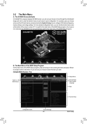
... Program On the main menu of the BIOS Setup Program.) B. BIOS Setup The 3D BIOS Screen (Default) On GIGABYTE's uniquely designed 3D BIOS screen, you can click the function menu icons at the bottom of the screen or press to switch to the main menu of the BIOS Setup program. (If a mouse is ...not connected, the 3D BIOS screen will automatically ...
... Program On the main menu of the BIOS Setup Program.) B. BIOS Setup The 3D BIOS Screen (Default) On GIGABYTE's uniquely designed 3D BIOS screen, you can click the function menu icons at the bottom of the screen or press to switch to the main menu of the BIOS Setup program. (If a mouse is ...not connected, the 3D BIOS screen will automatically ...

User Manual
Page 36
...Increase the numeric value or make changes / Decrease the numeric value or make changes Switch to 3D BIOS screen Restore the previous BIOS settings for the current menu Load the optimized BIOS default settings for the current menu Access the Q-Flash utility Display system information Save all the changes made...not stable as an image and save it to your system to its defaults. •• The BIOS Setup menus described in the BIOS Setup program to the CMOS and exit BIOS Setup. Or check the system/CPU temperatures, voltages, and fan speeds. „„ System Use this...
...Increase the numeric value or make changes / Decrease the numeric value or make changes Switch to 3D BIOS screen Restore the previous BIOS settings for the current menu Load the optimized BIOS default settings for the current menu Access the Q-Flash utility Display system information Save all the changes made...not stable as an image and save it to your system to its defaults. •• The BIOS Setup menus described in the BIOS Setup program to the CMOS and exit BIOS Setup. Or check the system/CPU temperatures, voltages, and fan speeds. „„ System Use this...

User Manual
Page 37
... page is dependent on the BIOS version, CPU base clock, CPU frequency, memory frequency, total memory size , CPU temperature, Vcore, and memory voltages. - 37 - Whether the system will work stably with ...
... page is dependent on the BIOS version, CPU base clock, CPU frequency, memory frequency, total memory size , CPU temperature, Vcore, and memory voltages. - 37 - Whether the system will work stably with ...


