
Manual
Page 1
...RAID 0 array. 2. The following procedure details the steps to the biggest drive in the Intel Chipset. (Note 2) It is added. B. Using GIGABYTE eXtreme Hard Drive (X.H.D) Instructions:(Note 2) Before launching X.H.D, make sure the newly added harddrive has equal or greater capacity than or equal to set up ...a RAID 0 array later using the Auto function. Setting Up a RAID-Ready System Step 1: Configure the system BIOS Enter the system BIOS Setup program, set up a RAID array: (Note 3): Click Manual to access the Intel Matrix Storage Console, with a simple click of ...
...RAID 0 array. 2. The following procedure details the steps to the biggest drive in the Intel Chipset. (Note 2) It is added. B. Using GIGABYTE eXtreme Hard Drive (X.H.D) Instructions:(Note 2) Before launching X.H.D, make sure the newly added harddrive has equal or greater capacity than or equal to set up ...a RAID 0 array later using the Auto function. Setting Up a RAID-Ready System Step 1: Configure the system BIOS Enter the system BIOS Setup program, set up a RAID array: (Note 3): Click Manual to access the Intel Matrix Storage Console, with a simple click of ...
Manual
Page 3
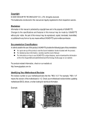
... read or download the information on/from the Support&Downloads\Motherboard\Technology Guide page on your motherboard revision before updating motherboard BIOS, drivers, or when looking for technical information. The trademarks mentioned in any means without prior notice. For product-related ... to use of this manual may be reproduced, copied, translated, transmitted, or published in this manual may be made by GIGABYTE without GIGABYTE's prior written permission. Check your motherboard looks like this manual is protected by any form or by copyright laws and is...
... read or download the information on/from the Support&Downloads\Motherboard\Technology Guide page on your motherboard revision before updating motherboard BIOS, drivers, or when looking for technical information. The trademarks mentioned in any means without prior notice. For product-related ... to use of this manual may be reproduced, copied, translated, transmitted, or published in this manual may be made by GIGABYTE without GIGABYTE's prior written permission. Check your motherboard looks like this manual is protected by any form or by copyright laws and is...
Manual
Page 4
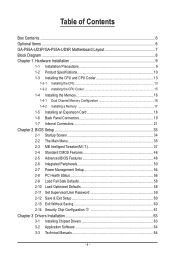
Table of Contents Box Contents...6 Optional Items...6 GA-P55A-UD3P/GA-P55A-UD3R Motherboard Layout 7 Block Diagram...8 Chapter 1 Hardware Installation 9 1-1 Installation Precautions 9 1-2 Product Specifications 10 1-3 Installing the CPU and CPU ... Installing an Expansion Card 18 1-6 Back Panel Connectors 19 1-7 Internal Connectors 21 Chapter 2 BIOS Setup 33 2-1 Startup Screen 34 2-2 The Main Menu 35 2-3 MB Intelligent Tweaker(M.I.T 37 2-4 Standard CMOS Features 46 2-5 Advanced BIOS Features 48 2-6 Integrated Peripherals 50 2-7 Power Management Setup 54 2-8 PC Health Status 56...
Table of Contents Box Contents...6 Optional Items...6 GA-P55A-UD3P/GA-P55A-UD3R Motherboard Layout 7 Block Diagram...8 Chapter 1 Hardware Installation 9 1-1 Installation Precautions 9 1-2 Product Specifications 10 1-3 Installing the CPU and CPU ... Installing an Expansion Card 18 1-6 Back Panel Connectors 19 1-7 Internal Connectors 21 Chapter 2 BIOS Setup 33 2-1 Startup Screen 34 2-2 The Main Menu 35 2-3 MB Intelligent Tweaker(M.I.T 37 2-4 Standard CMOS Features 46 2-5 Advanced BIOS Features 48 2-6 Integrated Peripherals 50 2-7 Power Management Setup 54 2-8 PC Health Status 56...
Manual
Page 5
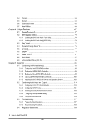
3-4 Contact...65 3-5 System...65 3-6 Download Center 66 3-7 New Utilities...66 Chapter 4 Unique Features 67 4-1 Xpress Recovery2 67 4-2 BIOS Update Utilities 70 4-2-1 Updating the BIOS with the Q-Flash Utility 70 4-2-2 Updating the BIOS with the @BIOS Utility 73 4-3 EasyTune 6...74 4-4 Dynamic Energy Saver™ 2 75 4-5 Q-Share...77 4-6 Smart 6™...78 4-7 Smart TPM j... Recording 124 5-2-5 Using the Sound Recorder 126 5-3 Troubleshooting 127 5-3-1 Frequently Asked Questions 127 5-3-2 Troubleshooting Procedure 128 5-4 Regulatory Statements 130 j Only for GA-P55A-UD3P. - 5 -
3-4 Contact...65 3-5 System...65 3-6 Download Center 66 3-7 New Utilities...66 Chapter 4 Unique Features 67 4-1 Xpress Recovery2 67 4-2 BIOS Update Utilities 70 4-2-1 Updating the BIOS with the Q-Flash Utility 70 4-2-2 Updating the BIOS with the @BIOS Utility 73 4-3 EasyTune 6...74 4-4 Dynamic Energy Saver™ 2 75 4-5 Q-Share...77 4-6 Smart 6™...78 4-7 Smart TPM j... Recording 124 5-2-5 Using the Sound Recorder 126 5-3 Troubleshooting 127 5-3-1 Frequently Asked Questions 127 5-3-2 Troubleshooting Procedure 128 5-4 Regulatory Statements 130 j Only for GA-P55A-UD3P. - 5 -
Manual
Page 8
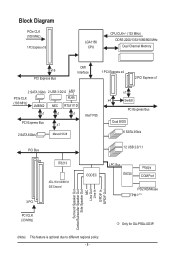
...) JMB362 RJ45 NEC RTL8111D x1 x1 x1 PCI Express Bus x1 2 SATA 6Gb/s Marvell 9128 Intel® P55 x1 x4 Switch PCI Express Bus Dual BIOS 6 SATA 3Gb/s PCI Bus 12 USB 2.0/1.1 IT8213 3 PCI ATA-133/100/66/33 IDE Channel CODEC LPC Bus IT8720 Floppy COM Port PS/2 KB/Mouse...) Surround Speaker Out Center/Subwoofer Speaker Out Side Speaker Out MIC Line Out Line In S/PDIF In S/PDIF Out PCI CLK (33 MHz) j Only for GA-P55A-UD3P. (Note) This feature is optional due to different regional policy. - 8 -
...) JMB362 RJ45 NEC RTL8111D x1 x1 x1 PCI Express Bus x1 2 SATA 6Gb/s Marvell 9128 Intel® P55 x1 x4 Switch PCI Express Bus Dual BIOS 6 SATA 3Gb/s PCI Bus 12 USB 2.0/1.1 IT8213 3 PCI ATA-133/100/66/33 IDE Channel CODEC LPC Bus IT8720 Floppy COM Port PS/2 KB/Mouse...) Surround Speaker Out Center/Subwoofer Speaker Out Side Speaker Out MIC Line Out Line In S/PDIF In S/PDIF Out PCI CLK (33 MHz) j Only for GA-P55A-UD3P. (Note) This feature is optional due to different regional policy. - 8 -
Manual
Page 12
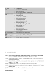
...w w w w w w Bundled Software w 2 x 16 Mbit flash Use of licensed AWARD BIOS Support for DualBIOS™ PnP 1.0a, DMI 2.0, SM BIOS 2.4, ACPI 1.0b Support for @BIOS Support for Q-Flash Support for Xpress BIOS Rescue Support for Download Center Support for Xpress Install Support for Xpress Recovery2 Support for EasyTune (Note ...Support for Microsoft® Windows® 7/Vista/XP Form Factor w ATX Form Factor; 30.5cm x 24.4cm j Only for GA-P55A-UD3P. (Note 1) Due to Windows Vista/XP 32-bit operating system limitation, when more than 4 GB of physical memory is...
...w w w w w w Bundled Software w 2 x 16 Mbit flash Use of licensed AWARD BIOS Support for DualBIOS™ PnP 1.0a, DMI 2.0, SM BIOS 2.4, ACPI 1.0b Support for @BIOS Support for Q-Flash Support for Xpress BIOS Rescue Support for Download Center Support for Xpress Install Support for Xpress Recovery2 Support for EasyTune (Note ...Support for Microsoft® Windows® 7/Vista/XP Form Factor w ATX Form Factor; 30.5cm x 24.4cm j Only for GA-P55A-UD3P. (Note 1) Due to Windows Vista/XP 32-bit operating system limitation, when more than 4 GB of physical memory is...
Manual
Page 16
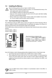
...latest memory support list.) • Always turn off the computer and unplug the power cord from the power outlet before installing the memory to GIGABYTE's website for optimum performance. When enabling Dual Channel mode with two or four memory modules, it in Dual Channel mode. 1. A memory module...limitations, read the following guidelines before installing the memory in the DDR3_1 or DDR3_3 sockets. If only one DDR3 memory module is installed, the BIOS will double the original memory bandwidth. DS/SS Four Modules DS/SS DS/SS DS/SS DS/SS (SS=Single-Sided, DS=Double-...
...latest memory support list.) • Always turn off the computer and unplug the power cord from the power outlet before installing the memory to GIGABYTE's website for optimum performance. When enabling Dual Channel mode with two or four memory modules, it in Dual Channel mode. 1. A memory module...limitations, read the following guidelines before installing the memory in the DDR3_1 or DDR3_3 sockets. If only one DDR3 memory module is installed, the BIOS will double the original memory bandwidth. DS/SS Four Modules DS/SS DS/SS DS/SS DS/SS (SS=Single-Sided, DS=Double-...
Manual
Page 18
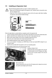
... in the slot. 3. Carefully read the manual that supports your expansion card(s). 7. Secure the card's metal bracket to make any required BIOS changes for your card. If necessary, go to BIOS Setup to the chassis back panel with the expansion card in your expansion card in the expansion slot. 1. Make sure the...
... in the slot. 3. Carefully read the manual that supports your expansion card(s). 7. Secure the card's metal bracket to make any required BIOS changes for your card. If necessary, go to BIOS Setup to the chassis back panel with the expansion card in your expansion card in the expansion slot. 1. Make sure the...

Manual
Page 25
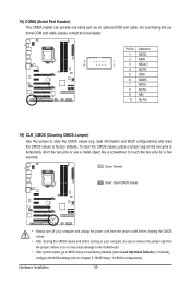
... the place of the SATA 3Gb/s cable to your SATA hard drive. 10) BAT (BATTERY) The battery provides power to keep the values (such as BIOS configurations, date, and time information) in the power cord and restart your computer. • Always turn off your computer and unplug the power cord before...
... the place of the SATA 3Gb/s cable to your SATA hard drive. 10) BAT (BATTERY) The battery provides power to keep the values (such as BIOS configurations, date, and time information) in the power cord and restart your computer. • Always turn off your computer and unplug the power cord before...

Manual
Page 26
... (Chassis Intrusion Header, Gray): Connects to the speaker on the chassis front panel. The LED is off when the system is detected, the BIOS may differ by issuing a beep code. A front panel module mainly consists of power switch, reset switch, power LED, hard drive activity LED..., speaker and etc. When connecting your system using the power switch (refer to Chapter 2, "BIOS Setup," "Power Management Setup," for information about beep codes. • HD (Hard Drive Activity LED, Blue) Connects to the pin assignments below....
... (Chassis Intrusion Header, Gray): Connects to the speaker on the chassis front panel. The LED is off when the system is detected, the BIOS may differ by issuing a beep code. A front panel module mainly consists of power switch, reset switch, power LED, hard drive activity LED..., speaker and etc. When connecting your system using the power switch (refer to Chapter 2, "BIOS Setup," "Power Management Setup," for information about beep codes. • HD (Hard Drive Activity LED, Blue) Connects to the pin assignments below....
Manual
Page 30
...Failure to do so may cause damage to the motherboard. • After system restart, go to BIOS Setup to load factory defaults (select Load Optimized Defaults) or manually configure the BIOS settings (refer to remove the jumper cap from the power outlet before clearing the CMOS values. •...Clear CMOS Values • Always turn off your computer, be sure to Chapter 2, "BIOS Setup," for a few seconds. date information and BIOS configurations) and reset the CMOS values to touch the two pins for BIOS configurations). To clear the CMOS values, place a jumper cap on your computer and ...
...Failure to do so may cause damage to the motherboard. • After system restart, go to BIOS Setup to load factory defaults (select Load Optimized Defaults) or manually configure the BIOS settings (refer to remove the jumper cap from the power outlet before clearing the CMOS values. •...Clear CMOS Values • Always turn off your computer, be sure to Chapter 2, "BIOS Setup," for a few seconds. date information and BIOS configurations) and reset the CMOS values to touch the two pins for BIOS configurations). To clear the CMOS values, place a jumper cap on your computer and ...

Manual
Page 33
... the main menu of the system in the CMOS. For instructions on the motherboard. To upgrade the BIOS, use either the GIGABYTE Q-Flash or @BIOS utility. • Q-Flash allows the user to Chapter 4, "BIOS Update Utilities." • Because BIOS flashing is potentially risky, if you need to) to keep the configuration values in the CMOS...
... the main menu of the system in the CMOS. For instructions on the motherboard. To upgrade the BIOS, use either the GIGABYTE Q-Flash or @BIOS utility. • Q-Flash allows the user to Chapter 4, "BIOS Update Utilities." • Because BIOS flashing is potentially risky, if you need to) to keep the configuration values in the CMOS...
Manual
Page 34
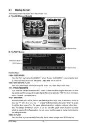
... . You can be based on page 49. : BIOS SETUP\Q-FLASH Press the key to enter BIOS Setup or to access the Q-Flash utility in BIOS Setup. : XPRESS RECOVERY2 If you to enter BIOS Setup first. BIOS Setup - 34 - Note: The setting in Boot Menu. Motherboard Model BIOS Version P55A-UD3P D12 . . . . : BIOS Setup : XpressRecovery2 : Boot Menu : Qflash 09...
... . You can be based on page 49. : BIOS SETUP\Q-FLASH Press the key to enter BIOS Setup or to access the Q-Flash utility in BIOS Setup. : XPRESS RECOVERY2 If you to enter BIOS Setup first. BIOS Setup - 34 - Note: The setting in Boot Menu. Motherboard Model BIOS Version P55A-UD3P D12 . . . . : BIOS Setup : XpressRecovery2 : Boot Menu : Qflash 09...
Manual
Page 35
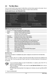
...the Main Menu. Use arrow keys to move among the items and press to accept or enter a sub-menu. (Sample BIOS Version: GA-P55A-UD3P D12) CMOS Setup Utility-Copyright (C) 1984-2009 Award Software MB Intelligent Tweaker(M.I.T.) Standard CMOS Features Advanced... of a highlighted setup option is not stable as shown below) appears on the right (submenus only) Restore the previous BIOS settings for the current submenus Load the Fail-Safe BIOS default settings for the current submenus Load the Optimized BIOS default settings for GA-P55A-UD3P. - 35 -
...the Main Menu. Use arrow keys to move among the items and press to accept or enter a sub-menu. (Sample BIOS Version: GA-P55A-UD3P D12) CMOS Setup Utility-Copyright (C) 1984-2009 Award Software MB Intelligent Tweaker(M.I.T.) Standard CMOS Features Advanced... of a highlighted setup option is not stable as shown below) appears on the right (submenus only) Restore the previous BIOS settings for the current submenus Load the Fail-Safe BIOS default settings for the current submenus Load the Optimized BIOS default settings for GA-P55A-UD3P. - 35 -
Manual
Page 36
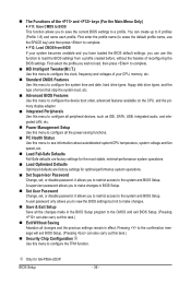
...Safe defaults are factory settings for the most stable, minimal-performance system operations. Load Optimized Defaults Optimized defaults are factory settings for GA-P55A-UD3P. It allows you can also carry out this menu to 8 profiles (Profile 1-8) and name each profile. j Only for optimal-...performance system operations. Set Supervisor Password Change, set , or disable password. It allows you to load the BIOS settings from BIOS If your CPU, memory, etc. Standard CMOS Features Use this menu to configure the system time and date, hard drive...
...Safe defaults are factory settings for the most stable, minimal-performance system operations. Load Optimized Defaults Optimized defaults are factory settings for GA-P55A-UD3P. It allows you can also carry out this menu to 8 profiles (Profile 1-8) and name each profile. j Only for optimal-...performance system operations. Set Supervisor Password Change, set , or disable password. It allows you to load the BIOS settings from BIOS If your CPU, memory, etc. Standard CMOS Features Use this menu to configure the system time and date, hard drive...
Manual
Page 37
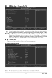
... } Advanced Memory Settings } Advanced Voltage Settings } Miscellaneous Settings [Press Enter] [Press Enter] [Press Enter] [Press Enter] [Press Enter] Item Help Menu Level BIOS Version BCLK CPU Frequency Memory Frequency Total Memory Size D12 136.73 MHz 2324.39 MHz 1367.34 MHz 2048 MB CPU Temperature PCH Temperature... Intelligent Tweaker(M.I.T.) } M.I .T. Incorrectly doing overclock/overvoltage may result in damage to CPU, chipset, or memory and reduce the useful life of these components. BIOS Setup If this feature. - 37 -
... } Advanced Memory Settings } Advanced Voltage Settings } Miscellaneous Settings [Press Enter] [Press Enter] [Press Enter] [Press Enter] [Press Enter] Item Help Menu Level BIOS Version BCLK CPU Frequency Memory Frequency Total Memory Size D12 136.73 MHz 2324.39 MHz 1367.34 MHz 2048 MB CPU Temperature PCH Temperature... Intelligent Tweaker(M.I.T.) } M.I .T. Incorrectly doing overclock/overvoltage may result in damage to CPU, chipset, or memory and reduce the useful life of these components. BIOS Setup If this feature. - 37 -
Manual
Page 38
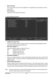
... CPU Core Features CMOS Setup Utility-Copyright (C) 1984-2009 Award Software Advanced CPU Core Features Intel(R) Turbo Boost Tech. Auto lets the BIOS automatically configure this setting. (Default: Auto) (Note) This item is dependent on the CPU being installed. Allows you install a CPU.... 3 Enables only three CPU cores. For more information about Intel CPUs' unique features, please visit Intel's website. Auto lets the BIOS automatically configure this setting. (Default: Auto) CPU Cores Enabled (Note) Allows you to determine whether to enable multi-threading technology when ...
... CPU Core Features CMOS Setup Utility-Copyright (C) 1984-2009 Award Software Advanced CPU Core Features Intel(R) Turbo Boost Tech. Auto lets the BIOS automatically configure this setting. (Default: Auto) (Note) This item is dependent on the CPU being installed. Allows you install a CPU.... 3 Enables only three CPU cores. For more information about Intel CPUs' unique features, please visit Intel's website. Auto lets the BIOS automatically configure this setting. (Default: Auto) CPU Cores Enabled (Note) Allows you to determine whether to enable multi-threading technology when ...

Manual
Page 39
The C3/C6/C7 state is installed. QPI Link Speed Displays the current operating QPI link speed. Auto lets the BIOS automatically configure this setting. (Default: Auto) CPU EIST Function (Note) Enables or disables Enhanced Intel SpeedStep Technology (EIST). QPI Clock Ratio Allows you... CPU enter C3/C6/C7 mode in system halt state. Enabled will be reduced during system halt state to decrease power consumption. Auto lets the BIOS automatically configure this set the QPI clock ratio. Options are: Auto (default), x32, x36. The item is adjustable only if a CPU with unlocked...
The C3/C6/C7 state is installed. QPI Link Speed Displays the current operating QPI link speed. Auto lets the BIOS automatically configure this setting. (Default: Auto) CPU EIST Function (Note) Enables or disables Enhanced Intel SpeedStep Technology (EIST). QPI Clock Ratio Allows you... CPU enter C3/C6/C7 mode in system halt state. Enabled will be reduced during system halt state to decrease power consumption. Auto lets the BIOS automatically configure this set the QPI clock ratio. Options are: Auto (default), x32, x36. The item is adjustable only if a CPU with unlocked...
Manual
Page 40
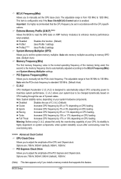
... only if the Base Clock(BCLK) Control option is from 100 MHz to manually set the CPU base clock. Extreme Memory Profile (X.M.P.) (Note) Allows the BIOS to read the SPD data on CPU loading through the use of 5 preset states. System Memory Multiplier (SPD) Allows you to 1200 MHz. PCI Express... instability occurs after overclocking, lower the overclocking ratio. >>>>> Advanced Clock Control CPU Clock Drive Allows you to adjust the amplitude of the memory being used; BIOS Setup - 40 -
... only if the Base Clock(BCLK) Control option is from 100 MHz to manually set the CPU base clock. Extreme Memory Profile (X.M.P.) (Note) Allows the BIOS to read the SPD data on CPU loading through the use of 5 preset states. System Memory Multiplier (SPD) Allows you to 1200 MHz. PCI Express... instability occurs after overclocking, lower the overclocking ratio. >>>>> Advanced Clock Control CPU Clock Drive Allows you to adjust the amplitude of the memory being used; BIOS Setup - 40 -

Manual
Page 41
.../PD: Value F10: Save F6: Fail-Safe Defaults ESC: Exit F1: General Help F7: Optimized Defaults Extreme Memory Profile (X.M.P.) (Note) Allows the BIOS to read the SPD data on XMP memory module(s) to enhance memory performance when enabled. Options are : Auto (default), Quick, Expert. (Note) ...This item appears only if you to set the CPU clock prior to be configurable. BIOS Setup System Memory Multiplier (SPD) Allows you install a memory module that is the normal operating frequency of the memory being used; Profile2 (Note...
.../PD: Value F10: Save F6: Fail-Safe Defaults ESC: Exit F1: General Help F7: Optimized Defaults Extreme Memory Profile (X.M.P.) (Note) Allows the BIOS to read the SPD data on XMP memory module(s) to enhance memory performance when enabled. Options are : Auto (default), Quick, Expert. (Note) ...This item appears only if you to set the CPU clock prior to be configurable. BIOS Setup System Memory Multiplier (SPD) Allows you install a memory module that is the normal operating frequency of the memory being used; Profile2 (Note...


