
Manual
Page 1
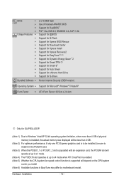
... "Installing the SATA RAID/AHCI Driver and Operating System." ) Step 3: Install the motherboard drivers and the X.H.D utiltiy After installing the operating system, insert the motherboard driver disk. Using GIGABYTE eXtreme Hard Drive (X.H.D) Instructions:(Note 2) Before launching X.H.D, make sure the newly added ...hard drive into a RAID 0 array that's been created earlier, make sure the new drive is added. eXtreme Hard Drive (X.H.D) With GIGABYTE eXtreme Hard Drive (X.H.D)(Note 1), users can quickly configure a RAIDready system for the Intel SATA controllers. For a RAID 0 array that...
... "Installing the SATA RAID/AHCI Driver and Operating System." ) Step 3: Install the motherboard drivers and the X.H.D utiltiy After installing the operating system, insert the motherboard driver disk. Using GIGABYTE eXtreme Hard Drive (X.H.D) Instructions:(Note 2) Before launching X.H.D, make sure the newly added ...hard drive into a RAID 0 array that's been created earlier, make sure the new drive is added. eXtreme Hard Drive (X.H.D) With GIGABYTE eXtreme Hard Drive (X.H.D)(Note 1), users can quickly configure a RAIDready system for the Intel SATA controllers. For a RAID 0 array that...
Manual
Page 1
GA-P55A-UD3P GA-P55A-UD3R LGA1156 socket motherboard for Intel® Core™ i7 processor family/ Intel® Core™ i5 processor family User's Manual Rev. 1002 12ME-P55AU3P-1002R
GA-P55A-UD3P GA-P55A-UD3R LGA1156 socket motherboard for Intel® Core™ i7 processor family/ Intel® Core™ i5 processor family User's Manual Rev. 1002 12ME-P55AU3P-1002R
Manual
Page 2
Motherboard GA-P55A-UD3P/GA-P55A-UD3R Oct. 16, 2009 Motherboard GA-P55A-UD3P/ GA-P55A-UD3R Oct. 16, 2009
Motherboard GA-P55A-UD3P/GA-P55A-UD3R Oct. 16, 2009 Motherboard GA-P55A-UD3P/ GA-P55A-UD3R Oct. 16, 2009
Manual
Page 3
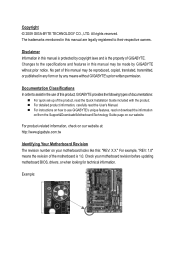
...TECHNOLOGY CO., LTD. Disclaimer Information in the use GIGABYTE's unique features, read the User's Manual. For detailed product information, carefully read or download the information on/from the Support&Downloads\Motherboard\Technology Guide page on our website. The trademarks ...www.gigabyte.com.tw Identifying Your Motherboard Revision The revision number on how to their respective owners. Check your motherboard looks like this manual are legally registered to use of GIGABYTE. Example: For instructions on your motherboard revision before updating motherboard ...
...TECHNOLOGY CO., LTD. Disclaimer Information in the use GIGABYTE's unique features, read the User's Manual. For detailed product information, carefully read or download the information on/from the Support&Downloads\Motherboard\Technology Guide page on our website. The trademarks ...www.gigabyte.com.tw Identifying Your Motherboard Revision The revision number on how to their respective owners. Check your motherboard looks like this manual are legally registered to use of GIGABYTE. Example: For instructions on your motherboard revision before updating motherboard ...
Manual
Page 4
Table of Contents Box Contents...6 Optional Items...6 GA-P55A-UD3P/GA-P55A-UD3R Motherboard Layout 7 Block Diagram...8 Chapter 1 Hardware Installation 9 1-1 Installation Precautions 9 1-2 Product Specifications 10 1-3 Installing the CPU and CPU Cooler 13 1-3-1 Installing the CPU 13 1-3-2 Installing the CPU ...
Table of Contents Box Contents...6 Optional Items...6 GA-P55A-UD3P/GA-P55A-UD3R Motherboard Layout 7 Block Diagram...8 Chapter 1 Hardware Installation 9 1-1 Installation Precautions 9 1-2 Product Specifications 10 1-3 Installing the CPU and CPU Cooler 13 1-3-1 Installing the CPU 13 1-3-2 Installing the CPU ...
Manual
Page 6
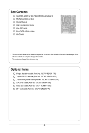
Box Contents GA-P55A-UD3P or GA-P55A-UD3R motherboard Motherboard driver disk User's Manual Quick Installation Guide One IDE cable Four SATA 3Gb/s cables I/O Shield • The box contents above are subject to change without notice. • The motherboard image is for reference only and the actual items shall depend on the product package you obtain. The box...
Box Contents GA-P55A-UD3P or GA-P55A-UD3R motherboard Motherboard driver disk User's Manual Quick Installation Guide One IDE cable Four SATA 3Gb/s cables I/O Shield • The box contents above are subject to change without notice. • The motherboard image is for reference only and the actual items shall depend on the product package you obtain. The box...
Manual
Page 7
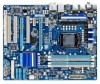
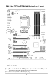
..., the PCIEX1_1 slot can only accommodate a shorter PCI Express x1 expansion card. GA-P55A-UD3P/GA-P55A-UD3R Motherboard Layout KB_USB R_SPDIF CPU_FAN ATX_12V_2X4 USB_ESATA_2 USB_ESATA_1 LGA1156 PHASE LED ATX R_USB USB30_LAN NEC AUDIO F_AUDIO JMB362 GA-P55A-UD3P GA-P55A-UD3R PCIEX1_1 (Note 1) SYS_FAN1 RTL8111D PCIEX16 PCIEX1_2 BAT CODEC PCI1 CD_IN SPDIF_I SPDIF_O PCIEX4...SATA2_0 SATA2_4 SATA2_1 SATA2_5 SATA2_2 PCI2 IDE IT8720 IT8213 PCI3 LPT COMA CLR_CMOS FDD F_USB2 F_USB1 F_PANEL j Only for GA-P55A-UD3P. (Note 1) Due to different regional policy. - 7 -
..., the PCIEX1_1 slot can only accommodate a shorter PCI Express x1 expansion card. GA-P55A-UD3P/GA-P55A-UD3R Motherboard Layout KB_USB R_SPDIF CPU_FAN ATX_12V_2X4 USB_ESATA_2 USB_ESATA_1 LGA1156 PHASE LED ATX R_USB USB30_LAN NEC AUDIO F_AUDIO JMB362 GA-P55A-UD3P GA-P55A-UD3R PCIEX1_1 (Note 1) SYS_FAN1 RTL8111D PCIEX16 PCIEX1_2 BAT CODEC PCI1 CD_IN SPDIF_I SPDIF_O PCIEX4...SATA2_0 SATA2_4 SATA2_1 SATA2_5 SATA2_2 PCI2 IDE IT8720 IT8213 PCI3 LPT COMA CLR_CMOS FDD F_USB2 F_USB1 F_PANEL j Only for GA-P55A-UD3P. (Note 1) Due to different regional policy. - 7 -
Manual
Page 9
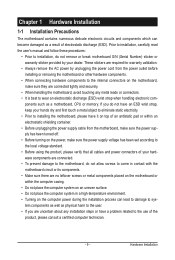
...come in a high-temperature environment. • Turning on an uneven surface. • Do not place the computer system in contact with the motherboard circuit or its components. • Make sure there are uncertain about any installation steps or have it on top of an antistatic pad or ... when handling electronic com- These stickers are required for warranty validation. • Always remove the AC power by unplugging the power cord from the motherboard, make sure the power supply has been turned off. • Before turning on the power, make sure they are connected tightly and securely. ...
...come in a high-temperature environment. • Turning on an uneven surface. • Do not place the computer system in contact with the motherboard circuit or its components. • Make sure there are uncertain about any installation steps or have it on top of an antistatic pad or ... when handling electronic com- These stickers are required for warranty validation. • Always remove the AC power by unplugging the power cord from the motherboard, make sure the power supply has been turned off. • Before turning on the power, make sure they are connected tightly and securely. ...
Manual
Page 12
... Internet Security (OEM version) Operating System w Support for Microsoft® Windows® 7/Vista/XP Form Factor w ATX Form Factor; 30.5cm x 24.4cm j Only for GA-P55A-UD3P. (Note 1) Due to Windows Vista/XP 32-bit operating system limitation, when more than 4 GB of physical memory is installed, the actual memory size... CPU/system fan speed control function is supported will depend on the CPU/system cooler you install. (Note 6) Available functions in EasyTune may differ by motherboard model.
... Internet Security (OEM version) Operating System w Support for Microsoft® Windows® 7/Vista/XP Form Factor w ATX Form Factor; 30.5cm x 24.4cm j Only for GA-P55A-UD3P. (Note 1) Due to Windows Vista/XP 32-bit operating system limitation, when more than 4 GB of physical memory is installed, the actual memory size... CPU/system fan speed control function is supported will depend on the CPU/system cooler you install. (Note 6) Available functions in EasyTune may differ by motherboard model.
Manual
Page 13
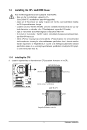
... you may occur. • Set the CPU host frequency in accordance with the CPU specifications. Hardware Installation Locate the alignment keys on the motherboard CPU socket and the notches on the CPU - 13 - LGA1156 CPU Socket Alignment Key Alignment Key Pin One Corner of the CPU Socket ...on the surface of the CPU. • Do not turn on the computer if the CPU cooler is not recommended that the motherboard supports the CPU. (Go to GIGABYTE's website for the peripherals. It is not installed, otherwise overheating and dam- The CPU cannot be set the frequency beyond hardware...
... you may occur. • Set the CPU host frequency in accordance with the CPU specifications. Hardware Installation Locate the alignment keys on the motherboard CPU socket and the notches on the CPU - 13 - LGA1156 CPU Socket Alignment Key Alignment Key Pin One Corner of the CPU Socket ...on the surface of the CPU. • Do not turn on the computer if the CPU cooler is not recommended that the motherboard supports the CPU. (Go to GIGABYTE's website for the peripherals. It is not installed, otherwise overheating and dam- The CPU cannot be set the frequency beyond hardware...
Manual
Page 14
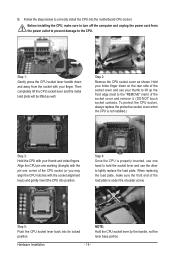
... pin one marking (triangle) with the socket alignment keys) and gently insert the CPU into position. Step 5: Push the CPU socket lever back into the motherboard CPU socket. Hold your index finger down and away from the power outlet to prevent damage to lightly replace the load plate. Step 4: Once the...
... pin one marking (triangle) with the socket alignment keys) and gently insert the CPU into position. Step 5: Push the CPU socket lever back into the motherboard CPU socket. Hold your index finger down and away from the power outlet to prevent damage to lightly replace the load plate. Step 4: Once the...
Manual
Page 15
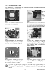
...on the push pins diagonally. If the push pin is inserted as the example cooler.) Step 1: Apply an even and thin layer of the motherboard. Inadequately removing the CPU cooler may adhere to the CPU. 1-3-2 Installing the CPU Cooler Follow the steps below to correctly install the CPU ...cooler on the motherboard. (The following procedure uses Intel® boxed cooler as the picture above shows, the installation is complete. Direction of the Arrow Sign on...
...on the push pins diagonally. If the push pin is inserted as the example cooler.) Step 1: Apply an even and thin layer of the motherboard. Inadequately removing the CPU cooler may adhere to the CPU. 1-3-2 Installing the CPU Cooler Follow the steps below to correctly install the CPU ...cooler on the motherboard. (The following procedure uses Intel® boxed cooler as the picture above shows, the installation is complete. Direction of the Arrow Sign on...
Manual
Page 16
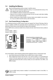
...mode. 1. The four DDR3 memory sockets are unable to insert the memory, switch the direction. 1-4-1 Dual Channel Memory Configuration This motherboard provides four DDR3 memory sockets and supports Dual Channel Technology. When enabling Dual Channel mode with two memory modules, be sure to ...begin to install the memory: • Make sure that memory of the same capacity, brand, speed, and chips be used . (Go to GIGABYTE's website for optimum performance. DS/SS - - Hardware Installation - 16 - 1-4 Installing the Memory Read the following guidelines before you are divided into...
...mode. 1. The four DDR3 memory sockets are unable to insert the memory, switch the direction. 1-4-1 Dual Channel Memory Configuration This motherboard provides four DDR3 memory sockets and supports Dual Channel Technology. When enabling Dual Channel mode with two memory modules, be sure to ...begin to install the memory: • Make sure that memory of the same capacity, brand, speed, and chips be used . (Go to GIGABYTE's website for optimum performance. DS/SS - - Hardware Installation - 16 - 1-4 Installing the Memory Read the following guidelines before you are divided into...

Manual
Page 17
..., make sure to turn off the computer and unplug the power cord from the power outlet to prevent damage to install DDR3 DIMMs on this motherboard. Step 2: The clips at both ends of the memory module. DDR3 and DDR2 DIMMs are not compatible to each other or DDR DIMMs. Be sure...
..., make sure to turn off the computer and unplug the power cord from the power outlet to prevent damage to install DDR3 DIMMs on this motherboard. Step 2: The clips at both ends of the memory module. DDR3 and DDR2 DIMMs are not compatible to each other or DDR DIMMs. Be sure...
Manual
Page 18
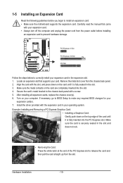
... turn off the computer and unplug the power cord from the power outlet before you begin to install an expansion card: • Make sure the motherboard supports the expansion card. Example: Installing and Removing a PCI Express Graphics Card: • Installing a Graphics Card: Gently push down on the top edge of the...
... turn off the computer and unplug the power cord from the power outlet before you begin to install an expansion card: • Make sure the motherboard supports the expansion card. Example: Installing and Removing a PCI Express Graphics Card: • Installing a Graphics Card: Gently push down on the top edge of the...

Manual
Page 19
.../2 Keyboard/Mouse Port Use this feature, ensure that your device and then remove it from the connector. Do not rock it straight out from the motherboard. • When removing the cable, pull it side to side to an external audio system that supports digital coaxial audio. Use this feature, ensure that...
.../2 Keyboard/Mouse Port Use this feature, ensure that your device and then remove it from the connector. Do not rock it straight out from the motherboard. • When removing the cable, pull it side to side to an external audio system that supports digital coaxial audio. Use this feature, ensure that...

Manual
Page 21
..., make sure your devices are compliant with the connectors you wish to connect. • Before installing the devices, be sure to the connector on the motherboard. - 21 - Hardware Installation Unplug the power cord from the power outlet to prevent damage to the devices. • After installing the device and before connecting...
..., make sure your devices are compliant with the connectors you wish to connect. • Before installing the devices, be sure to the connector on the motherboard. - 21 - Hardware Installation Unplug the power cord from the power outlet to prevent damage to the devices. • After installing the device and before connecting...
Manual
Page 22
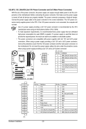
...12V and 2x10 power connectors. Before connecting the power connector, first make sure the power supply is turned off and all the components on the motherboard. If a power supply is not connected, the computer will not start. • Use of the power connector, the power supply can ... providing a 2x4 12V and a 2x12 power connector, remove the protective covers from the 12V power connector and the main power connector on the motherboard. The power connector possesses a foolproof design. Connect the power supply cable to the CPU. If the 12V power connector is used (500W or greater...
...12V and 2x10 power connectors. Before connecting the power connector, first make sure the power supply is turned off and all the components on the motherboard. If a power supply is not connected, the computer will not start. • Use of the power connector, the power supply can ... providing a 2x4 12V and a 2x12 power connector, remove the protective covers from the 12V power connector and the main power connector on the motherboard. The power connector possesses a foolproof design. Connect the power supply cable to the CPU. If the 12V power connector is used (500W or greater...

Manual
Page 23
... and the floppy disk drive cable. CPU_FAN: Pin No. The pin 1 of the cable is the ground wire). Hardware Installation The motherboard supports CPU fan speed control, which requires the use of floppy disk drives supported are not configuration jumper blocks. mended that a system ...fan be sure to locate pin 1 of different color. 3/4/5) CPU_FAN/SYS_FAN1/SYS_FAN2/PWR_FAN (Fan Headers) The motherboard has a 4-pin CPU fan header (CPU_FAN), a 4-pin (SYS_FAN2) and two 3-pin (SYS_ FAN1) system fan headers, and a 3-pin power fan ...
... and the floppy disk drive cable. CPU_FAN: Pin No. The pin 1 of the cable is the ground wire). Hardware Installation The motherboard supports CPU fan speed control, which requires the use of floppy disk drives supported are not configuration jumper blocks. mended that a system ...fan be sure to locate pin 1 of different color. 3/4/5) CPU_FAN/SYS_FAN1/SYS_FAN2/PWR_FAN (Fan Headers) The motherboard has a 4-pin CPU fan header (CPU_FAN), a 4-pin (SYS_FAN2) and two 3-pin (SYS_ FAN1) system fan headers, and a 3-pin power fan ...

Manual
Page 27
... header supports Intel High Definition audio (HD) and AC'97 audio. You may connect the audio cable that has separated connectors on both of the motherboard header. Pin No. Definition 1 2 1 MIC2_L 1 MIC 2 GND 2 GND 9 10 3 MIC2_R 3 MIC Power 4 -ACZ_DET 4 NC 5 LINE2_R 5 Line Out (R) 6 GND 6 NC 7 FAUDIO_JD 7 NC 8 No Pin... your chassis front panel audio module to work or even damage it. Hardware Installation Incorrect connection between the module connector and the motherboard header will be present on each wire instead of a single plug. Definition Pin No.
... header supports Intel High Definition audio (HD) and AC'97 audio. You may connect the audio cable that has separated connectors on both of the motherboard header. Pin No. Definition 1 2 1 MIC2_L 1 MIC 2 GND 2 GND 9 10 3 MIC2_R 3 MIC Power 4 -ACZ_DET 4 NC 5 LINE2_R 5 Line Out (R) 6 GND 6 NC 7 FAUDIO_JD 7 NC 8 No Pin... your chassis front panel audio module to work or even damage it. Hardware Installation Incorrect connection between the module connector and the motherboard header will be present on each wire instead of a single plug. Definition Pin No.


