Manual
Page 4
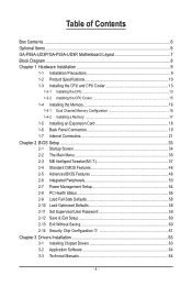
Table of Contents Box Contents...6 Optional Items...6 GA-P55A-UD3P/GA-P55A-UD3R Motherboard Layout 7 Block Diagram...8 Chapter 1 Hardware Installation 9 1-1 Installation Precautions 9 1-2 Product Specifications 10 1-3 Installing the CPU and CPU Cooler 13 1-3-1 Installing the CPU 13 1-3-2 Installing the CPU Cooler 15 1-4 Installing the Memory 16 1-4-1 Dual Channel Memory Configuration 16 1-4-2 Installing a Memory 17 1-5 Installing an Expansion Card 18 1-6 Back...
Table of Contents Box Contents...6 Optional Items...6 GA-P55A-UD3P/GA-P55A-UD3R Motherboard Layout 7 Block Diagram...8 Chapter 1 Hardware Installation 9 1-1 Installation Precautions 9 1-2 Product Specifications 10 1-3 Installing the CPU and CPU Cooler 13 1-3-1 Installing the CPU 13 1-3-2 Installing the CPU Cooler 15 1-4 Installing the Memory 16 1-4-1 Dual Channel Memory Configuration 16 1-4-2 Installing a Memory 17 1-5 Installing an Expansion Card 18 1-6 Back...
Manual
Page 8
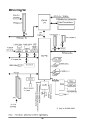
Block Diagram PCIe CLK (100 MHz) 1 PCI Express x16 LGA1156 CPU CPU CLK+/- (133 MHz) DDR3 2200/1333/1066/800 MHz Dual Channel Memory x16 PCI Express Bus DMI Interface 1 PCI Express x4 2 PCI Express x1 2 SATA 3Gb/s 2 USB 3.0/2.0 LAN PCIe CLK (100 MHz) JMB362 RJ45 NEC RTL8111D x1 ...) Surround Speaker Out Center/Subwoofer Speaker Out Side Speaker Out MIC Line Out Line In S/PDIF In S/PDIF Out PCI CLK (33 MHz) j Only for GA-P55A-UD3P. (Note) This feature is optional due to different regional policy. - 8 -
Block Diagram PCIe CLK (100 MHz) 1 PCI Express x16 LGA1156 CPU CPU CLK+/- (133 MHz) DDR3 2200/1333/1066/800 MHz Dual Channel Memory x16 PCI Express Bus DMI Interface 1 PCI Express x4 2 PCI Express x1 2 SATA 3Gb/s 2 USB 3.0/2.0 LAN PCIe CLK (100 MHz) JMB362 RJ45 NEC RTL8111D x1 ...) Surround Speaker Out Center/Subwoofer Speaker Out Side Speaker Out MIC Line Out Line In S/PDIF In S/PDIF Out PCI CLK (33 MHz) j Only for GA-P55A-UD3P. (Note) This feature is optional due to different regional policy. - 8 -
Manual
Page 9
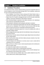
... allow screws to come in a high-temperature environment. • Turning on the computer power during the installation process can become damaged as a motherboard, CPU or memory. If you do not remove or break motherboard S/N (Serial Number) sticker or warranty sticker provided by unplugging the power cord from the power outlet before...
... allow screws to come in a high-temperature environment. • Turning on the computer power during the installation process can become damaged as a motherboard, CPU or memory. If you do not remove or break motherboard S/N (Serial Number) sticker or warranty sticker provided by unplugging the power cord from the power outlet before...
Manual
Page 10
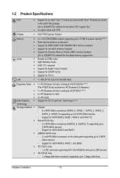
... sockets supporting up to 16 GB of system memory (Note 1) Dual channel memory architecture Support for DDR3 2200/1333/1066/800 MHz memory modules Support for non-ECC memory modules Support for Extreme Memory Profile (XMP) memory modules (Go to GIGABYTE's website for the latest memory support list.) Realtek ALC889 codec High...
... sockets supporting up to 16 GB of system memory (Note 1) Dual channel memory architecture Support for DDR3 2200/1333/1066/800 MHz memory modules Support for non-ECC memory modules Support for Extreme Memory Profile (XMP) memory modules (Go to GIGABYTE's website for the latest memory support list.) Realtek ALC889 codec High...
Manual
Page 12
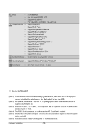
...® 7/Vista/XP Form Factor w ATX Form Factor; 30.5cm x 24.4cm j Only for GA-P55A-UD3P. (Note 1) Due to Windows Vista/XP 32-bit operating system limitation, when more than 4 GB of physical memory is installed, the actual memory size displayed will be less than 4 GB. (Note 2) For optimum performance, if only one...
...® 7/Vista/XP Form Factor w ATX Form Factor; 30.5cm x 24.4cm j Only for GA-P55A-UD3P. (Note 1) Due to Windows Vista/XP 32-bit operating system limitation, when more than 4 GB of physical memory is installed, the actual memory size displayed will be less than 4 GB. (Note 2) For optimum performance, if only one...
Manual
Page 13
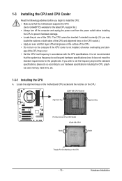
... latest CPU support list.) • Always turn on the computer if the CPU cooler is not recommended that the motherboard supports the CPU. (Go to GIGABYTE's website for the peripherals. 1-3 Installing the CPU and CPU Cooler Read the following guidelines before you begin to install the CPU: • Make sure that... if oriented incorrectly. (Or you wish to set beyond the standard specifications, please do so according to your hardware specifications including the CPU, graphics card, memory, hard drive, etc. 1-3-1 Installing the CPU A.
... latest CPU support list.) • Always turn on the computer if the CPU cooler is not recommended that the motherboard supports the CPU. (Go to GIGABYTE's website for the peripherals. 1-3 Installing the CPU and CPU Cooler Read the following guidelines before you begin to install the CPU: • Make sure that... if oriented incorrectly. (Or you wish to set beyond the standard specifications, please do so according to your hardware specifications including the CPU, graphics card, memory, hard drive, etc. 1-3-1 Installing the CPU A.
Manual
Page 16
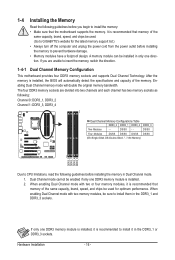
... capacity, brand, speed, and chips be used for the latest memory support list.) • Always turn off the computer and unplug the power cord from the power outlet before installing the memory to GIGABYTE's website for optimum performance. Hardware Installation - 16 - When enabling... Dual Channel mode with two or four memory modules, it in only one direction. A memory module can be sure to install it is installed...
... capacity, brand, speed, and chips be used for the latest memory support list.) • Always turn off the computer and unplug the power cord from the power outlet before installing the memory to GIGABYTE's website for optimum performance. Hardware Installation - 16 - When enabling... Dual Channel mode with two or four memory modules, it in only one direction. A memory module can be sure to install it is installed...

Manual
Page 17
... - 17 - Step 1: Note the orientation of the memory socket. Step 2: The clips at both ends of the memory, push down on the socket. Hardware Installation Place the memory module on the memory and insert it can only fit in the memory sockets. As indicated in the picture on the left, ...to correctly install your fingers on the top edge of the socket will snap into the memory socket. Spread the retaining clips at both ends of the memory module. 1-4-2 Installing a Memory Before installing a memory module, make sure to turn off the computer and unplug the power cord from the power...
... - 17 - Step 1: Note the orientation of the memory socket. Step 2: The clips at both ends of the memory, push down on the socket. Hardware Installation Place the memory module on the memory and insert it can only fit in the memory sockets. As indicated in the picture on the left, ...to correctly install your fingers on the top edge of the socket will snap into the memory socket. Spread the retaining clips at both ends of the memory module. 1-4-2 Installing a Memory Before installing a memory module, make sure to turn off the computer and unplug the power cord from the power...
Manual
Page 36
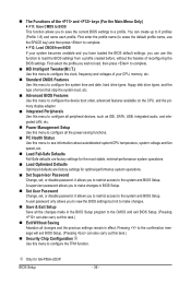
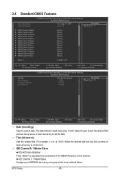
... Fail-Safe defaults are factory settings for the most stable, minimal-performance system operations. Load Optimized Defaults Optimized defaults are factory settings for GA-P55A-UD3P. First enter the profile name (to erase the default profile name, use the SPACE key) and then press to complete. F12...: Load CMOS from BIOS If your CPU, memory, etc. Standard CMOS Features Use this menu to configure the system time and date, hard drive types, floppy disk drive types, and the...
... Fail-Safe defaults are factory settings for the most stable, minimal-performance system operations. Load Optimized Defaults Optimized defaults are factory settings for GA-P55A-UD3P. First enter the profile name (to erase the default profile name, use the SPACE key) and then press to complete. F12...: Load CMOS from BIOS If your CPU, memory, etc. Standard CMOS Features Use this menu to configure the system time and date, hard drive types, floppy disk drive types, and the...
Manual
Page 37
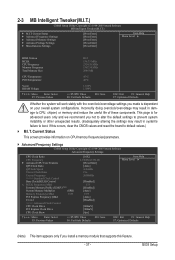
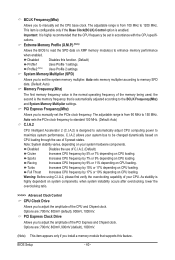
... Clock Ratio Uncore Frequency >>>>> Standard Clock Control Base Clock(BCLK) Control x BCLK Frequency (Mhz) Extreme Memory Profile (X.M.P.) (Note) System Memory Multiplier (SPD) Memory Frequency (Mhz) 1333 PCI Express Frequency (Mhz) C.I.A.2 >>>>> Advanced Clock Control CPU Clock Drive PCI Express...Press Enter] [Press Enter] [Press Enter] Item Help Menu Level BIOS Version BCLK CPU Frequency Memory Frequency Total Memory Size D12 136.73 MHz 2324.39 MHz 1367.34 MHz 2048 MB CPU Temperature PCH Temperature 45oC 40oC Vcore...
... Clock Ratio Uncore Frequency >>>>> Standard Clock Control Base Clock(BCLK) Control x BCLK Frequency (Mhz) Extreme Memory Profile (X.M.P.) (Note) System Memory Multiplier (SPD) Memory Frequency (Mhz) 1333 PCI Express Frequency (Mhz) C.I.A.2 >>>>> Advanced Clock Control CPU Clock Drive PCI Express...Press Enter] [Press Enter] [Press Enter] Item Help Menu Level BIOS Version BCLK CPU Frequency Memory Frequency Total Memory Size D12 136.73 MHz 2324.39 MHz 1367.34 MHz 2048 MB CPU Temperature PCH Temperature 45oC 40oC Vcore...
Manual
Page 40
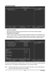
... adjust CPU computing power to maximize system performance. Disabled Disables this feature. Auto sets memory multiplier according to memory SPD data. (Default: Auto) Memory Frequency(Mhz) The first memory frequency value is highly dependent on CPU loading. As stability is the normal operating frequency...CPU frequency by 7% or 9% depending on CPU loading. Turbo Increases CPU frequency by 15% or 17% depending on XMP memory module(s) to enhance memory performance when enabled. The adjustable range is from 100 MHz to 1200 MHz. Warning: Before using C.I .A.2 allows your ...
... adjust CPU computing power to maximize system performance. Disabled Disables this feature. Auto sets memory multiplier according to memory SPD data. (Default: Auto) Memory Frequency(Mhz) The first memory frequency value is highly dependent on CPU loading. As stability is the normal operating frequency...CPU frequency by 7% or 9% depending on CPU loading. Turbo Increases CPU frequency by 15% or 17% depending on XMP memory module(s) to enhance memory performance when enabled. The adjustable range is from 100 MHz to 1200 MHz. Warning: Before using C.I .A.2 allows your ...

Manual
Page 41
...2 settings. Options are : 0ps~750ps. (Default: 0ps) Advanced Memory Settings CMOS Setup Utility-Copyright (C) 1984-2009 Award Software Advanced Memory Settings Extreme Memory Profile (X.M.P.) (Note) System Memory Multiplier (SPD) Memory Frequency (Mhz) 1333 Performance Enhance DRAM Timing Selectable (SPD) Profile DDR Voltage... feature. - 41 - Standard Lets the system operate at its basic performance level. the second is the memory frequency that supports this function. (Default) Profile1 Uses Profile 1 settings. Turbo Lets the system operate at ...
...2 settings. Options are : 0ps~750ps. (Default: 0ps) Advanced Memory Settings CMOS Setup Utility-Copyright (C) 1984-2009 Award Software Advanced Memory Settings Extreme Memory Profile (X.M.P.) (Note) System Memory Multiplier (SPD) Memory Frequency (Mhz) 1333 Performance Enhance DRAM Timing Selectable (SPD) Profile DDR Voltage... feature. - 41 - Standard Lets the system operate at its basic performance level. the second is the memory frequency that supports this function. (Default) Profile1 Uses Profile 1 settings. Turbo Lets the system operate at ...

Manual
Page 42
tRP Options are : Auto (default), 1~7. tRRD Options are : Auto (default), 1~15. When Extreme Memory Profile (X.M.P.) is set to Profile1 or Profile2, this item will display the value based on the SPD data on the CPU being used. x Round Trip ... - Rank Interleaving Options are : Auto (default), 1~63. tRCD Options are: Auto (default), 1~15. Profile QPI Voltage The value displayed here is dependent on the XMP memory. Profile DDR Voltage When using a non-XMP memory module or Extreme Memory Profile (X.M.P.) is set to Disabled, this item will display as 1.5V.
tRP Options are : Auto (default), 1~7. tRRD Options are : Auto (default), 1~15. When Extreme Memory Profile (X.M.P.) is set to Profile1 or Profile2, this item will display the value based on the SPD data on the CPU being used. x Round Trip ... - Rank Interleaving Options are : Auto (default), 1~63. tRCD Options are: Auto (default), 1~15. Profile QPI Voltage The value displayed here is dependent on the XMP memory. Profile DDR Voltage When using a non-XMP memory module or Extreme Memory Profile (X.M.P.) is set to Disabled, this item will display as 1.5V.
Manual
Page 45
... Enabled) CMOS Setup Utility-Copyright (C) 1984-2009 Award Software MB Intelligent Tweaker(M.I.T.) } M.I.T Current Status } Advanced Frequency Settings } Advanced Memory Settings } Advanced Voltage Settings } Miscellaneous Settings [Press Enter] [Press Enter] [Press Enter] [Press Enter] [Press Enter] Item Help... Menu Level BIOS Version BCLK CPU Frequency Memory Frequency Total Memory Size D12 136.73 MHz 2324.39 MHz 1367.34 MHz 2048 MB CPU Temperature PCH Temperature 45oC 40oC Vcore...
... Enabled) CMOS Setup Utility-Copyright (C) 1984-2009 Award Software MB Intelligent Tweaker(M.I.T.) } M.I.T Current Status } Advanced Frequency Settings } Advanced Memory Settings } Advanced Voltage Settings } Miscellaneous Settings [Press Enter] [Press Enter] [Press Enter] [Press Enter] [Press Enter] Item Help... Menu Level BIOS Version BCLK CPU Frequency Memory Frequency Total Memory Size D12 136.73 MHz 2324.39 MHz 1367.34 MHz 2048 MB CPU Temperature PCH Temperature 45oC 40oC Vcore...
Manual
Page 46
...-Safe Defaults ESC: Exit F1: General Help F7: Optimized Defaults CMOS Setup Utility-Copyright (C) 1984-2009 Award Software Standard CMOS Features Halt On Base Memory Extended Memory Total Memory [All, But Keyboard] 640K 1022M 1024M Item Help Menu Level Move Enter: Select F5: Previous Values +/-/PU/PD: Value F10: Save F6: Fail...
...-Safe Defaults ESC: Exit F1: General Help F7: Optimized Defaults CMOS Setup Utility-Copyright (C) 1984-2009 Award Software Standard CMOS Features Halt On Base Memory Extended Memory Total Memory [All, But Keyboard] 640K 1022M 1024M Item Help Menu Level Move Enter: Select F5: Previous Values +/-/PU/PD: Value F10: Save F6: Fail...

Manual
Page 47
... Cylinder Number of the currently installed hard drive. Precomp Write precompensation cylinder. Options are determined by using one of memory installed on the hard drive. Total Memory The total amount of the two methods below: • Auto Lets the BIOS automatically detect IDE/SATA devices during ... error. Sector Number of the IDE/SATA device on this item to None so the system will be reserved for faster system startup. Memory These fields are read-only and are : None, 360K/5.25", 1.2M/5.25", 720K/3.5", 1.44M/3.5", 2.88M/3.5". The following fields display...
... Cylinder Number of the currently installed hard drive. Precomp Write precompensation cylinder. Options are determined by using one of memory installed on the hard drive. Total Memory The total amount of the two methods below: • Auto Lets the BIOS automatically detect IDE/SATA devices during ... error. Sector Number of the IDE/SATA device on this item to None so the system will be reserved for faster system startup. Memory These fields are read-only and are : None, 360K/5.25", 1.2M/5.25", 720K/3.5", 1.44M/3.5", 2.88M/3.5". The following fields display...

Manual
Page 48
to 3 (Note) No-Execute Memory Protect (Note) Delay For HDD (Secs) Full Screen LOGO Show Backup BIOS Image to HDD Init Display First [Press Enter] [Disabled] [Hard Disk] [CDROM] [Floppy] [...
to 3 (Note) No-Execute Memory Protect (Note) Delay For HDD (Secs) Full Screen LOGO Show Backup BIOS Image to HDD Init Display First [Press Enter] [Disabled] [Hard Disk] [CDROM] [Floppy] [...

Manual
Page 49
... system boots up. porting software and system. (Default: Enabled) Delay For HDD (Secs) Allows you to determine whether to display the GIGABYTE Logo at system startup. to 3 (Note) Allows you install a CPU that supports this item to Enabled for the BIOS to initialize ...'s website. - 49 - PEG2 Sets the PCI Express graphics card on the PCIEX16 slot as Windows NT4.0. (Default: Disabled) No-Execute Memory Protect (Note) Enables or disables Intel Execute Disable Bit function. This function may enhance protection for Windows XP operating system; justable range is ...
... system boots up. porting software and system. (Default: Enabled) Delay For HDD (Secs) Allows you to determine whether to display the GIGABYTE Logo at system startup. to 3 (Note) Allows you install a CPU that supports this item to Enabled for the BIOS to initialize ...'s website. - 49 - PEG2 Sets the PCI Express graphics card on the PCIEX16 slot as Windows NT4.0. (Default: Disabled) No-Execute Memory Protect (Note) Enables or disables Intel Execute Disable Bit function. This function may enhance protection for Windows XP operating system; justable range is ...

Manual
Page 55
... operating system. Press on the +5VSB lead. AC Back Function Determines the state of the system after the return of the AC power. BIOS Setup Memory The system returns to turn on this item and set a password with 1~5 characters to its last known awake state upon the return of power from...
... operating system. Press on the +5VSB lead. AC Back Function Determines the state of the system after the return of the AC power. BIOS Setup Memory The system returns to turn on this item and set a password with 1~5 characters to its last known awake state upon the return of power from...

Manual
Page 67
... first physical drive. - 67 - Installation and Configuration: Turn on your system soon after the operating system and drivers are installed. • The amount of system memory • VESA compatible graphics card • Windows XP with Xpress Recovery cannot be restored using Xpress Recovery2. • USB hard drives are not supported. •...
... first physical drive. - 67 - Installation and Configuration: Turn on your system soon after the operating system and drivers are installed. • The amount of system memory • VESA compatible graphics card • Windows XP with Xpress Recovery cannot be restored using Xpress Recovery2. • USB hard drives are not supported. •...


