
Manual
Page 1
.... ) 1. Exits the X.H.D utility: Click Cancel to expand its capacity. Setting Up a RAID-Ready System Step 1: Configure the system BIOS Enter the system BIOS Setup program, set up all motherboard drivers, including the X.H.D utility. Using GIGABYTE eXtreme Hard Drive (X.H.D) Instructions:(Note 2) Before launching X.H.D, make sure the new drive is greater than or equal to...
.... ) 1. Exits the X.H.D utility: Click Cancel to expand its capacity. Setting Up a RAID-Ready System Step 1: Configure the system BIOS Enter the system BIOS Setup program, set up all motherboard drivers, including the X.H.D utility. Using GIGABYTE eXtreme Hard Drive (X.H.D) Instructions:(Note 2) Before launching X.H.D, make sure the new drive is greater than or equal to...

Manual
Page 3
... by copyright laws and is 1.0. Check your motherboard looks like this manual are legally registered to assist in the use GIGABYTE's unique features, read or download the information on/from the Support&Downloads\Motherboard\Technology Guide page on how to the...'s Manual. For product-related information, check on our website at: http://www.gigabyte.com.tw Identifying Your Motherboard Revision The revision number on your motherboard revision before updating motherboard BIOS, drivers, or when looking for technical information. Documentation Classifications In order to their...
... by copyright laws and is 1.0. Check your motherboard looks like this manual are legally registered to assist in the use GIGABYTE's unique features, read or download the information on/from the Support&Downloads\Motherboard\Technology Guide page on how to the...'s Manual. For product-related information, check on our website at: http://www.gigabyte.com.tw Identifying Your Motherboard Revision The revision number on your motherboard revision before updating motherboard BIOS, drivers, or when looking for technical information. Documentation Classifications In order to their...

Manual
Page 4
Table of Contents Box Contents...6 Optional Items...6 GA-P55-USB3L Motherboard Layout 7 GA-P55-USB3L Motherboard Block Diagram 8 Chapter 1 Hardware Installation 9 1-1 Installation Precautions 9 1-2 Product Specifications 10 1-3 Installing the CPU and CPU ... an Expansion Card 18 1-6 Back Panel Connectors 19 1-7 Internal Connectors 21 Chapter 2 BIOS Setup 31 2-1 Startup Screen 32 2-2 The Main Menu 33 2-3 MB Intelligent Tweaker(M.I.T 35 2-4 Standard CMOS Features 45 2-5 Advanced BIOS Features 47 2-6 Integrated Peripherals 49 2-7 Power Management Setup 52 2-8 PC Health Status ...
Table of Contents Box Contents...6 Optional Items...6 GA-P55-USB3L Motherboard Layout 7 GA-P55-USB3L Motherboard Block Diagram 8 Chapter 1 Hardware Installation 9 1-1 Installation Precautions 9 1-2 Product Specifications 10 1-3 Installing the CPU and CPU ... an Expansion Card 18 1-6 Back Panel Connectors 19 1-7 Internal Connectors 21 Chapter 2 BIOS Setup 31 2-1 Startup Screen 32 2-2 The Main Menu 33 2-3 MB Intelligent Tweaker(M.I.T 35 2-4 Standard CMOS Features 45 2-5 Advanced BIOS Features 47 2-6 Integrated Peripherals 49 2-7 Power Management Setup 52 2-8 PC Health Status ...
Manual
Page 5
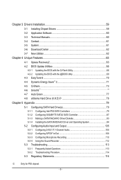
... Utilities...62 Chapter 4 Unique Features 63 4-1 Xpress Recovery2 63 4-2 BIOS Update Utilities 66 4-2-1 Updating the BIOS with the Q-Flash Utility 66 4-2-2 Updating the BIOS with the @BIOS Utility 69 4-3 EasyTune 6...70 4-4 Dynamic Energy Saver™ 2... 71 4-5 Q-Share...73 4-6 Smart 6™...74 4-7 Auto Green...77 4-8 eXtreme Hard Drive (X.H.D)j 78 Chapter 5 Appendix...79 5-1 Configuring SATA Hard Drive(s 79 5-1-1 Configuring Intel P55 SATA Controllers 79 5-1-2 Configuring GIGABYTE...
... Utilities...62 Chapter 4 Unique Features 63 4-1 Xpress Recovery2 63 4-2 BIOS Update Utilities 66 4-2-1 Updating the BIOS with the Q-Flash Utility 66 4-2-2 Updating the BIOS with the @BIOS Utility 69 4-3 EasyTune 6...70 4-4 Dynamic Energy Saver™ 2... 71 4-5 Q-Share...73 4-6 Smart 6™...74 4-7 Auto Green...77 4-8 eXtreme Hard Drive (X.H.D)j 78 Chapter 5 Appendix...79 5-1 Configuring SATA Hard Drive(s 79 5-1-1 Configuring Intel P55 SATA Controllers 79 5-1-2 Configuring GIGABYTE...
Manual
Page 8
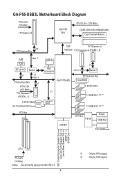
GA-P55-USB3L Motherboard Block Diagram PCIe CLK (100 MHz) 1 PCI Express x16 LGA1156 CPU CPU CLK+/- (133 MHz) DDR3 2200/1333/1066/800 MHz Dual ...) 2 SATA 3Gb/s ATA-133/100/66/33 IDE Channel PCI Bus 2 USB 3.0 NEC D720200F1 Intel® P55/H55 x4j/X1k x1 Switchj PCI Express Bus Dual BIOS 6 SATA 3Gb/s x1 14 USB 2.0/1.1j (Note) GIGABYTE SATA2 12 USB 2.0/1.1k (Note) CODEC LPC Bus IT8720 Floppy COM Port PS/2 KB/Mouse MIC (Center...) S/PDIF In S/PDIF Out 3 PCI PCI CLK (33 MHz) (Note) Two share the same port with USB 3.0. - 8 - j Only for H55 chipset. k Only for P55 chipset.
GA-P55-USB3L Motherboard Block Diagram PCIe CLK (100 MHz) 1 PCI Express x16 LGA1156 CPU CPU CLK+/- (133 MHz) DDR3 2200/1333/1066/800 MHz Dual ...) 2 SATA 3Gb/s ATA-133/100/66/33 IDE Channel PCI Bus 2 USB 3.0 NEC D720200F1 Intel® P55/H55 x4j/X1k x1 Switchj PCI Express Bus Dual BIOS 6 SATA 3Gb/s x1 14 USB 2.0/1.1j (Note) GIGABYTE SATA2 12 USB 2.0/1.1k (Note) CODEC LPC Bus IT8720 Floppy COM Port PS/2 KB/Mouse MIC (Center...) S/PDIF In S/PDIF Out 3 PCI PCI CLK (33 MHz) (Note) Two share the same port with USB 3.0. - 8 - j Only for H55 chipset. k Only for P55 chipset.
Manual
Page 12
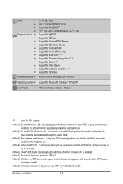
... w w w w w Bundled Software w 2 x 16 Mbit flash Use of licensed AWARD BIOS Support for DualBIOS™ PnP 1.0a, DMI 2.0, SM BIOS 2.4, ACPI 1.0b Support for @BIOS Support for Q-Flash Support for Xpress BIOS Rescue Support for Download Center Support for Xpress Install Support for Xpress Recovery2 Support for EasyTune (Note ... Support for Microsoft® Windows® 7/Vista/XP Form Factor w ATX Form Factor; 30.5cm x 19.0cm j Only for P55 chipset. (Note 1) Due to Windows 32-bit operating system limitation, when more than 4 GB of physical memory is installed, the...
... w w w w w Bundled Software w 2 x 16 Mbit flash Use of licensed AWARD BIOS Support for DualBIOS™ PnP 1.0a, DMI 2.0, SM BIOS 2.4, ACPI 1.0b Support for @BIOS Support for Q-Flash Support for Xpress BIOS Rescue Support for Download Center Support for Xpress Install Support for Xpress Recovery2 Support for EasyTune (Note ... Support for Microsoft® Windows® 7/Vista/XP Form Factor w ATX Form Factor; 30.5cm x 19.0cm j Only for P55 chipset. (Note 1) Due to Windows 32-bit operating system limitation, when more than 4 GB of physical memory is installed, the...
Manual
Page 16
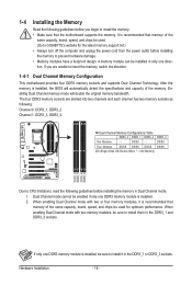
... automatically detect the specifications and capacity of the same capacity, brand, speed, and chips be installed in only one DDR3 memory module is installed, the BIOS will double the original memory bandwidth. The four DDR3 memory sockets are unable to install them in the DDR3_1 and DDR3_3 sockets. Dual Channel mode... cannot be sure to install the memory: • Make sure that memory of the memory. A memory module can be used . (Go to GIGABYTE's website for optimum performance.
... automatically detect the specifications and capacity of the same capacity, brand, speed, and chips be installed in only one DDR3 memory module is installed, the BIOS will double the original memory bandwidth. The four DDR3 memory sockets are unable to install them in the DDR3_1 and DDR3_3 sockets. Dual Channel mode... cannot be sure to install the memory: • Make sure that memory of the memory. A memory module can be used . (Go to GIGABYTE's website for optimum performance.
Manual
Page 18
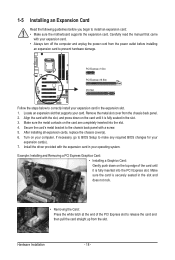
... straight up from the slot. Install the driver provided with the slot, and press down on your card. If necessary, go to BIOS Setup to make any required BIOS changes for your operating system. PCI Express x1 Slot PCI Express x16 Slot PCI Slot Follow the steps below to correctly install your...
... straight up from the slot. Install the driver provided with the slot, and press down on your card. If necessary, go to BIOS Setup to make any required BIOS changes for your operating system. PCI Express x1 Slot PCI Express x16 Slot PCI Slot Follow the steps below to correctly install your...

Manual
Page 25
... positive side should face up). • Used batteries must be used, the total the SATA 3Gb/s cable to keep the values (such as BIOS configurations, date, and time information) in the CMOS when the computer is replaced with an incorrect model. • Contact the place of explosion if... if you are not able to SATA 3Gb/s standard and are to be an even number. 9) GSATA2_6/7 (SATA 3Gb/s Connectors, Controlled by GIGABYTE SATA2) The SATA connectors conform to replace the battery by removing the battery: 1. Hardware Installation Gently remove the battery from the battery holder and ...
... positive side should face up). • Used batteries must be used, the total the SATA 3Gb/s cable to keep the values (such as BIOS configurations, date, and time information) in the CMOS when the computer is replaced with an incorrect model. • Contact the place of explosion if... if you are not able to SATA 3Gb/s standard and are to be an even number. 9) GSATA2_6/7 (SATA 3Gb/s Connectors, Controlled by GIGABYTE SATA2) The SATA connectors conform to replace the battery by removing the battery: 1. Hardware Installation Gently remove the battery from the battery holder and ...

Manual
Page 26
...panel. One single short beep will be heard if no problem is operating. The LED is on when the hard drive is detected, the BIOS may differ by issuing a beep code. This function requires a chassis with a chassis intrusion switch/sensor. The front panel design may issue beeps... (Speaker, Orange): Connects to the speaker on the chassis front panel. PWR- When connecting your system using the power switch (refer to Chapter 2, "BIOS Setup," "Power Management Setup," for information about beep codes. • HD (Hard Drive Activity LED, Blue) Connects to the hard drive activity LED on...
...panel. One single short beep will be heard if no problem is operating. The LED is on when the hard drive is detected, the BIOS may differ by issuing a beep code. This function requires a chassis with a chassis intrusion switch/sensor. The front panel design may issue beeps... (Speaker, Orange): Connects to the speaker on the chassis front panel. PWR- When connecting your system using the power switch (refer to Chapter 2, "BIOS Setup," "Power Management Setup," for information about beep codes. • HD (Hard Drive Activity LED, Blue) Connects to the hard drive activity LED on...

Manual
Page 29
... No. Failure to do so may cause damage to the motherboard. • After system restart, go to BIOS Setup to load factory defaults (select Load Optimized Defaults) or manually configure the BIOS settings (refer to USB 2.0/1.1 specification. Open: Normal Short: Clear CMOS Values • Always turn off your... pins or use a metal object like a screwdriver to factory defaults. 16) F_USB1/F_USB2/(F_USB3j) (USB Headers) The headers conform to Chapter 2, "BIOS Setup," for BIOS configurations). date information and BIOS configurations) and reset the CMOS values to touch the two pins for...
... No. Failure to do so may cause damage to the motherboard. • After system restart, go to BIOS Setup to load factory defaults (select Load Optimized Defaults) or manually configure the BIOS settings (refer to USB 2.0/1.1 specification. Open: Normal Short: Clear CMOS Values • Always turn off your... pins or use a metal object like a screwdriver to factory defaults. 16) F_USB1/F_USB2/(F_USB3j) (USB Headers) The headers conform to Chapter 2, "BIOS Setup," for BIOS configurations). date information and BIOS configurations) and reset the CMOS values to touch the two pins for...

Manual
Page 31
To upgrade the BIOS, use either the GIGABYTE Q-Flash or @BIOS utility. • Q-Flash allows the user to quickly and easily upgrade or back up BIOS without entering the operating system. • @BIOS is turned off, the battery on the motherboard. Refer to Chapter 5, "Troubleshooting," ...Refer to the "Load Optimized Defaults" section in system's failure to Chapter 4, "BIOS Update Utilities." • Because BIOS flashing is potentially risky, if you not flash the BIOS. BIOS includes a BIOS Setup program that you do it is recommended that searches and downloads the latest version...
To upgrade the BIOS, use either the GIGABYTE Q-Flash or @BIOS utility. • Q-Flash allows the user to quickly and easily upgrade or back up BIOS without entering the operating system. • @BIOS is turned off, the battery on the motherboard. Refer to Chapter 5, "Troubleshooting," ...Refer to the "Load Optimized Defaults" section in system's failure to Chapter 4, "BIOS Update Utilities." • Because BIOS flashing is potentially risky, if you not flash the BIOS. BIOS includes a BIOS Setup program that you do it is recommended that searches and downloads the latest version...
Manual
Page 32
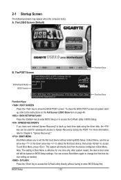
... will still be used for one time only. The POST Screen Award Modular BIOS v6.00PG, An Energy Star Ally Copyright (C) 1984-2009, Award Software, Inc. Motherboard Model BIOS Version P55-USB3L E12c . . . . : BIOS Setup : XpressRecovery2 : Boot Menu : Qflash 12/04/2009-P55-7A89TG0DC-00 Function Keys Function Keys Function Keys: : POST SCREEN Press the key...
... will still be used for one time only. The POST Screen Award Modular BIOS v6.00PG, An Energy Star Ally Copyright (C) 1984-2009, Award Software, Inc. Motherboard Model BIOS Version P55-USB3L E12c . . . . : BIOS Setup : XpressRecovery2 : Boot Menu : Qflash 12/04/2009-P55-7A89TG0DC-00 Function Keys Function Keys Function Keys: : POST SCREEN Press the key...

Manual
Page 33
...the Main Menu or a submenu, press + to access more advanced options. • When the system is displayed on the screen. Press to BIOS Load CMOS from BIOS BIOS Setup Program Function Keys Move the selection bar to select an item Execute command or enter the submenu Main Menu: Exit the... right side of function keys available for the current submenus Access the Q-Flash utility Display system information Save all the changes and exit the BIOS Setup program Save CMOS to exit the help screen (General Help) of the submenu. • If you do not find the settings...
...the Main Menu or a submenu, press + to access more advanced options. • When the system is displayed on the screen. Press to BIOS Load CMOS from BIOS BIOS Setup Program Function Keys Move the selection bar to select an item Execute command or enter the submenu Main Menu: Exit the... right side of function keys available for the current submenus Access the Q-Flash utility Display system information Save all the changes and exit the BIOS Setup program Save CMOS to exit the help screen (General Help) of the submenu. • If you do not find the settings...

Manual
Page 34
... MB Intelligent Tweaker(M.I.T.) Use this menu to configure the clock, frequency and voltages of your system becomes unstable and you have loaded the BIOS default settings, you to see information about autodetected system/CPU temperature, system voltage and fan speed, etc. Load Fail-Safe ...enter the profile name (to erase the default profile name, use this task.) Exit Without Saving Abandon all the changes made in BIOS Setup. Set User Password Change, set , or disable password. A supervisor password allows you can also carry out this function to...
... MB Intelligent Tweaker(M.I.T.) Use this menu to configure the clock, frequency and voltages of your system becomes unstable and you have loaded the BIOS default settings, you to see information about autodetected system/CPU temperature, system voltage and fan speed, etc. Load Fail-Safe ...enter the profile name (to erase the default profile name, use this task.) Exit Without Saving Abandon all the changes made in BIOS Setup. Set User Password Change, set , or disable password. A supervisor password allows you can also carry out this function to...

Manual
Page 35
Current Status This screen provides information on your overall system configurations. BIOS Setup This page is for advanced users only and we recommend you made is dependent on CPU/memory frequencies/parameters. ...Advanced Memory Settings } Advanced Voltage Settings } Miscellaneous Settings [Press Enter] [Press Enter] [Press Enter] [Press Enter] [Press Enter] Item Help Menu Level BIOS Version BCLK CPU Frequency Memory Frequency Total Memory Size E12c 133.27 MHz 2265.70 MHz 1332.71 MHz 1024 MB CPU Temperature PCH Temperature...
Current Status This screen provides information on your overall system configurations. BIOS Setup This page is for advanced users only and we recommend you made is dependent on CPU/memory frequencies/parameters. ...Advanced Memory Settings } Advanced Voltage Settings } Miscellaneous Settings [Press Enter] [Press Enter] [Press Enter] [Press Enter] [Press Enter] Item Help Menu Level BIOS Version BCLK CPU Frequency Memory Frequency Total Memory Size E12c 133.27 MHz 2265.70 MHz 1332.71 MHz 1024 MB CPU Temperature PCH Temperature...

Manual
Page 36
...Safe Defaults ESC: Exit F1: General Help F7: Optimized Defaults Intel(R) Turbo Boost Tech. This feature only works for the installed CPU. BIOS Setup - 36 - CPU Frequency Displays the current operating CPU frequency. Advanced CPU Core Features CMOS Setup Utility-Copyright (C) 1984...Core Features Intel(R) Turbo Boost Tech. For more information about Intel CPUs' unique features, please visit Intel's website. Auto lets the BIOS automatically configure this setting. (Default: Auto) (Note) This item is dependent on the CPU being installed. The adjustable range is ...
...Safe Defaults ESC: Exit F1: General Help F7: Optimized Defaults Intel(R) Turbo Boost Tech. This feature only works for the installed CPU. BIOS Setup - 36 - CPU Frequency Displays the current operating CPU frequency. Advanced CPU Core Features CMOS Setup Utility-Copyright (C) 1984...Core Features Intel(R) Turbo Boost Tech. For more information about Intel CPUs' unique features, please visit Intel's website. Auto lets the BIOS automatically configure this setting. (Default: Auto) (Note) This item is dependent on the CPU being installed. The adjustable range is ...

Manual
Page 37
... production. Uncore Clock Ratio Displays the Uncore clock ratio. ting. (Default: Auto) Bi-Directional PROCHOT (Note) Auto Enabled Disabled Lets BIOS automatically configure this setting. (Default) When the CPU or chipset detects that supports this setting. (Default: Auto) CPU EIST Function (...Note) Enables or disables Enhanced Intel SpeedStep Technology (EIST). BIOS Setup abled, the CPU core frequency and voltage will be reduced during system halt state to set - QPI Clock Ratio Allows you ...
... production. Uncore Clock Ratio Displays the Uncore clock ratio. ting. (Default: Auto) Bi-Directional PROCHOT (Note) Auto Enabled Disabled Lets BIOS automatically configure this setting. (Default) When the CPU or chipset detects that supports this setting. (Default: Auto) CPU EIST Function (...Note) Enables or disables Enhanced Intel SpeedStep Technology (EIST). BIOS Setup abled, the CPU core frequency and voltage will be reduced during system halt state to set - QPI Clock Ratio Allows you ...

Manual
Page 38
Extreme Memory Profile (X.M.P.) (Note) Allows the BIOS to read the SPD data on XMP memory module(s) to memory SPD data. (Default: Auto) Memory Frequency(Mhz) The first memory frequency value is automatically ... you to manually set the CPU base clock. The adjustable range is from 100 MHz to 600 MHz. Options are : 700mV, 800mV, 900mV (default), 1000mV. BIOS Setup - 38 - The adjustable range is from 90 MHz to 150 MHz. Options are: 700mV, 800mV (default), 900mV, 1000mV. BCLK Frequency(Mhz) Allows you to...
Extreme Memory Profile (X.M.P.) (Note) Allows the BIOS to read the SPD data on XMP memory module(s) to memory SPD data. (Default: Auto) Memory Frequency(Mhz) The first memory frequency value is automatically ... you to manually set the CPU base clock. The adjustable range is from 100 MHz to 600 MHz. Options are : 700mV, 800mV, 900mV (default), 1000mV. BIOS Setup - 38 - The adjustable range is from 90 MHz to 150 MHz. Options are: 700mV, 800mV (default), 900mV, 1000mV. BCLK Frequency(Mhz) Allows you to...

Manual
Page 39
...be configurable. DRAM Timing Selectable (SPD) Quick and Expert allows the Channel Interleaving and Rank Interleaving items to enhance memory performance when enabled. BIOS Setup Options are: Auto (default), Quick, Expert. Profile DDR Voltage When using a non-XMP memory module or Extreme Memory Profile (X.M.P.) ... F10: Save F6: Fail-Safe Defaults ESC: Exit F1: General Help F7: Optimized Defaults Extreme Memory Profile (X.M.P.) (Note) Allows the BIOS to read the SPD data on the XMP memory. (Note) This item appears only if you to set to operate at three different ...
...be configurable. DRAM Timing Selectable (SPD) Quick and Expert allows the Channel Interleaving and Rank Interleaving items to enhance memory performance when enabled. BIOS Setup Options are: Auto (default), Quick, Expert. Profile DDR Voltage When using a non-XMP memory module or Extreme Memory Profile (X.M.P.) ... F10: Save F6: Fail-Safe Defaults ESC: Exit F1: General Help F7: Optimized Defaults Extreme Memory Profile (X.M.P.) (Note) Allows the BIOS to read the SPD data on the XMP memory. (Note) This item appears only if you to set to operate at three different ...


