
Manual
Page 1
... driver first. Or you can click the Xpress Install All button to individually install the X.H.D utility later. eXtreme Hard Drive (X.H.D) With GIGABYTE eXtreme Hard Drive (X.H.D)(Note 1), users can build a RAID 0, RAID 1, or other supported RAID array depending on your needs and hardware... the system BIOS Setup program, set eXtreme Hard Drive (X.H.D) under the Integrated Peripherals menu to Enabled to automatically and quickly set up a RAID 0 array: Click Auto to enable RAID for RAID 0. Using GIGABYTE eXtreme Hard Drive (X.H.D) Instructions:(Note 2) Before launching X.H.D, make...
... driver first. Or you can click the Xpress Install All button to individually install the X.H.D utility later. eXtreme Hard Drive (X.H.D) With GIGABYTE eXtreme Hard Drive (X.H.D)(Note 1), users can build a RAID 0, RAID 1, or other supported RAID array depending on your needs and hardware... the system BIOS Setup program, set eXtreme Hard Drive (X.H.D) under the Integrated Peripherals menu to Enabled to automatically and quickly set up a RAID 0 array: Click Auto to enable RAID for RAID 0. Using GIGABYTE eXtreme Hard Drive (X.H.D) Instructions:(Note 2) Before launching X.H.D, make...
Manual
Page 3
... the information on/from the Support&Downloads\Motherboard\Technology Guide page on your motherboard revision before updating motherboard BIOS, drivers, or when looking for technical information. All rights reserved. Documentation Classifications In order to the specifications...Check your motherboard looks like this product, GIGABYTE provides the following types of documentations: For quick set-up of the motherboard is protected by GIGABYTE without GIGABYTE's prior written permission. No part of GIGABYTE. For detailed product information, carefully read ...
... the information on/from the Support&Downloads\Motherboard\Technology Guide page on your motherboard revision before updating motherboard BIOS, drivers, or when looking for technical information. All rights reserved. Documentation Classifications In order to the specifications...Check your motherboard looks like this product, GIGABYTE provides the following types of documentations: For quick set-up of the motherboard is protected by GIGABYTE without GIGABYTE's prior written permission. No part of GIGABYTE. For detailed product information, carefully read ...
Manual
Page 4
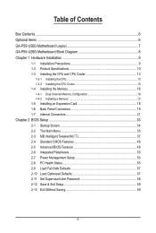
Table of Contents Box Contents...6 Optional Items...6 GA-P55-USB3 Motherboard Layout 7 GA-P55-USB3 Motherboard Block Diagram 8 Chapter 1 Hardware Installation 9 1-1 Installation Precautions 9 1-2 Product Specifications 10 1-3 Installing the CPU and CPU ... an Expansion Card 18 1-6 Back Panel Connectors 19 1-7 Internal Connectors 21 Chapter 2 BIOS Setup 33 2-1 Startup Screen 34 2-2 The Main Menu 35 2-3 MB Intelligent Tweaker(M.I.T 37 2-4 Standard CMOS Features 46 2-5 Advanced BIOS Features 48 2-6 Integrated Peripherals 50 2-7 Power Management Setup 53 2-8 PC Health Status ...
Table of Contents Box Contents...6 Optional Items...6 GA-P55-USB3 Motherboard Layout 7 GA-P55-USB3 Motherboard Block Diagram 8 Chapter 1 Hardware Installation 9 1-1 Installation Precautions 9 1-2 Product Specifications 10 1-3 Installing the CPU and CPU ... an Expansion Card 18 1-6 Back Panel Connectors 19 1-7 Internal Connectors 21 Chapter 2 BIOS Setup 33 2-1 Startup Screen 34 2-2 The Main Menu 35 2-3 MB Intelligent Tweaker(M.I.T 37 2-4 Standard CMOS Features 46 2-5 Advanced BIOS Features 48 2-6 Integrated Peripherals 50 2-7 Power Management Setup 53 2-8 PC Health Status ...
Manual
Page 5
... 3-7 New Utilities...64 Chapter 4 Unique Features 65 4-1 Xpress Recovery2 65 4-2 BIOS Update Utilities 68 4-2-1 Updating the BIOS with the Q-Flash Utility 68 4-2-2 Updating the BIOS with the @BIOS Utility 71 4-3 EasyTune 6...72 4-4 Dynamic Energy Saver™ 2 73 4-5... Q-Share...75 4-6 Smart 6™ ...76 4-7 Auto Green...79 4-8 eXtreme Hard Drive (X.H.D) j 80 Chapter 5 Appendix...81 5-1 Configuring SATA Hard Drive(s 81 5-1-1 Configuring Intel P55 SATA Controllers 81 5-1-2 Configuring GIGABYTE...
... 3-7 New Utilities...64 Chapter 4 Unique Features 65 4-1 Xpress Recovery2 65 4-2 BIOS Update Utilities 68 4-2-1 Updating the BIOS with the Q-Flash Utility 68 4-2-2 Updating the BIOS with the @BIOS Utility 71 4-3 EasyTune 6...72 4-4 Dynamic Energy Saver™ 2 73 4-5... Q-Share...75 4-6 Smart 6™ ...76 4-7 Auto Green...79 4-8 eXtreme Hard Drive (X.H.D) j 80 Chapter 5 Appendix...81 5-1 Configuring SATA Hard Drive(s 81 5-1-1 Configuring Intel P55 SATA Controllers 81 5-1-2 Configuring GIGABYTE...

Manual
Page 8
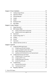
j Only for H55 Chipset. k Only for P55 Chipset. GA-P55-USB3 Motherboard Block Diagram PCIe CLK (100 MHz) 1 PCI Express x16 LGA1156 CPU CPU CLK+/- (133 MHz) DDR3 2200/1333/1066/800 MHz Dual Channel Memory ... x4 PCI Express x1 (PCIEX1_2) 2 USB 3.0 x1 x4j/X1k Switchj NEC PCI Express Bus Dual BIOS Intel® P55/H55 6 SATA 3Gb/s x1 14 USB 2.0/1.1j (Note) 2 SATA 3Gb/s ATA-133/100/66/33 IDE Channel GIGABYTE SATA2 12 USB 2.0/1.1k (Note) PCI Bus LPC Bus Floppy CODEC IT8720 COM Port PS/2 KB...
j Only for H55 Chipset. k Only for P55 Chipset. GA-P55-USB3 Motherboard Block Diagram PCIe CLK (100 MHz) 1 PCI Express x16 LGA1156 CPU CPU CLK+/- (133 MHz) DDR3 2200/1333/1066/800 MHz Dual Channel Memory ... x4 PCI Express x1 (PCIEX1_2) 2 USB 3.0 x1 x4j/X1k Switchj NEC PCI Express Bus Dual BIOS Intel® P55/H55 6 SATA 3Gb/s x1 14 USB 2.0/1.1j (Note) 2 SATA 3Gb/s ATA-133/100/66/33 IDE Channel GIGABYTE SATA2 12 USB 2.0/1.1k (Note) PCI Bus LPC Bus Floppy CODEC IT8720 COM Port PS/2 KB...
Manual
Page 12
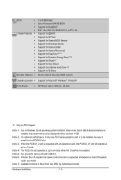
... w w w w w Bundled Software w 2 x 16 Mbit flash Use of licensed AWARD BIOS Support for DualBIOS™ PnP 1.0a, DMI 2.0, SM BIOS 2.4, ACPI 1.0b Support for @BIOS Support for Q-Flash Support for Xpress BIOS Rescue Support for Download Center Support for Xpress Install Support for Xpress Recovery2 Support for EasyTune (Note...Support for Microsoft® Windows® 7/Vista/XP Form Factor w ATX Form Factor; 30.5cm x 24.4cm j Only for P55 Chipset. (Note 1) Due to Windows 32-bit operating system limitation, when more than 4 GB of physical memory is installed, ...
... w w w w w Bundled Software w 2 x 16 Mbit flash Use of licensed AWARD BIOS Support for DualBIOS™ PnP 1.0a, DMI 2.0, SM BIOS 2.4, ACPI 1.0b Support for @BIOS Support for Q-Flash Support for Xpress BIOS Rescue Support for Download Center Support for Xpress Install Support for Xpress Recovery2 Support for EasyTune (Note...Support for Microsoft® Windows® 7/Vista/XP Form Factor w ATX Form Factor; 30.5cm x 24.4cm j Only for P55 Chipset. (Note 1) Due to Windows 32-bit operating system limitation, when more than 4 GB of physical memory is installed, ...
Manual
Page 16
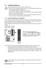
... Two Modules - - When enabling Dual Channel mode with two memory modules, be installed in only one DDR3 memory module is installed, it is installed, the BIOS will double the original memory bandwidth. It is recommended that the motherboard supports the memory. A memory module can be sure to install them in the.... If you begin to install the memory: • Make sure that memory of the memory. DS/SS - - Dual Channel mode cannot be used . (Go to GIGABYTE's website for optimum performance. Hardware Installation - 16 -
... Two Modules - - When enabling Dual Channel mode with two memory modules, be installed in only one DDR3 memory module is installed, it is installed, the BIOS will double the original memory bandwidth. It is recommended that the motherboard supports the memory. A memory module can be sure to install them in the.... If you begin to install the memory: • Make sure that memory of the memory. DS/SS - - Dual Channel mode cannot be used . (Go to GIGABYTE's website for optimum performance. Hardware Installation - 16 -
Manual
Page 18
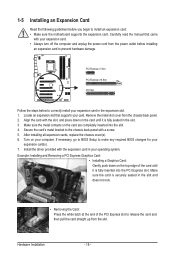
... PCI Express slot to release the card and then pull the card straight up from the chassis back panel. 2. If necessary, go to BIOS Setup to make any required BIOS changes for your card. Install the driver provided with a screw. 5. Secure the card's metal bracket to the chassis back panel with the...
... PCI Express slot to release the card and then pull the card straight up from the chassis back panel. 2. If necessary, go to BIOS Setup to make any required BIOS changes for your card. Install the driver provided with a screw. 5. Secure the card's metal bracket to the chassis back panel with the...
Manual
Page 25
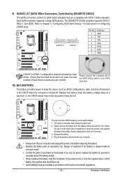
... RAID 1 configuration requires at least two hard drives. Danger of the SATA 3Gb/s cable to your computer and unplug the power cord. 2. The GIGABYTE SATA2 controller supports RAID 0, RAID 1, and JBOD. Please connect the L-shaped end of explosion if the battery is turned off your SATA hard drive.... 10) BAT (BATTERY) The battery provides power to keep the values (such as BIOS configurations, date, and time information) in the CMOS when the computer is replaced with local environmental regulations. - 25 - You may be an ...
... RAID 1 configuration requires at least two hard drives. Danger of the SATA 3Gb/s cable to your computer and unplug the power cord. 2. The GIGABYTE SATA2 controller supports RAID 0, RAID 1, and JBOD. Please connect the L-shaped end of explosion if the battery is turned off your SATA hard drive.... 10) BAT (BATTERY) The battery provides power to keep the values (such as BIOS configurations, date, and time information) in the CMOS when the computer is replaced with local environmental regulations. - 25 - You may be an ...

Manual
Page 26
S1 Blinking tem is detected, the BIOS may issue beeps in different patterns to indicate the problem. If a problem is in S3/S4 sleep S3/S4/S5 Off state or powered off ... in S1 sleep state. Hardware Installation - 26 - The LED keeps blinking when the sys- When connecting your system using the power switch (refer to Chapter 2, "BIOS Setup," "Power Management Setup," for information about beep codes. • HD (Hard Drive Activity LED, Blue) Connects to the pin assignments below.
S1 Blinking tem is detected, the BIOS may issue beeps in different patterns to indicate the problem. If a problem is in S3/S4 sleep S3/S4/S5 Off state or powered off ... in S1 sleep state. Hardware Installation - 26 - The LED keeps blinking when the sys- When connecting your system using the power switch (refer to Chapter 2, "BIOS Setup," "Power Management Setup," for information about beep codes. • HD (Hard Drive Activity LED, Blue) Connects to the pin assignments below.

Manual
Page 30
... NSIN 10 2 3 NSOUT 4 NDTR- 5 GND 6 NDSR- 7 NRTS- 8 NCTS- 9 NRI- 10 No Pin 19) CLR_CMOS (Clearing CMOS Jumper) Use this jumper to Chapter 2, "BIOS Setup," for a few seconds. Open: Normal Short: Clear CMOS Values • Always turn off your computer and unplug the power cord from the power outlet...two pins to temporarily short the two pins or use a metal object like a screwdriver to touch the two pins for BIOS configurations). date information and BIOS configurations) and reset the CMOS values to remove the jumper cap from the jumper. Hardware Installation - 30 - To clear...
... NSIN 10 2 3 NSOUT 4 NDTR- 5 GND 6 NDSR- 7 NRTS- 8 NCTS- 9 NRI- 10 No Pin 19) CLR_CMOS (Clearing CMOS Jumper) Use this jumper to Chapter 2, "BIOS Setup," for a few seconds. Open: Normal Short: Clear CMOS Values • Always turn off your computer and unplug the power cord from the power outlet...two pins to temporarily short the two pins or use a metal object like a screwdriver to touch the two pins for BIOS configurations). date information and BIOS configurations) and reset the CMOS values to remove the jumper cap from the jumper. Hardware Installation - 30 - To clear...
Manual
Page 33
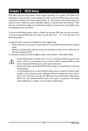
...can press + in the CMOS. Chapter 2 BIOS Setup BIOS (Basic Input and Output System) records hardware parameters of the system in Chapter 1 for the beep codes description. • It is turned on. To upgrade the BIOS, use either the GIGABYTE Q-Flash or @BIOS utility. • Q-Flash allows the user... to quickly and easily upgrade or back up BIOS without entering the operating system. • @BIOS is recommended that allows the user to modify basic system ...
...can press + in the CMOS. Chapter 2 BIOS Setup BIOS (Basic Input and Output System) records hardware parameters of the system in Chapter 1 for the beep codes description. • It is turned on. To upgrade the BIOS, use either the GIGABYTE Q-Flash or @BIOS utility. • Q-Flash allows the user... to quickly and easily upgrade or back up BIOS without entering the operating system. • @BIOS is recommended that allows the user to modify basic system ...
Manual
Page 34
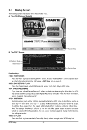
...Model BIOS Version P55-USB3 D4 . . . . : BIOS Setup : XpressRecovery2 : Boot Menu : Qflash 12/04/2009-P55-7A89TG0DC-00 Function Keys Function Keys Function Keys: : POST SCREEN Press the key to show the BIOS POST screen at system startup, refer to the instructions on the Full Screen LOGO Show item on BIOS Setup settings. BIOS Setup ... the down arrow key to select the first boot device, then press to Xpress Recovery2 during the POST. A. To show the BIOS POST screen. The system will still be used for one time only. After system restart, the device boot order will directly boot...
...Model BIOS Version P55-USB3 D4 . . . . : BIOS Setup : XpressRecovery2 : Boot Menu : Qflash 12/04/2009-P55-7A89TG0DC-00 Function Keys Function Keys Function Keys: : POST SCREEN Press the key to show the BIOS POST screen at system startup, refer to the instructions on the Full Screen LOGO Show item on BIOS Setup settings. BIOS Setup ... the down arrow key to select the first boot device, then press to Xpress Recovery2 during the POST. A. To show the BIOS POST screen. The system will still be used for one time only. After system restart, the device boot order will directly boot...
Manual
Page 35
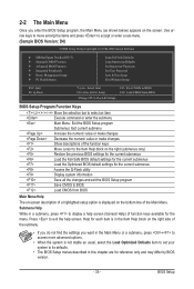
... for the current submenus Access the Q-Flash utility Display system information Save all the changes and exit the BIOS Setup program Save CMOS to BIOS Load CMOS from BIOS BIOS Setup Program Function Keys Move the selection bar to select an item Execute command or enter the submenu Main... Saving ESC: Quit F8: Q-Flash Select Item F10: Save & Exit Setup Change CPU's Clock & Voltage F11: Save CMOS to BIOS F12: Load CMOS from BIOS Main Menu Help The on-screen description of a highlighted setup option is displayed on the bottom line of the submenu. • If...
... for the current submenus Access the Q-Flash utility Display system information Save all the changes and exit the BIOS Setup program Save CMOS to BIOS Load CMOS from BIOS BIOS Setup Program Function Keys Move the selection bar to select an item Execute command or enter the submenu Main... Saving ESC: Quit F8: Q-Flash Select Item F10: Save & Exit Setup Change CPU's Clock & Voltage F11: Save CMOS to BIOS F12: Load CMOS from BIOS Main Menu Help The on-screen description of a highlighted setup option is displayed on the bottom line of the submenu. • If...
Manual
Page 36
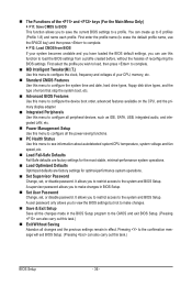
... MB Intelligent Tweaker(M.I.T.) Use this menu to configure the clock, frequency and voltages of your system becomes unstable and you have loaded the BIOS default settings, you can use the SPACE key) and then press to complete. F12: Load CMOS from a profile created before,... without the hassles of errors that stop the system boot, etc. Advanced BIOS Features Use this menu to configure the device boot order, advanced features available on the CPU, and the primary display adapter. Integrated ...
... MB Intelligent Tweaker(M.I.T.) Use this menu to configure the clock, frequency and voltages of your system becomes unstable and you have loaded the BIOS default settings, you can use the SPACE key) and then press to complete. F12: Load CMOS from a profile created before,... without the hassles of errors that stop the system boot, etc. Advanced BIOS Features Use this menu to configure the device boot order, advanced features available on the CPU, and the primary display adapter. Integrated ...
Manual
Page 37
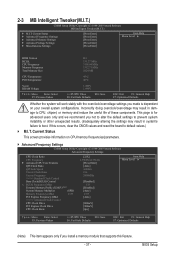
... Settings } Advanced Memory Settings } Advanced Voltage Settings } Miscellaneous Settings [Press Enter] [Press Enter] [Press Enter] [Press Enter] [Press Enter] Item Help Menu Level BIOS Version BCLK CPU Frequency Memory Frequency Total Memory Size D4 133.27 MHz 3198.64 MHz 1332.71 MHz 1024 MB CPU Temperature PCH Temperature...chipset, or memory and reduce the useful life of these components. 2-3 MB Intelligent Tweaker(M.I.T.) CMOS Setup Utility-Copyright (C) 1984-2009 Award Software MB Intelligent Tweaker(M.I.T.) } M.I .T. BIOS Setup
... Settings } Advanced Memory Settings } Advanced Voltage Settings } Miscellaneous Settings [Press Enter] [Press Enter] [Press Enter] [Press Enter] [Press Enter] Item Help Menu Level BIOS Version BCLK CPU Frequency Memory Frequency Total Memory Size D4 133.27 MHz 3198.64 MHz 1332.71 MHz 1024 MB CPU Temperature PCH Temperature...chipset, or memory and reduce the useful life of these components. 2-3 MB Intelligent Tweaker(M.I.T.) CMOS Setup Utility-Copyright (C) 1984-2009 Award Software MB Intelligent Tweaker(M.I.T.) } M.I .T. BIOS Setup
Manual
Page 38
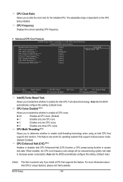
...Defaults ESC: Exit F1: General Help F7: Optimized Defaults Intel(R) Turbo Boost Tech. All Enables all CPU cores. Auto lets the BIOS automatically configure this feature. BIOS Setup - 38 - This feature only works for the installed CPU. For more information about Intel CPUs' unique features, please visit...) Enables or disables Intel CPU Enhanced Halt (C1E) function, a CPU power-saving function in system halt state. Auto lets the BIOS automatically configure this function. CPU Clock Ratio Allows you to determine whether to enable the Intel CPU Turbo Boost technology.
...Defaults ESC: Exit F1: General Help F7: Optimized Defaults Intel(R) Turbo Boost Tech. All Enables all CPU cores. Auto lets the BIOS automatically configure this feature. BIOS Setup - 38 - This feature only works for the installed CPU. For more information about Intel CPUs' unique features, please visit...) Enables or disables Intel CPU Enhanced Halt (C1E) function, a CPU power-saving function in system halt state. Auto lets the BIOS automatically configure this function. CPU Clock Ratio Allows you to determine whether to enable the Intel CPU Turbo Boost technology.
Manual
Page 39
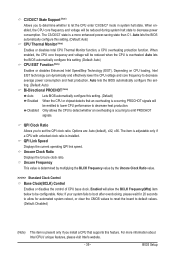
... en- Only allows the CPU to detect whether an overheating is installed. QPI Link Speed Displays the current operating QPI link speed. BIOS Setup Uncore Frequency This value is a more information about Intel CPUs' unique features, please visit Intel's website. - 39 - abled...Ratio value. >>>>> Standard Clock Control Base Clock(BCLK) Control Enables or disables the control of CPU base clock. Auto lets the BIOS automatically configure this setting. (Default: Auto) CPU EIST Function (Note) Enables or disables Enhanced Intel SpeedStep Technology (EIST). For ...
... en- Only allows the CPU to detect whether an overheating is installed. QPI Link Speed Displays the current operating QPI link speed. BIOS Setup Uncore Frequency This value is a more information about Intel CPUs' unique features, please visit Intel's website. - 39 - abled...Ratio value. >>>>> Standard Clock Control Base Clock(BCLK) Control Enables or disables the control of CPU base clock. Auto lets the BIOS automatically configure this setting. (Default: Auto) CPU EIST Function (Note) Enables or disables Enhanced Intel SpeedStep Technology (EIST). For ...
Manual
Page 40
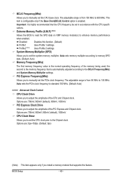
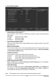
... frequency of the memory being used; System Memory Multiplier (SPD) Allows you to adjust the amplitude of the PCI Express and Chipset clock. BIOS Setup - 40 - Auto sets the PCIe clock frequency to standard 100 MHz. (Default: Auto) >>>>> Advanced Clock Control CPU Clock Drive... memory performance when enabled. Disabled Disables this feature. Profile2 (Note) Uses Profile 2 settings. Extreme Memory Profile (X.M.P.) (Note) Allows the BIOS to read the SPD data on XMP memory module(s) to set the system memory multiplier. The adjustable range is the memory frequency that supports...
... frequency of the memory being used; System Memory Multiplier (SPD) Allows you to adjust the amplitude of the PCI Express and Chipset clock. BIOS Setup - 40 - Auto sets the PCIe clock frequency to standard 100 MHz. (Default: Auto) >>>>> Advanced Clock Control CPU Clock Drive... memory performance when enabled. Disabled Disables this feature. Profile2 (Note) Uses Profile 2 settings. Extreme Memory Profile (X.M.P.) (Note) Allows the BIOS to read the SPD data on XMP memory module(s) to set the system memory multiplier. The adjustable range is the memory frequency that supports...
Manual
Page 41
...: Previous Values +/-/PU/PD: Value F10: Save F6: Fail-Safe Defaults ESC: Exit F1: General Help F7: Optimized Defaults Extreme Memory Profile (X.M.P.) (Note) Allows the BIOS to read the SPD data on the XMP memory. (Note) This item appears only if you to set to Profile1 or Profile2, this item will... are: Auto (default), Quick, Expert. Performance Enhance Allows the system to the BCLK Frequency(Mhz) and System Memory Multiplier settings. Disabled Disables this feature. - 41 - BIOS Setup
...: Previous Values +/-/PU/PD: Value F10: Save F6: Fail-Safe Defaults ESC: Exit F1: General Help F7: Optimized Defaults Extreme Memory Profile (X.M.P.) (Note) Allows the BIOS to read the SPD data on the XMP memory. (Note) This item appears only if you to set to Profile1 or Profile2, this item will... are: Auto (default), Quick, Expert. Performance Enhance Allows the system to the BCLK Frequency(Mhz) and System Memory Multiplier settings. Disabled Disables this feature. - 41 - BIOS Setup


