Manual
Page 3
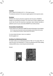
.... For product-related information, check on our website at: http://www.gigabyte.com Identifying Your Motherboard Revision The revision number on your motherboard revision before updating motherboard BIOS, drivers, or when looking for technical information. Check your motherboard looks ...like this manual may be made by any form or by GIGABYTE without GIGABYTE's prior written permission. Copyright © 2011 GIGA...
.... For product-related information, check on our website at: http://www.gigabyte.com Identifying Your Motherboard Revision The revision number on your motherboard revision before updating motherboard BIOS, drivers, or when looking for technical information. Check your motherboard looks ...like this manual may be made by any form or by GIGABYTE without GIGABYTE's prior written permission. Copyright © 2011 GIGA...
Manual
Page 4
Table of Contents Box Contents...6 Optional Items...6 GA-P41T-D3P Motherboard Layout 7 GA-P41T-D3P Motherboard Block Diagram 8 Chapter 1 Hardware Installation 9 1-1 Installation Precautions 9 1-2 Product Specifications 10 1-3 Installing the CPU and CPU ... an Expansion Card 18 1-6 Back Panel Connectors 19 1-7 Internal Connectors 21 Chapter 2 BIOS Setup 29 2-1 Startup Screen 30 2-2 The Main Menu 31 2-3 MB Intelligent Tweaker(M.I.T 33 2-4 Standard CMOS Features 40 2-5 Advanced BIOS Features 42 2-6 Integrated Peripherals 45 2-7 Power Management Setup 48 2-8 PnP/PCI Configurations ...
Table of Contents Box Contents...6 Optional Items...6 GA-P41T-D3P Motherboard Layout 7 GA-P41T-D3P Motherboard Block Diagram 8 Chapter 1 Hardware Installation 9 1-1 Installation Precautions 9 1-2 Product Specifications 10 1-3 Installing the CPU and CPU ... an Expansion Card 18 1-6 Back Panel Connectors 19 1-7 Internal Connectors 21 Chapter 2 BIOS Setup 29 2-1 Startup Screen 30 2-2 The Main Menu 31 2-3 MB Intelligent Tweaker(M.I.T 33 2-4 Standard CMOS Features 40 2-5 Advanced BIOS Features 42 2-6 Integrated Peripherals 45 2-7 Power Management Setup 48 2-8 PnP/PCI Configurations ...
Manual
Page 5
... 56 3-4 Contact...57 3-5 System...57 3-6 Download Center 58 3-7 New Utilities...58 Chapter 4 Unique Features 59 4-1 Xpress Recovery2 59 4-2 BIOS Update Utilities 62 4-2-1 Updating the BIOS with the Q-Flash Utility 62 4-2-2 Updating the BIOS with the @BIOS Utility 65 4-3 EasyTune 6...66 4-4 Easy Energy Saver 67 4-5 Q-Share...69 4-6 SMART Recovery 70 Chapter 5 Appendix...71 5-1 Configuring Audio...
... 56 3-4 Contact...57 3-5 System...57 3-6 Download Center 58 3-7 New Utilities...58 Chapter 4 Unique Features 59 4-1 Xpress Recovery2 59 4-2 BIOS Update Utilities 62 4-2-1 Updating the BIOS with the Q-Flash Utility 62 4-2-2 Updating the BIOS with the @BIOS Utility 65 4-3 EasyTune 6...66 4-4 Easy Energy Saver 67 4-5 Q-Share...69 4-6 SMART Recovery 70 Chapter 5 Appendix...71 5-1 Configuring Audio...
Manual
Page 8
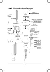
GA-P41T-D3P Motherboard Block Diagram PCIe CLK (100 MHz) 1 PCI Express x16 x16 PCI Express x16 3 PCI Express x1 PCIe CLK (100 MHz) x1 x1 x1 PCI ... MHz) Host Interface Intel® G41 DDR3 1333(O.C.)/1066/800 MHz Dual Channel Memory MCH CLK (333/266/200 MHz) Intel® ICH7 CODEC Dual BIOS ATA-100/66/33 IDE Channel 4 SATA 3Gb/s 8 USB 2.0/1.1 iTE IT8718 Floppy LPT COM Port PS/2 KB/Mouse MIC (Center/Subwoofer Speaker Out) Line-Out...
GA-P41T-D3P Motherboard Block Diagram PCIe CLK (100 MHz) 1 PCI Express x16 x16 PCI Express x16 3 PCI Express x1 PCIe CLK (100 MHz) x1 x1 x1 PCI ... MHz) Host Interface Intel® G41 DDR3 1333(O.C.)/1066/800 MHz Dual Channel Memory MCH CLK (333/266/200 MHz) Intel® ICH7 CODEC Dual BIOS ATA-100/66/33 IDE Channel 4 SATA 3Gb/s 8 USB 2.0/1.1 iTE IT8718 Floppy LPT COM Port PS/2 KB/Mouse MIC (Center/Subwoofer Speaker Out) Line-Out...

Manual
Page 11
Hardware Installation Internal Connectors Back Panel Connectors I/O Hardware Monitor BIOS ŠŠ 1 x 24-pin ATX main power connector ŠŠ 1 x 4-pin ATX 12V power connector ŠŠ 1 x floppy disk drive connector ŠŠ 1 x IDE connector &#... CPU fan speed control function is supported will depend on the CPU cooler you install. ŠŠ 2 x 8 Mbit flash ŠŠ Use of licensed AWARD BIOS ŠŠ Support for DualBIOS™ ŠŠ PnP 1.0a, DMI 2.0, SM...
Hardware Installation Internal Connectors Back Panel Connectors I/O Hardware Monitor BIOS ŠŠ 1 x 24-pin ATX main power connector ŠŠ 1 x 4-pin ATX 12V power connector ŠŠ 1 x floppy disk drive connector ŠŠ 1 x IDE connector &#... CPU fan speed control function is supported will depend on the CPU cooler you install. ŠŠ 2 x 8 Mbit flash ŠŠ Use of licensed AWARD BIOS ŠŠ Support for DualBIOS™ ŠŠ PnP 1.0a, DMI 2.0, SM...
Manual
Page 12
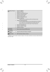
Hardware Installation - 12 - Unique Features ŠŠ Support for @BIOS ŠŠ Support for Q-Flash ŠŠ Support for Xpress BIOS Rescue ŠŠ Support for Download Center ŠŠ Support for Xpress Install ŠŠ Support for Xpress Recovery2 ŠŠ Support for ... version) Operating System ŠŠ Support for Microsoft® Windows 7/Vista/XP Form Factor ŠŠ ATX Form Factor; 30.5cm x 19.4cm * GIGABYTE reserves the right to make any changes to the product specifications and product-related information without prior notice.
Hardware Installation - 12 - Unique Features ŠŠ Support for @BIOS ŠŠ Support for Q-Flash ŠŠ Support for Xpress BIOS Rescue ŠŠ Support for Download Center ŠŠ Support for Xpress Install ŠŠ Support for Xpress Recovery2 ŠŠ Support for ... version) Operating System ŠŠ Support for Microsoft® Windows 7/Vista/XP Form Factor ŠŠ ATX Form Factor; 30.5cm x 19.4cm * GIGABYTE reserves the right to make any changes to the product specifications and product-related information without prior notice.
Manual
Page 16
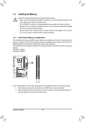
... DDR3_1 DDR3_2 Due to chipset limitation, read the following guidelines before installing the memory in only one DDR3 memory module is installed, the BIOS will double the original memory bandwidth. Dual Channel mode cannot be enabled if only one direction. After the memory is installed. 2. Enabling...the specifications and capacity of the same capacity, brand, speed, and chips be used . A memory module can be used . (Go to GIGABYTE's website for the latest supported memory speeds and memory modules.) • Always turn off the computer and unplug the power cord from the ...
... DDR3_1 DDR3_2 Due to chipset limitation, read the following guidelines before installing the memory in only one DDR3 memory module is installed, the BIOS will double the original memory bandwidth. Dual Channel mode cannot be enabled if only one direction. After the memory is installed. 2. Enabling...the specifications and capacity of the same capacity, brand, speed, and chips be used . A memory module can be used . (Go to GIGABYTE's website for the latest supported memory speeds and memory modules.) • Always turn off the computer and unplug the power cord from the ...
Manual
Page 18
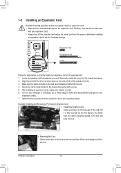
... cover from the slot. Locate an expansion slot that came with the expansion card in the expansion slot. 1. If necessary, go to BIOS Setup to make any required BIOS changes for your computer. 1-5 Installing an Expansion Card Read the following guidelines before installing an expansion card to prevent hardware damage. After installing...
... cover from the slot. Locate an expansion slot that came with the expansion card in the expansion slot. 1. If necessary, go to BIOS Setup to make any required BIOS changes for your computer. 1-5 Installing an Expansion Card Read the following guidelines before installing an expansion card to prevent hardware damage. After installing...

Manual
Page 25
...• CI (Chassis Intrusion Header): Connects to the pin assignments below. When connecting your system using the power switch (refer to Chapter 2, "BIOS Setup," "Power Management Setup," for information about beep codes. • HD (Hard Drive Activity LED) Connects to the hard drive activity LED on..., power LED, hard drive activity LED, speaker and etc. Hardware Installation SPEAK+ PWR+ CI+ CI- S1 Blinking tem is detected, the BIOS may differ by issuing a beep code. The front panel design may issue beeps in S1 sleep state. G.QBOFM Speaker Power Switch Message/Power...
...• CI (Chassis Intrusion Header): Connects to the pin assignments below. When connecting your system using the power switch (refer to Chapter 2, "BIOS Setup," "Power Management Setup," for information about beep codes. • HD (Hard Drive Activity LED) Connects to the hard drive activity LED on..., power LED, hard drive activity LED, speaker and etc. Hardware Installation SPEAK+ PWR+ CI+ CI- S1 Blinking tem is detected, the BIOS may differ by issuing a beep code. The front panel design may issue beeps in S1 sleep state. G.QBOFM Speaker Power Switch Message/Power...
Manual
Page 28
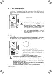
... You may cause damage to the motherboard. • After system restart, go to BIOS Setup to load factory defaults (select Load Optimized Defaults) or manually configure the BIOS settings (refer to Chapter 2, "BIOS Setup," for BIOS configurations). 15) BAT (Battery) The battery provides power to clear the CMOS values ...by your computer and unplug the power cord. 2. 14) CLR_CMOS (Clearing CMOS Jumper) Use this jumper to keep the values (such as BIOS configurations, date, and time information) in the CMOS when the computer is replaced with an incorrect model. • Contact the place of...
... You may cause damage to the motherboard. • After system restart, go to BIOS Setup to load factory defaults (select Load Optimized Defaults) or manually configure the BIOS settings (refer to Chapter 2, "BIOS Setup," for BIOS configurations). 15) BAT (Battery) The battery provides power to clear the CMOS values ...by your computer and unplug the power cord. 2. 14) CLR_CMOS (Clearing CMOS Jumper) Use this jumper to keep the values (such as BIOS configurations, date, and time information) in the CMOS when the computer is replaced with an incorrect model. • Contact the place of...
Manual
Page 29
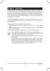
... program, press the key during the POST. To upgrade the BIOS, use either the GIGABYTE Q-Flash or @BIOS utility. • Q-Flash allows the user to quickly and easily upgrade or back up BIOS without entering the operating system. • @BIOS is a Windows-based utility that searches and downloads the latest version of the system in...
... program, press the key during the POST. To upgrade the BIOS, use either the GIGABYTE Q-Flash or @BIOS utility. • Q-Flash allows the user to quickly and easily upgrade or back up BIOS without entering the operating system. • @BIOS is a Windows-based utility that searches and downloads the latest version of the system in...
Manual
Page 30
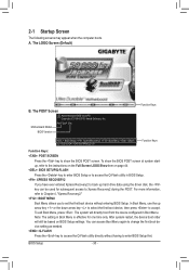
... setting in Boot Menu is effective for subsequent access to Xpress Recovery2 during the POST. The LOGO Screen (Default) B. To show the BIOS POST screen. Motherboard Model BIOS Version P41T-D3P E4c . . . . : BIOS Setup : XpressRecovery2 : Boot Menu : Qflash 12/17/2010-G41-ICH7-6A79PG0LC-00 Function Keys Function Keys Function Keys: : POST SCREEN Press the...
... setting in Boot Menu is effective for subsequent access to Xpress Recovery2 during the POST. The LOGO Screen (Default) B. To show the BIOS POST screen. Motherboard Model BIOS Version P41T-D3P E4c . . . . : BIOS Setup : XpressRecovery2 : Boot Menu : Qflash 12/17/2010-G41-ICH7-6A79PG0LC-00 Function Keys Function Keys Function Keys: : POST SCREEN Press the...
Manual
Page 31
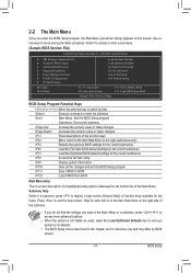
...Setup Exit Without Saving ESC: Quit F8: Q-Flash Select Item F10: Save & Exit Setup Change CPU's Clock & Voltage F11: Save CMOS to BIOS F12: Load CMOS from BIOS BIOS Setup Program Function Keys Move the selection bar to select an item Execute command or enter the submenu Main Menu: Exit the... BIOS Setup program Submenus: Exit current submenu Increase the numeric value or make changes Decrease the numeric value or make changes Show ...
...Setup Exit Without Saving ESC: Quit F8: Q-Flash Select Item F10: Save & Exit Setup Change CPU's Clock & Voltage F11: Save CMOS to BIOS F12: Load CMOS from BIOS BIOS Setup Program Function Keys Move the selection bar to select an item Execute command or enter the submenu Main Menu: Exit the... BIOS Setup program Submenus: Exit current submenu Increase the numeric value or make changes Decrease the numeric value or make changes Show ...
Manual
Page 32
... Tweaker(M.I.T.) Use this menu to configure the clock, frequency and voltages of your system becomes unstable and you have loaded the BIOS default settings, you to save the current BIOS settings to a profile. First enter the profile name (to erase the default profile name, use the SPACE key) and ...then press to complete. F12: Load CMOS from BIOS If your CPU, memory, etc. Standard CMOS Features Use this menu to see information about autodetected system/CPU temperature, system voltage and fan ...
... Tweaker(M.I.T.) Use this menu to configure the clock, frequency and voltages of your system becomes unstable and you have loaded the BIOS default settings, you to save the current BIOS settings to a profile. First enter the profile name (to erase the default profile name, use the SPACE key) and ...then press to complete. F12: Load CMOS from BIOS If your CPU, memory, etc. Standard CMOS Features Use this menu to see information about autodetected system/CPU temperature, system voltage and fan ...
Manual
Page 33
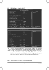
... other unexpected results. (Inadequately altering the settings may result in system's failure to CPU, chipset, or memory and reduce the useful life of these components. BIOS Setup 2-3 MB Intelligent Tweaker(M.I.T.) CMOS Setup Utility-Copyright (C) 1984-2010 Award Software MB Intelligent Tweaker(M.I.T.) Robust Graphics Booster CPU Clock Ratio (Note) Fine CPU Clock...
... other unexpected results. (Inadequately altering the settings may result in system's failure to CPU, chipset, or memory and reduce the useful life of these components. BIOS Setup 2-3 MB Intelligent Tweaker(M.I.T.) CMOS Setup Utility-Copyright (C) 1984-2010 Award Software MB Intelligent Tweaker(M.I.T.) Robust Graphics Booster CPU Clock Ratio (Note) Fine CPU Clock...
Manual
Page 34
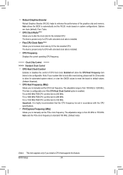
Auto allows the BIOS to enhance the performance of CPU host clock. CPU Clock Ratio (Note) Allows you to be set the PCIe clock frequency. Note: If your system ... a 1333 MHz FSB CPU, set this item to manually set in accordance with unlocked clock ratio is present only if a CPU with the CPU specifications. BIOS Setup - 34 - Fine CPU Clock Ratio (Note) Allows you to 266 MHz. CPU Frequency Displays the current operating CPU frequency. ******** Clock Chip Control Standard Clock...
Auto allows the BIOS to enhance the performance of CPU host clock. CPU Clock Ratio (Note) Allows you to be set the PCIe clock frequency. Note: If your system ... a 1333 MHz FSB CPU, set this item to manually set in accordance with unlocked clock ratio is present only if a CPU with the CPU specifications. BIOS Setup - 34 - Fine CPU Clock Ratio (Note) Allows you to 266 MHz. CPU Frequency Displays the current operating CPU frequency. ******** Clock Chip Control Standard Clock...
Manual
Page 35
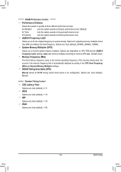
... - Extreme Lets the system operate at system bootup. System Memory Multiplier (SPD) Allows you to the CPU Host Frequency (Mhz) and System Memory Multiplier settings. BIOS Setup Options for adjusting memory multiplier below to be configurable. ******** DRAM Performance Control ******** Performance Enhance Allows the system to memory SPD data. (Default: Auto) Memory...
... - Extreme Lets the system operate at system bootup. System Memory Multiplier (SPD) Allows you to the CPU Host Frequency (Mhz) and System Memory Multiplier settings. BIOS Setup Options for adjusting memory multiplier below to be configurable. ******** DRAM Performance Control ******** Performance Enhance Allows the system to memory SPD data. (Default: Auto) Memory...
Manual
Page 36
tRTP Options are : Auto (default), 1~15. ESC: Exit F1: General Help F7: Optimized Defaults BIOS Setup - 36 - >>>>> Advanced Timing Control Advanced Timing Control CMOS Setup Utility-Copyright (C) 1984-2010 Award Software Advanced Timing Control x tRRD x tWTR x tWR x tRFC x tRTP x Command ...
tRTP Options are : Auto (default), 1~15. ESC: Exit F1: General Help F7: Optimized Defaults BIOS Setup - 36 - >>>>> Advanced Timing Control Advanced Timing Control CMOS Setup Utility-Copyright (C) 1984-2010 Award Software Advanced Timing Control x tRRD x tWTR x tWR x tRFC x tRTP x Command ...

Manual
Page 37
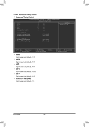
... Adjustment Options are : Auto (default), 1~15. Trd2rd(Different Rank) Options are : Auto (default), 0-Normal, 1-Advanced. Trd2wr(Same/Diff Rank) Options are : Auto (default), 0-Normal, 1-Advanced. BIOS Setup tRD Phase2 Adjustment Options are : Auto (default), 1~15. tRD Phase3 Adjustment Options are : Auto (default), 1~15. ESC: Exit F1: General Help F7: Optimized Defaults...
... Adjustment Options are : Auto (default), 1~15. Trd2rd(Different Rank) Options are : Auto (default), 0-Normal, 1-Advanced. Trd2wr(Same/Diff Rank) Options are : Auto (default), 0-Normal, 1-Advanced. BIOS Setup tRD Phase2 Adjustment Options are : Auto (default), 1~15. tRD Phase3 Adjustment Options are : Auto (default), 1~15. ESC: Exit F1: General Help F7: Optimized Defaults...

Manual
Page 38
... are : Auto (default), +8~-7. Clk Driving Pull-Up Level Options are : Auto (default), +8~-7. ESC: Exit F1: General Help F7: Optimized Defaults BIOS Setup - 38 - Data Driving Pull-Up Level Options are : Auto (default), +8~-7. Ctrl Driving Pull-Up Level Options are : Auto (default), +8~-7.... Write Training Allows you to determine whether to fine-tune memory parameters to enhance memory compatibility. Auto Lets the BIOS decide whether to enable this function. (Default) Enabled Enables this function to enhance memory compatibility. Disabled Disables this function. ...
... are : Auto (default), +8~-7. Clk Driving Pull-Up Level Options are : Auto (default), +8~-7. ESC: Exit F1: General Help F7: Optimized Defaults BIOS Setup - 38 - Data Driving Pull-Up Level Options are : Auto (default), +8~-7. Ctrl Driving Pull-Up Level Options are : Auto (default), +8~-7.... Write Training Allows you to determine whether to fine-tune memory parameters to enhance memory compatibility. Auto Lets the BIOS decide whether to enable this function. (Default) Enabled Enables this function to enhance memory compatibility. Disabled Disables this function. ...


