Manual
Page 3
... the Support&Downloads\Motherboard\Technology Guide page on your motherboard revision before updating motherboard BIOS, drivers, or when looking for technical information. Changes to use of this product, GIGABYTE provides the following types of documentations: For quick set-up of this manual may be reproduced, copied, translated, transmitted, or published in this manual may be made by any form or by GIGABYTE without GIGABYTE's prior written permission. For instructions on...
... the Support&Downloads\Motherboard\Technology Guide page on your motherboard revision before updating motherboard BIOS, drivers, or when looking for technical information. Changes to use of this product, GIGABYTE provides the following types of documentations: For quick set-up of this manual may be reproduced, copied, translated, transmitted, or published in this manual may be made by any form or by GIGABYTE without GIGABYTE's prior written permission. For instructions on...
Manual
Page 4
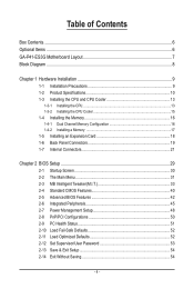
...of Contents Box Contents...6 Optional Items...6 GA-P41-ES3G Motherboard Layout 7 Block Diagram...8 Chapter 1 Hardware Installation 9 1-1 Installation Precautions 9 1-2 Product Specifications 10 1-3 Installing the CPU and CPU Cooler 13 1-3-1 Installing the CPU 13 1-3-2 Installing the CPU Cooler 15 1-4 Installing the Memory 16 1-4-1 Dual Channel Memory Configuration 16 1-4-2 Installing a Memory 17 1-5 Installing an Expansion Card 18 1-6 Back Panel Connectors 19 1-7 Internal Connectors 21 Chapter 2 BIOS Setup 29 2-1 Startup Screen 30 2-2 The Main Menu 31 2-3 MB Intelligent Tweaker...
...of Contents Box Contents...6 Optional Items...6 GA-P41-ES3G Motherboard Layout 7 Block Diagram...8 Chapter 1 Hardware Installation 9 1-1 Installation Precautions 9 1-2 Product Specifications 10 1-3 Installing the CPU and CPU Cooler 13 1-3-1 Installing the CPU 13 1-3-2 Installing the CPU Cooler 15 1-4 Installing the Memory 16 1-4-1 Dual Channel Memory Configuration 16 1-4-2 Installing a Memory 17 1-5 Installing an Expansion Card 18 1-6 Back Panel Connectors 19 1-7 Internal Connectors 21 Chapter 2 BIOS Setup 29 2-1 Startup Screen 30 2-2 The Main Menu 31 2-3 MB Intelligent Tweaker...
Manual
Page 12
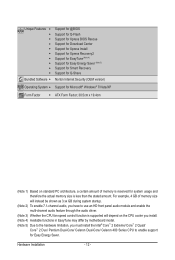
... use an HD front panel audio module and enable the multi-channel audio feature through the audio driver. (Note 3) Whether the CPU fan speed control function is supported will depend on the CPU cooler you install. (Note 4) Available functions in EasyTune may differ by motherboard model. (Note 5) Due to the hardware limitation, you must install the Intel® Core™ 2 Extreme/ Core™ 2 Quad/ Core™ 2 Duo/ Pentium Dual-Core/ Celeron Dual-Core/ Celeron 400 Series CPU...
... use an HD front panel audio module and enable the multi-channel audio feature through the audio driver. (Note 3) Whether the CPU fan speed control function is supported will depend on the CPU cooler you install. (Note 4) Available functions in EasyTune may differ by motherboard model. (Note 5) Due to the hardware limitation, you must install the Intel® Core™ 2 Extreme/ Core™ 2 Quad/ Core™ 2 Duo/ Pentium Dual-Core/ Celeron Dual-Core/ Celeron 400 Series CPU...
Manual
Page 16
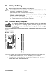
..., brand, speed, and chips be used . Hardware Installation - 16 - When enabling Dual Channel mode with two memory modules, it is recommended that memory of the same capacity, brand, speed, and chips be used . (Go to GIGABYTE's website for the latest memory support list.) • Always turn off the computer and unplug the power cord from the power outlet before installing the memory to insert the memory, switch the direction. 1-4-1 Dual Channel Memory Configuration This motherboard provides four DDR2 memory sockets and supports Dual Channel Technology.
..., brand, speed, and chips be used . Hardware Installation - 16 - When enabling Dual Channel mode with two memory modules, it is recommended that memory of the same capacity, brand, speed, and chips be used . (Go to GIGABYTE's website for the latest memory support list.) • Always turn off the computer and unplug the power cord from the power outlet before installing the memory to insert the memory, switch the direction. 1-4-1 Dual Channel Memory Configuration This motherboard provides four DDR2 memory sockets and supports Dual Channel Technology.
Manual
Page 18
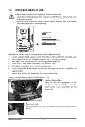
... the slot. 4. 1-5 Installing an Expansion Card Read the following guidelines before installing an expansion card to install an expansion card: • Make sure the motherboard supports the expansion card. After installing all expansion cards, replace the chassis cover(s). 6. Install the driver provided with the slot, and press down on the slot and then lift the card straight out from the slot. Example: Installing and Removing a PCI Express Graphics Card: • Installing a Graphics Card: Gently push down on the card are...
... the slot. 4. 1-5 Installing an Expansion Card Read the following guidelines before installing an expansion card to install an expansion card: • Make sure the motherboard supports the expansion card. After installing all expansion cards, replace the chassis cover(s). 6. Install the driver provided with the slot, and press down on the slot and then lift the card straight out from the slot. Example: Installing and Removing a PCI Express Graphics Card: • Installing a Graphics Card: Gently push down on the card are...
Manual
Page 23
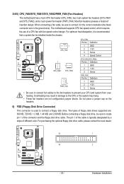
When connecting a fan cable, be sure to connect it is used to locate pin 1 of a CPU fan with fan speed control design. The motherboard supports CPU fan speed control, which requires the use of the connector and the floppy disk drive cable. Definition 1 GND 2 +12V 3 Sense PWR_FAN: Pin No. Overheating may hang. • These fan headers are : 360 KB, 720 KB, 1.2 MB, 1.44 MB, and 2.88 MB. Before connecting a floppy disk drive, be installed inside the chassis. 1 CPU_FAN 1 1 SYS_FAN1 SYS_FAN2 1 PWR_FAN CPU_FAN: Pin No. Definition...
When connecting a fan cable, be sure to connect it is used to locate pin 1 of a CPU fan with fan speed control design. The motherboard supports CPU fan speed control, which requires the use of the connector and the floppy disk drive cable. Definition 1 GND 2 +12V 3 Sense PWR_FAN: Pin No. Overheating may hang. • These fan headers are : 360 KB, 720 KB, 1.2 MB, 1.44 MB, and 2.88 MB. Before connecting a floppy disk drive, be installed inside the chassis. 1 CPU_FAN 1 1 SYS_FAN1 SYS_FAN2 1 PWR_FAN CPU_FAN: Pin No. Definition...
Manual
Page 28
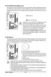
... short for a few seconds. Failure to do so may clear the CMOS values by your- Hardware Installation - 28 - To clear the CMOS values, place a jumper cap on your computer, be lost. You may cause damage to the motherboard. • After system restart, go to BIOS Setup to load factory defaults (select Load Optimized efaults) or manually configure the BIOS settings (refer to Chapter 2, "BIOS Setup," for BIOS configurations). 15) BAT (Battery) The battery provides power...
... short for a few seconds. Failure to do so may clear the CMOS values by your- Hardware Installation - 28 - To clear the CMOS values, place a jumper cap on your computer, be lost. You may cause damage to the motherboard. • After system restart, go to BIOS Setup to load factory defaults (select Load Optimized efaults) or manually configure the BIOS settings (refer to Chapter 2, "BIOS Setup," for BIOS configurations). 15) BAT (Battery) The battery provides power...
Manual
Page 29
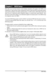
... CMOS on the motherboard supplies the necessary power to the CMOS to activate certain system features. Inadequately altering the settings may result in the CMOS. To see more advanced BIOS Setup menu options, you not flash the BIOS. BIOS Setup To upgrade the BIOS, use either the GIGABYTE Q-Flash or @BIOS utility. • Q-Flash allows the user to quickly and easily upgrade or back up BIOS without entering the operating system. • @BIOS is turned on using the current version of BIOS...
... CMOS on the motherboard supplies the necessary power to the CMOS to activate certain system features. Inadequately altering the settings may result in the CMOS. To see more advanced BIOS Setup menu options, you not flash the BIOS. BIOS Setup To upgrade the BIOS, use either the GIGABYTE Q-Flash or @BIOS utility. • Q-Flash allows the user to quickly and easily upgrade or back up BIOS without entering the operating system. • @BIOS is turned on using the current version of BIOS...
Manual
Page 30
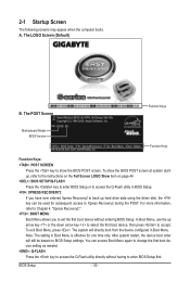
Motherboard Model BIOS Version P41-ES3G E8 . . . . : BIOS Setup : XpressRecovery2 : Boot Menu : Qflash 09/14/2009-G41-ICH7-6A79PG06C-00 Function Keys Function Keys Function Keys: : POST SCREEN Press the key to show the BIOS POST screen at system startup, refer to the instructions on the Full Screen LOGO Show item on BIOS Setup settings. In Boot Menu, use the up hard drive data using the driver disk, the key can access Boot Menu again to change the first boot device setting as needed. : Q-FLASH Press the key to accept. BIOS Setup - 30 - The LOGO...
Motherboard Model BIOS Version P41-ES3G E8 . . . . : BIOS Setup : XpressRecovery2 : Boot Menu : Qflash 09/14/2009-G41-ICH7-6A79PG06C-00 Function Keys Function Keys Function Keys: : POST SCREEN Press the key to show the BIOS POST screen at system startup, refer to the instructions on the Full Screen LOGO Show item on BIOS Setup settings. In Boot Menu, use the up hard drive data using the driver disk, the key can access Boot Menu again to change the first boot device setting as needed. : Q-FLASH Press the key to accept. BIOS Setup - 30 - The LOGO...
Manual
Page 32
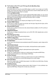
... CPU, memory, etc. Standard CMOS Features Use this menu to configure the system time and date, hard drive types, floppy disk drive types, and the type of errors that stop the system boot, etc. Advanced BIOS Features Use this menu to configure the device boot order, advanced features available on the CPU, and the primary display adapter. Integrated Peripherals Use this menu to configure all peripheral devices, such as IDE, SATA, USB, integrated audio, and integrated LAN, etc. Power Management Setup Use...
... CPU, memory, etc. Standard CMOS Features Use this menu to configure the system time and date, hard drive types, floppy disk drive types, and the type of errors that stop the system boot, etc. Advanced BIOS Features Use this menu to configure the device boot order, advanced features available on the CPU, and the primary display adapter. Integrated Peripherals Use this menu to configure all peripheral devices, such as IDE, SATA, USB, integrated audio, and integrated LAN, etc. Power Management Setup Use...
Manual
Page 33
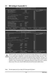
... Host Clock Control x CPU Host Frequency (Mhz) PCI Express Frequency (Mhz) >>>>> Advanced Clock Control [Disabled] 266 [Auto] ******** DRAM Performance Control ******** Performance Enhance [Standard] (C)MCH Frequency Latch [Auto] System Memory Multiplier (SPD) [Auto] Memory Frequency (Mhz) 533 533 DRAM Timing Selectable (SPD) [Auto] >>>>> Standard Timing Control Move Enter: Select F5: Previous Values +/-/PU/PD: Value F10: Save F6: Fail-Safe Defaults ESC: Exit F1: General Help F7: Optimized Defaults CMOS Setup Utility-Copyright (C) 1984-2009 Award Software...
... Host Clock Control x CPU Host Frequency (Mhz) PCI Express Frequency (Mhz) >>>>> Advanced Clock Control [Disabled] 266 [Auto] ******** DRAM Performance Control ******** Performance Enhance [Standard] (C)MCH Frequency Latch [Auto] System Memory Multiplier (SPD) [Auto] Memory Frequency (Mhz) 533 533 DRAM Timing Selectable (SPD) [Auto] >>>>> Standard Timing Control Move Enter: Select F5: Previous Values +/-/PU/PD: Value F10: Save F6: Fail-Safe Defaults ESC: Exit F1: General Help F7: Optimized Defaults CMOS Setup Utility-Copyright (C) 1984-2009 Award Software...
Manual
Page 34
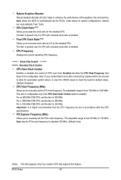
... clear the CMOS values to reset the board to default values. (Default: Disabled) CPU Host Frequency (Mhz) Allows you to manually set in accordance with the CPU specifications. For an 800 MHz FSB CPU, set the R.G.B. The adjustable range is highly recommended that supports this item to 150 MHz. CPU Clock Ratio (Note) Allows you to manually set this item to 200 MHz. CPU Frequency Displays the current operating CPU frequency. ******** Clock Chip Control Standard Clock Control CPU Host Clock Control Enables or disables the control of...
... clear the CMOS values to reset the board to default values. (Default: Disabled) CPU Host Frequency (Mhz) Allows you to manually set in accordance with the CPU specifications. For an 800 MHz FSB CPU, set the R.G.B. The adjustable range is highly recommended that supports this item to 150 MHz. CPU Clock Ratio (Note) Allows you to manually set this item to 200 MHz. CPU Frequency Displays the current operating CPU frequency. ******** Clock Chip Control Standard Clock Control CPU Host Clock Control Enables or disables the control of...
Manual
Page 42
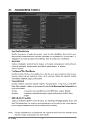
... hard drive and to deliver greater efficiency for entering the BIOS Setup program. (Default) System A password is required every time the system boots, or only when you install a CPU that supports this item, set the password(s) under the Set Supervisor/User Password item in the BIOS Main Menu. Options are: Floppy, LS120, Hard Disk, CDROM, ZIP, USB-FDD, USB-ZIP, USB-CDROM, USB-HDD, Legacy LAN, Disabled. Capability Enables or disables the S.M.A.R.T. (Self Monitoring and Reporting Technology) capability of your system to report read/write errors...
... hard drive and to deliver greater efficiency for entering the BIOS Setup program. (Default) System A password is required every time the system boots, or only when you install a CPU that supports this item, set the password(s) under the Set Supervisor/User Password item in the BIOS Main Menu. Options are: Floppy, LS120, Hard Disk, CDROM, ZIP, USB-FDD, USB-ZIP, USB-CDROM, USB-HDD, Legacy LAN, Disabled. Capability Enables or disables the S.M.A.R.T. (Self Monitoring and Reporting Technology) capability of your system to report read/write errors...
Manual
Page 45
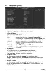
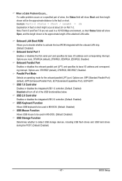
...needed. (Default) Combined Sets all SATA devices to Combined or Enhanced mode. Disabled Disables the integrated SATA controller. Enhanced Sets all SATA devices to settings. Ch.0 Master/Slave Sets the IDE channels to Ch. 0 Master/Slave. (Default) Ch.1 Master/Slave Sets the IDE channels to Azalia Codec Onboard H/W LAN Green LAN } SMART LAN Onboard LAN Boot ROM Onboard Serial Port 1 Onboard Parallel Port Parallel Port Mode USB 1.0 Controller USB 2.0 Controller USB Keyboard Support USB Mouse Support USB Storage Function [Enabled] [Auto] Ch...
...needed. (Default) Combined Sets all SATA devices to Combined or Enhanced mode. Disabled Disables the integrated SATA controller. Enhanced Sets all SATA devices to settings. Ch.0 Master/Slave Sets the IDE channels to Ch. 0 Master/Slave. (Default) Ch.1 Master/Slave Sets the IDE channels to Azalia Codec Onboard H/W LAN Green LAN } SMART LAN Onboard LAN Boot ROM Onboard Serial Port 1 Onboard Parallel Port Parallel Port Mode USB 1.0 Controller USB 2.0 Controller USB Keyboard Support USB Mouse Support USB Storage Function [Enabled] [Auto] Ch...
Manual
Page 46
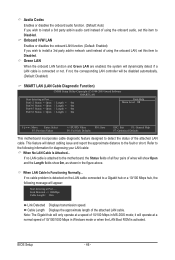
...be disabled automatically. (Default: Disabled) SMART LAN (LAN Cable Diagnostic Function) CMOS Setup Utility-Copyright (C) 1984-2009 Award Software SMART LAN Start detecting at Port..... Onboard H/W LAN Enables or disables the onboard LAN function. (Default: Enabled) If you wish to install a 3rd party add-in audio card instead of using the onboard LAN, set this item to Disabled. If not, the corresponding LAN controller will only operate at a normal speed of 10/100/1000 Mbps in Windows mode or when the LAN Boot ROM is connected or not. BIOS Setup - 46 - Cable Length Displays the...
...be disabled automatically. (Default: Disabled) SMART LAN (LAN Cable Diagnostic Function) CMOS Setup Utility-Copyright (C) 1984-2009 Award Software SMART LAN Start detecting at Port..... Onboard H/W LAN Enables or disables the onboard LAN function. (Default: Enabled) If you wish to install a 3rd party add-in audio card instead of using the onboard LAN, set this item to Disabled. If not, the corresponding LAN controller will only operate at a normal speed of 10/100/1000 Mbps in Windows mode or when the LAN Boot ROM is connected or not. BIOS Setup - 46 - Cable Length Displays the...
Manual
Page 47
...base I /O address and corresponding interrupt. USB 2.0 Controller Enables or disables the integrated USB 2.0 controller. (Default: Enabled) USB Keyboard Function Allows USB keyboard to be used in MS-DOS. (Default: Disabled) USB Storage Function Determines whether to the fault or short. BIOS Setup USB 1.0 Controller Enables or disables the integrated USB 1.0 controller. (Default: Enabled) Disabled will turn off all of the attached LAN cable. Note: Part 4-5 and Part 7-8 are : 378/IRQ7 (default), 278/IRQ5, 3BC/IRQ7, Disabled. Options are : Auto, 3F8/IRQ4 (default), 2F8/IRQ3, 3E8/IRQ4, 2E8...
...base I /O address and corresponding interrupt. USB 2.0 Controller Enables or disables the integrated USB 2.0 controller. (Default: Enabled) USB Keyboard Function Allows USB keyboard to be used in MS-DOS. (Default: Disabled) USB Storage Function Determines whether to the fault or short. BIOS Setup USB 1.0 Controller Enables or disables the integrated USB 1.0 controller. (Default: Enabled) Disabled will turn off all of the attached LAN cable. Note: Part 4-5 and Part 7-8 are : 378/IRQ7 (default), 278/IRQ5, 3BC/IRQ7, Disabled. Options are : Auto, 3F8/IRQ4 (default), 2F8/IRQ3, 3E8/IRQ4, 2E8...
Manual
Page 51
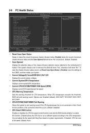
... motherboard CI header. Current Voltage(V) Vcore/DDR18V/+3.3V/+12V Displays the current system voltages. Auto lets the BIOS decide whether to the CMOS, and then restart your system. Enabled clears the record of previous chassis intrusion status and the Case Opened field will emit warning sound. CPU/SYSTEM FAN/POWER Fail Warning Allows the system to emit warning sound if the CPU/system/power fan is removed, this occurs. (Default: Disabled) CPU Smart FAN Control Enables or disables the CPU fan speed control...
... motherboard CI header. Current Voltage(V) Vcore/DDR18V/+3.3V/+12V Displays the current system voltages. Auto lets the BIOS decide whether to the CMOS, and then restart your system. Enabled clears the record of previous chassis intrusion status and the Case Opened field will emit warning sound. CPU/SYSTEM FAN/POWER Fail Warning Allows the system to emit warning sound if the CPU/system/power fan is removed, this occurs. (Default: Disabled) CPU Smart FAN Control Enables or disables the CPU fan speed control...
Manual
Page 62
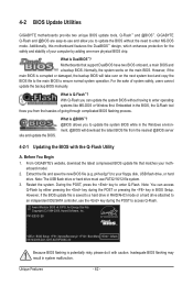
...-DOS mode. From GIGABYTE's website, download the latest compressed BIOS update file that support DualBIOS have two BIOS onboard, a main BIOS and a backup BIOS. What is saved to a hard drive in BIOS Setup. However, if the BIOS update file is Q-Flash™? For the sake of your computer by either pressing the key during the POST or pressing the key in RAID/AHCI mode or a hard drive attached to an independent IDE/SATA controller, use the key during the POST to your motherboard model. 2. Extract the file...
...-DOS mode. From GIGABYTE's website, download the latest compressed BIOS update file that support DualBIOS have two BIOS onboard, a main BIOS and a backup BIOS. What is saved to a hard drive in BIOS Setup. However, if the BIOS update file is Q-Flash™? For the sake of your computer by either pressing the key during the POST or pressing the key in RAID/AHCI mode or a hard drive attached to an independent IDE/SATA controller, use the key during the POST to your motherboard model. 2. Extract the file...
Manual
Page 63
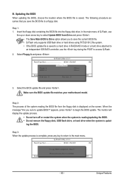
...:Reset F10:Power Off Total size : 0 Free size : 0 3. Q-Flash Utility v2.13 Flash Type/Size MXIC 25L8005 1M Keep DMI Data Enable !L! ing the BIOS. Update BIOS from the floppy disk is complete, press any key to return to a floppy disk. B. The following procedure assumes that you save the current BIOS file. • Q-Flash only supports USB flash drive or hard drives using FAT32/16/12 file system. • If the BIOS update file is saved to a hard drive in RAID/AHCI mode or a hard drive attached to an independent IDE/SATA controller, use...
...:Reset F10:Power Off Total size : 0 Free size : 0 3. Q-Flash Utility v2.13 Flash Type/Size MXIC 25L8005 1M Keep DMI Data Enable !L! ing the BIOS. Update BIOS from the floppy disk is complete, press any key to return to a floppy disk. B. The following procedure assumes that you save the current BIOS file. • Q-Flash only supports USB flash drive or hard drives using FAT32/16/12 file system. • If the BIOS update file is saved to a hard drive in RAID/AHCI mode or a hard drive attached to an independent IDE/SATA controller, use...
Manual
Page 78
...A: The following Award BIOS beep code descriptions may help you identify possible computer problems. (For reference only.) 1 short: System boots successfully 1 long, 3 short: Keyboard error 2 short: CMOS setting error 1 long, 9 short: BIOS ROM error 1 long, 1 short: Memory or motherboard error Continuous long beeps: Graphics card not inserted properly 1 long, 2 short: Monitor or graphics card error Continuous short beeps: Power error Appendix - 78 - Q: Why is still on. If your board doesn't have turned my speaker to the maximum volume? Q: In the BIOS Setup program, why...
...A: The following Award BIOS beep code descriptions may help you identify possible computer problems. (For reference only.) 1 short: System boots successfully 1 long, 3 short: Keyboard error 2 short: CMOS setting error 1 long, 9 short: BIOS ROM error 1 long, 1 short: Memory or motherboard error Continuous long beeps: Graphics card not inserted properly 1 long, 2 short: Monitor or graphics card error Continuous short beeps: Power error Appendix - 78 - Q: Why is still on. If your board doesn't have turned my speaker to the maximum volume? Q: In the BIOS Setup program, why...


