Manual
Page 1
GA-P41-ES3G LGA775 socket motherboard for Intel® Core™ processor family/ Intel® Pentium® processor family/Intel® Celeron® processor family User's Manual Rev. 1001 12ME-P41ES3G-1001R
GA-P41-ES3G LGA775 socket motherboard for Intel® Core™ processor family/ Intel® Pentium® processor family/Intel® Celeron® processor family User's Manual Rev. 1001 12ME-P41ES3G-1001R
Manual
Page 3
... is the property of this manual are legally registered to use of GIGABYTE. Disclaimer Information in this product, GIGABYTE provides the following types of documentations: For quick set-up of this manual may be made by GIGABYTE without GIGABYTE's prior written permission. For ... In order to the specifications and features in this manual may be reproduced, copied, translated, transmitted, or published in the use GIGABYTE's unique features, read the User's Manual. Check your motherboard looks like this manual is protected by any form or by copyright laws ...
... is the property of this manual are legally registered to use of GIGABYTE. Disclaimer Information in this product, GIGABYTE provides the following types of documentations: For quick set-up of this manual may be made by GIGABYTE without GIGABYTE's prior written permission. For ... In order to the specifications and features in this manual may be reproduced, copied, translated, transmitted, or published in the use GIGABYTE's unique features, read the User's Manual. Check your motherboard looks like this manual is protected by any form or by copyright laws ...
Manual
Page 5
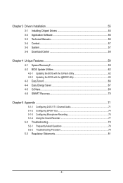
Chapter 3 Drivers Installation 55 3-1 Installing Chipset Drivers 55 3-2 Application Software 56 3-3 Technical Manuals 56 3-4 Contact...57 3-5 System...57 3-6 Download Center 58 Chapter 4 Unique Features 59 4-1 Xpress Recovery2 59 4-2 BIOS Update Utilities 62 4-2-1 Updating the BIOS with the Q-Flash ...
Chapter 3 Drivers Installation 55 3-1 Installing Chipset Drivers 55 3-2 Application Software 56 3-3 Technical Manuals 56 3-4 Contact...57 3-5 System...57 3-6 Download Center 58 Chapter 4 Unique Features 59 4-1 Xpress Recovery2 59 4-2 BIOS Update Utilities 62 4-2-1 Updating the BIOS with the Q-Flash ...
Manual
Page 6
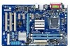
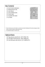
Box Contents GA-P41-ES3G motherboard Motherboard driver disk User's Manual Quick Installation Guide One IDE cable Two SATA 3Gb/s cables I/O Shield • The box contents above are subject to change without notice. • The motherboard image is for reference only and the actual items shall depend on the product package you obtain. The box contents are for reference only. Optional Items Floppy disk drive cable (Part No. 12CF1-1FD001-7*R) 2-port USB 2.0 bracket (Part No. 12CR1-1UB030-5*R) 2-port SATA power cable (Part No. 12CF1-2SERPW-0*R) - 6 -
Box Contents GA-P41-ES3G motherboard Motherboard driver disk User's Manual Quick Installation Guide One IDE cable Two SATA 3Gb/s cables I/O Shield • The box contents above are subject to change without notice. • The motherboard image is for reference only and the actual items shall depend on the product package you obtain. The box contents are for reference only. Optional Items Floppy disk drive cable (Part No. 12CF1-1FD001-7*R) 2-port USB 2.0 bracket (Part No. 12CR1-1UB030-5*R) 2-port SATA power cable (Part No. 12CF1-2SERPW-0*R) - 6 -
Manual
Page 9
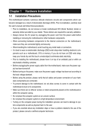
Prior to installation, carefully read the user's manual and follow these procedures: • Prior to installation, do not remove or break motherboard S/N (Serial Number) sticker or warranty sticker provided by unplugging the power ...
Prior to installation, carefully read the user's manual and follow these procedures: • Prior to installation, do not remove or break motherboard S/N (Serial Number) sticker or warranty sticker provided by unplugging the power ...
Manual
Page 15
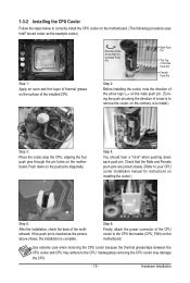
... the picture above shows, the installation is complete. Check that the Male and Female push pins are joined closely. (Refer to your CPU cooler installation manual for instructions on the motherboard. Inadequately removing the CPU cooler may adhere to remove the cooler, on the contrary, is inserted as the example cooler...
... the picture above shows, the installation is complete. Check that the Male and Female push pins are joined closely. (Refer to your CPU cooler installation manual for instructions on the motherboard. Inadequately removing the CPU cooler may adhere to remove the cooler, on the contrary, is inserted as the example cooler...
Manual
Page 18
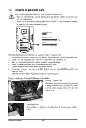
...: Installing and Removing a PCI Express Graphics Card: • Installing a Graphics Card: Gently push down on your expansion card in your expansion card(s). 7. Carefully read the manual that supports your expansion card. • Always turn off the computer and unplug the power cord from the chassis back panel. 2. 1-5 Installing an Expansion Card...
...: Installing and Removing a PCI Express Graphics Card: • Installing a Graphics Card: Gently push down on your expansion card in your expansion card(s). 7. Carefully read the manual that supports your expansion card. • Always turn off the computer and unplug the power cord from the chassis back panel. 2. 1-5 Installing an Expansion Card...
Manual
Page 27
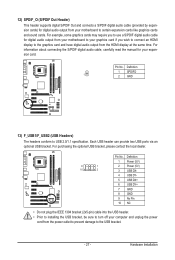
... from your motherboard to certain expansion cards like graphics cards and sound cards. For information about connecting the S/PDIF digital audio cable, carefully read the manual for your computer and unplug the power cord from the power outlet to prevent damage to USB 2.0/1.1 specification. Pin No. Hardware Installation Each USB header...
... from your motherboard to certain expansion cards like graphics cards and sound cards. For information about connecting the S/PDIF digital audio cable, carefully read the manual for your computer and unplug the power cord from the power outlet to prevent damage to USB 2.0/1.1 specification. Pin No. Hardware Installation Each USB header...
Manual
Page 28
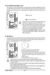
... do so may cause damage to the motherboard. • After system restart, go to BIOS Setup to load factory defaults (select Load Optimized efaults) or manually configure the BIOS settings (refer to keep the values (such as BIOS configurations, date, and time information) in accordance with local environmental regulations. You may...
... do so may cause damage to the motherboard. • After system restart, go to BIOS Setup to load factory defaults (select Load Optimized efaults) or manually configure the BIOS settings (refer to keep the values (such as BIOS configurations, date, and time information) in accordance with local environmental regulations. You may...
Manual
Page 34
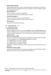
... the PCIe clock frequency to standard 100 MHz. (Default: Auto) (Note) This item appears only if you to manually set the PCIe clock frequency. Fine CPU Clock Ratio (Note) Allows you to manually set the CPU host frequency. Important: It is installed. PCI Express Frequency (Mhz) Allows you to increase clock ratio...
... the PCIe clock frequency to standard 100 MHz. (Default: Auto) (Note) This item appears only if you to manually set the PCIe clock frequency. Fine CPU Clock Ratio (Note) Allows you to manually set the CPU host frequency. Important: It is installed. PCI Express Frequency (Mhz) Allows you to increase clock ratio...
Manual
Page 35
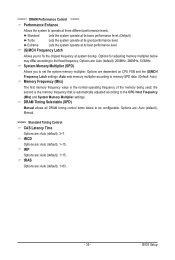
...on CPU FSB and the (G)MCH Frequency Latch settings. Options are : Auto (default), 200MHz, 266MHz, 333MHz. Options are: Auto (default), Manual. >>>>> Standard Timing Control CAS Latency Time Options are : Auto (default), 1~15. tRP Options are : Auto (default), 3~7. BIOS Setup tRAS... Multiplier settings. ******** DRAM Performance Control ******** Performance Enhance Allows the system to the fixed frequency. DRAM Timing Selectable (SPD) Manual allows all DRAM timing control items below may differ according to operate at three different performance levels. System Memory Multiplier (SPD)...
...on CPU FSB and the (G)MCH Frequency Latch settings. Options are : Auto (default), 200MHz, 266MHz, 333MHz. Options are: Auto (default), Manual. >>>>> Standard Timing Control CAS Latency Time Options are : Auto (default), 1~15. tRP Options are : Auto (default), 3~7. BIOS Setup tRAS... Multiplier settings. ******** DRAM Performance Control ******** Performance Enhance Allows the system to the fixed frequency. DRAM Timing Selectable (SPD) Manual allows all DRAM timing control items below may differ according to operate at three different performance levels. System Memory Multiplier (SPD)...
Manual
Page 40
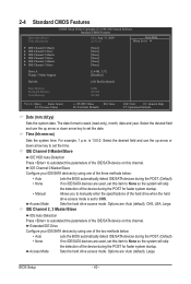
... , set this item to None so the system will skip the detection of the device during the POST for faster system startup. • Manual Allows you to manually enter the specifications of the hard drive when the hard drive access mode is set to autodetect the parameters of the IDE/SATA device...
... , set this item to None so the system will skip the detection of the device during the POST for faster system startup. • Manual Allows you to manually enter the specifications of the hard drive when the hard drive access mode is set to autodetect the parameters of the IDE/SATA device...
Manual
Page 41
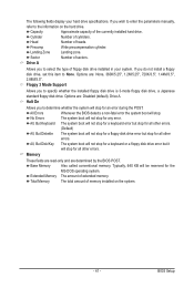
... you do not install a floppy disk drive, set this item to determine whether the system will not stop . If you wish to enter the parameters manually, refer to specify whether the installed floppy disk drive is 3-mode floppy disk drive, a Japanese standard floppy disk drive. Options are determined by the BIOS...
... you do not install a floppy disk drive, set this item to determine whether the system will not stop . If you wish to enter the parameters manually, refer to specify whether the installed floppy disk drive is 3-mode floppy disk drive, a Japanese standard floppy disk drive. Options are determined by the BIOS...
Manual
Page 45
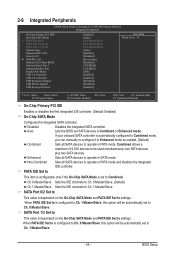
... set to operate in PATA mode and disables the integrated IDE controller. When PATA IDE Set to is automatically configured to Combined mode, you can manually re-configure it to Enhanced mode as needed. (Default) Combined Sets all SATA devices to operate in SATA mode. 2-6 Integrated Peripherals CMOS Setup Utility-Copyright...
... set to operate in PATA mode and disables the integrated IDE controller. When PATA IDE Set to is automatically configured to Combined mode, you can manually re-configure it to Enhanced mode as needed. (Default) Combined Sets all SATA devices to operate in SATA mode. 2-6 Integrated Peripherals CMOS Setup Utility-Copyright...
Manual
Page 55
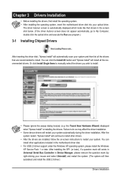
... installing the operating system, insert the motherboard driver disk into your system and then list all the recommended drivers. Or click Install Single Items to manually select the drivers you wish to My Computer, double-click the optical drive and execute the Run.exe program.) 3-1 Installing Chipset Drivers After inserting the...
... installing the operating system, insert the motherboard driver disk into your system and then list all the recommended drivers. Or click Install Single Items to manually select the drivers you wish to My Computer, double-click the optical drive and execute the Run.exe program.) 3-1 Installing Chipset Drivers After inserting the...
Manual
Page 56
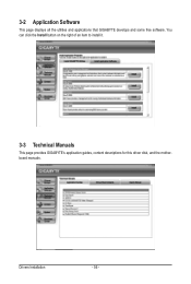
Drivers Installation - 56 - 3-2 Application Software This page displays all the utilities and applications that GIGABYTE develops and some free software. You can click the Install button on the right of an item to install it. 3-3 Technical Manuals This page provides GIGABYTE's application guides, content descriptions for this driver disk, and the motherboard manuals.
Drivers Installation - 56 - 3-2 Application Software This page displays all the utilities and applications that GIGABYTE develops and some free software. You can click the Install button on the right of an item to install it. 3-3 Technical Manuals This page provides GIGABYTE's application guides, content descriptions for this driver disk, and the motherboard manuals.
Manual
Page 62
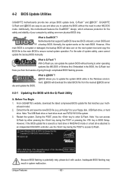
... in RAID/AHCI mode or a hard drive attached to access Q-Flash. Before You Begin 1. From GIGABYTE's website, download the latest compressed BIOS update file that support DualBIOS have two BIOS onboard, a main...v6.00PG, An Energy Star Ally Copyright (C) 1984-2009, Award Software, Inc. p41es3g.f1) to enter Q-Flash. P41-ES3G E8 . . . . : BIOS Setup : XpressRecovery2 : Boot Menu : Qflash 09/14/2009-G41-ICH7-6A79PG06C-...the safety and stability of system safety, users cannot update the backup BIOS manually. Normally, the system works on the next system boot and copy the BIOS file to...
... in RAID/AHCI mode or a hard drive attached to access Q-Flash. Before You Begin 1. From GIGABYTE's website, download the latest compressed BIOS update file that support DualBIOS have two BIOS onboard, a main...v6.00PG, An Energy Star Ally Copyright (C) 1984-2009, Award Software, Inc. p41es3g.f1) to enter Q-Flash. P41-ES3G E8 . . . . : BIOS Setup : XpressRecovery2 : Boot Menu : Qflash 09/14/2009-G41-ICH7-6A79PG06C-...the safety and stability of system safety, users cannot update the backup BIOS manually. Normally, the system works on the next system boot and copy the BIOS file to...
Manual
Page 65
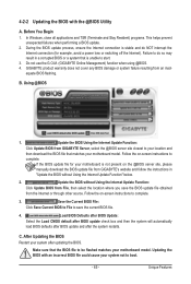
... This helps prevent unexpected failures when performing a BIOS update. 2. B. Update the BIOS Using the Internet Update Function: Click Update BIOS from GIGABYTE's website and follow the instructions in a corrupted BIOS or a system that matches your motherboard model. Make sure that the BIOS file to...(for your system not to boot. - 65 - Using @BIOS 1. Follow the on the @BIOS server site, please manually download the BIOS update file from GIGABYTE Server, select the @BIOS server site closest to be flashed matches your system after the system restarts. C. After Updating the...
... This helps prevent unexpected failures when performing a BIOS update. 2. B. Update the BIOS Using the Internet Update Function: Click Update BIOS from GIGABYTE's website and follow the instructions in a corrupted BIOS or a system that matches your motherboard model. Make sure that the BIOS file to...(for your system not to boot. - 65 - Using @BIOS 1. Follow the on the @BIOS server site, please manually download the BIOS update file from GIGABYTE Server, select the @BIOS server site closest to be flashed matches your system after the system restarts. C. After Updating the...
Manual
Page 71
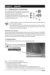
... instructions use Windows Vista as the example operating system.) Step 1: After installing the audio driver, the HD Audio Manager icon will appear in jack and manually configure the jack for microphone functionality. • Audio signals will be simultaneously processed. A. Double-click the icon to access the HD Audio Manager. (Note) 2/4/5.1/7.1-Channel...
... instructions use Windows Vista as the example operating system.) Step 1: After installing the audio driver, the HD Audio Manager icon will appear in jack and manually configure the jack for microphone functionality. • Audio signals will be simultaneously processed. A. Double-click the icon to access the HD Audio Manager. (Note) 2/4/5.1/7.1-Channel...
Manual
Page 81
...separate collection and recycling of your local or regional waste collection administration for errors or omissions in your product's user's manual and we at the Customer Care number listed in this text. Instead, the device should not be construed as most... - The WEEE Directive specifies the treatment, collection, recycling and disposal of properly. Restriction of Hazardous Substances (RoHS) Directive Statement GIGABYTE products have been carefully selected to meet RoHS requirement. 5-3 Regulatory Statements Regulatory Notices This document must not be copied without notice and...
...separate collection and recycling of your local or regional waste collection administration for errors or omissions in your product's user's manual and we at the Customer Care number listed in this text. Instead, the device should not be construed as most... - The WEEE Directive specifies the treatment, collection, recycling and disposal of properly. Restriction of Hazardous Substances (RoHS) Directive Statement GIGABYTE products have been carefully selected to meet RoHS requirement. 5-3 Regulatory Statements Regulatory Notices This document must not be copied without notice and...


