Manual
Page 3
... information on/from the Support\Motherboard\Technology Guide page on your motherboard revision before updating motherboard BIOS, drivers, or when looking for technical information. For product-related information, check on our website at: http://www.gigabyte.com.tw Identifying Your Motherboard Revision The revision number on our website. is protected by GIGA...
... information on/from the Support\Motherboard\Technology Guide page on your motherboard revision before updating motherboard BIOS, drivers, or when looking for technical information. For product-related information, check on our website at: http://www.gigabyte.com.tw Identifying Your Motherboard Revision The revision number on our website. is protected by GIGA...
Manual
Page 4
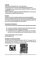
Table of Contents Box Contents ...6 OptionalItems ...6 GA-P35-DS3L/S3L Motherboard Layout 7 Block Diagram ...8 Chapter 1 Hardware Installation 9 1-1 Installation Precautions 9 1-2 Product Specifications 10 1-3 Installing the CPU and CPU Cooler... Memory 17 1-5 Installing an Expansion Card 18 1-6 Back Panel Connectors 19 1-7 Internal Connectors 21 Chapter 2 BIOS Setup 31 2-1 Startup Screen 32 2-2 The Main Menu 33 2-3 Standard CMOS Features 35 2-4 Advanced BIOS Features 37 2-5 IntegratedPeripherals 39 2-6 Power Management Setup 42 2-7 PnP/PCI Configurations 44 2-8 PC Health Status ...
Table of Contents Box Contents ...6 OptionalItems ...6 GA-P35-DS3L/S3L Motherboard Layout 7 Block Diagram ...8 Chapter 1 Hardware Installation 9 1-1 Installation Precautions 9 1-2 Product Specifications 10 1-3 Installing the CPU and CPU Cooler... Memory 17 1-5 Installing an Expansion Card 18 1-6 Back Panel Connectors 19 1-7 Internal Connectors 21 Chapter 2 BIOS Setup 31 2-1 Startup Screen 32 2-2 The Main Menu 33 2-3 Standard CMOS Features 35 2-4 Advanced BIOS Features 37 2-5 IntegratedPeripherals 39 2-6 Power Management Setup 42 2-7 PnP/PCI Configurations 44 2-8 PC Health Status ...

Manual
Page 5
... 54 3-3 Driver CD Information 54 3-4 Hardware Information 55 3-5 Contact Us ...55 Chapter 4 Unique Features 57 4-1 Xpress Recovery2 57 4-2 BIOS Update Utilities 62 4-2-1 Updating the BIOS with the Q-Flash Utility 62 4-2-2 Updating the BIOS with the @BIOS Utility 65 4-3 EasyTune 5 ...67 4-4 Windows Vista ReadyBoost 68 Chapter 5 Appendix ...69 5-1 Configuring Audio Input and Output 69 5-1-1 Configuring...
... 54 3-3 Driver CD Information 54 3-4 Hardware Information 55 3-5 Contact Us ...55 Chapter 4 Unique Features 57 4-1 Xpress Recovery2 57 4-2 BIOS Update Utilities 62 4-2-1 Updating the BIOS with the Q-Flash Utility 62 4-2-2 Updating the BIOS with the @BIOS Utility 65 4-3 EasyTune 5 ...67 4-4 Windows Vista ReadyBoost 68 Chapter 5 Appendix ...69 5-1 Configuring Audio Input and Output 69 5-1-1 Configuring...

Manual
Page 7
GA-P35-DS3L/S3L Motherboard Layout KB_MS COAXIAL OPTICAL ATX_12V LGA775 CPU_FAN ATX COM LPT DDRII1 GA-P35-DS3L/S3L R_USB SYS_FAN2 USB LAN F_AUDIO AUDIO SYS_FAN1 PCIE_3 RTL8111B PCIE_16 PCIE_1 SPDIF_O CODEC PCIE_2 SPDIF_I PCI1 PCI2 IT8718 PCI3 CD_IN Intel® P35 FDD DDRII3 DDRII4 DDRII2 PWR_FAN Intel® ICH9 BATTERY CLR_CMOS SATAII0 SATAII1 JMicron 368 SATAII4 BIOS SATAII5 IDE1 F_USB3 F_USB2 F_USB1 CI F_PANEL PWR_LED "*" Only the GA-P35-DS3L adopts All-Solid Capacitor design. - 7 -
GA-P35-DS3L/S3L Motherboard Layout KB_MS COAXIAL OPTICAL ATX_12V LGA775 CPU_FAN ATX COM LPT DDRII1 GA-P35-DS3L/S3L R_USB SYS_FAN2 USB LAN F_AUDIO AUDIO SYS_FAN1 PCIE_3 RTL8111B PCIE_16 PCIE_1 SPDIF_O CODEC PCIE_2 SPDIF_I PCI1 PCI2 IT8718 PCI3 CD_IN Intel® P35 FDD DDRII3 DDRII4 DDRII2 PWR_FAN Intel® ICH9 BATTERY CLR_CMOS SATAII0 SATAII1 JMicron 368 SATAII4 BIOS SATAII5 IDE1 F_USB3 F_USB2 F_USB1 CI F_PANEL PWR_LED "*" Only the GA-P35-DS3L adopts All-Solid Capacitor design. - 7 -
Manual
Page 8
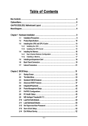
Block Diagram PCIe CLK (100 MHz) LGA775 Processor CPU CLK+/(333/266/200 MHz) PCI Express x16 LAN ATA-133/100/66/33 IDE Channel JMicron 368 x1 PCI Express Bus RJ45 RTL 8111B x1 3 PCI Express x1 x 1 x1 x1 PCIe CLK (100 MHz) PCI Bus Host Interface DDR2 1066/800/667 MHz Intel® P35 Dual Channel Memory MCH CLK (333/266/200 MHz) Intel® ICH9 BIOS 4 SATA 3Gb/s 12 USB Ports CODEC IT8718 Floppy LPT Port COM Port PS/2 KB/Mouse Surround Speaker Out Center/Subwoofer Speaker Out Side Speaker Out MIC Line-Out Line-In SPDIF In SPDIF Out 3 PCI PCI CLK (33 MHz) - 8 -
Block Diagram PCIe CLK (100 MHz) LGA775 Processor CPU CLK+/(333/266/200 MHz) PCI Express x16 LAN ATA-133/100/66/33 IDE Channel JMicron 368 x1 PCI Express Bus RJ45 RTL 8111B x1 3 PCI Express x1 x 1 x1 x1 PCIe CLK (100 MHz) PCI Bus Host Interface DDR2 1066/800/667 MHz Intel® P35 Dual Channel Memory MCH CLK (333/266/200 MHz) Intel® ICH9 BIOS 4 SATA 3Gb/s 12 USB Ports CODEC IT8718 Floppy LPT Port COM Port PS/2 KB/Mouse Surround Speaker Out Center/Subwoofer Speaker Out Side Speaker Out MIC Line-Out Line-In SPDIF In SPDIF Out 3 PCI PCI CLK (33 MHz) - 8 -
Manual
Page 11
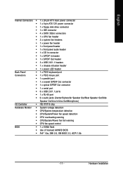
... temperature detection Š CPU/System/Power fan speed detection Š CPU overheating warning Š CPU/System/Power fan fail warning Š CPU fan speed control BIOS Š 1 x 8 Mbit flash Š Use of licensed AWARD BIOS Š PnP 1.0a, DMI 2.0, SM BIOS 2.3, ACPI 1.0b - 11 - Hardware Installation
... temperature detection Š CPU/System/Power fan speed detection Š CPU overheating warning Š CPU/System/Power fan fail warning Š CPU fan speed control BIOS Š 1 x 8 Mbit flash Š Use of licensed AWARD BIOS Š PnP 1.0a, DMI 2.0, SM BIOS 2.3, ACPI 1.0b - 11 - Hardware Installation
Manual
Page 12
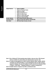
GA-P35-DS3L/S3L Motherboard - 12 - English Unique Features Bundled Software Operating System Form Factor Š Support for @BIOS Š Support for Download Center Š Support for Q-Flash Š Support for EasyTune (Note 3) Š Support for Xpress Install Š Support for Xpress Recovery2 Š Support for Virtual Dual BIOS &#...plug is supported in Windows Vista only) and configure the SATA connectors for AHCI mode. (Refer to Chapter 2, "BIOS Setup," "Integrated Peripherals," for details on enabling AHCI.) (Note 3) Available functions in Easytune may differ by motherboard model.
GA-P35-DS3L/S3L Motherboard - 12 - English Unique Features Bundled Software Operating System Form Factor Š Support for @BIOS Š Support for Download Center Š Support for Q-Flash Š Support for EasyTune (Note 3) Š Support for Xpress Install Š Support for Xpress Recovery2 Š Support for Virtual Dual BIOS &#...plug is supported in Windows Vista only) and configure the SATA connectors for AHCI mode. (Refer to Chapter 2, "BIOS Setup," "Integrated Peripherals," for details on enabling AHCI.) (Note 3) Available functions in Easytune may differ by motherboard model.
Manual
Page 13
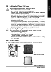
...that supports HT Technology • A chipset that supports HT Technology • An operating system that the motherboard supports the CPU. (Go to GIGABYTE's website for instructions on the computer if the CPU cooler is not installed, otherwise overheating and damage of the CPU Socket Notch - 13 ... power cord from the power outlet before you wish to set beyond the standard specifications, please do so according to Chapter 2, "BIOS Setup," "Advanced BIOS Features," for the latest CPU support list.) • Always turn on enabling the HT Technology.) 1-3-1 Installing the CPU A. The...
...that supports HT Technology • A chipset that supports HT Technology • An operating system that the motherboard supports the CPU. (Go to GIGABYTE's website for instructions on the computer if the CPU cooler is not installed, otherwise overheating and damage of the CPU Socket Notch - 13 ... power cord from the power outlet before you wish to set beyond the standard specifications, please do so according to Chapter 2, "BIOS Setup," "Advanced BIOS Features," for the latest CPU support list.) • Always turn on enabling the HT Technology.) 1-3-1 Installing the CPU A. The...
Manual
Page 16
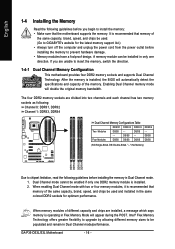
...and supports Dual Channel Technology. Four Modules DS/SS DS/SS DS/SS DDRII4 - GA-P35-DS3L/S3L Motherboard - 16 - Enabling Dual Channel memory mode will appear during the POST. ...a message which says memory is operating in only one DDR2 memory module is installed, the BIOS will automatically detect the specifications and capacity of the memory. DS/SS - - DS/SS... DDRII4 Due to chipset limitation, read the following guidelines before installing the memory to GIGABYTE's website for optimum performance. Intel® Flex Memory Technology offers greater flexibility to ...
...and supports Dual Channel Technology. Four Modules DS/SS DS/SS DS/SS DDRII4 - GA-P35-DS3L/S3L Motherboard - 16 - Enabling Dual Channel memory mode will appear during the POST. ...a message which says memory is operating in only one DDR2 memory module is installed, the BIOS will automatically detect the specifications and capacity of the memory. DS/SS - - DS/SS... DDRII4 Due to chipset limitation, read the following guidelines before installing the memory to GIGABYTE's website for optimum performance. Intel® Flex Memory Technology offers greater flexibility to ...
Manual
Page 18
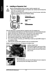
Remove the metal slot cover from the slot. Secure the card's metal bracket to correctly install your card. GA-P35-DS3L/S3L Motherboard - 18 - After installing all expansion cards, replace the chassis cover(s). 6. Carefully read the manual that supports your expansion card ...into the slot. 4. Turn on the card are completely inserted into the PCI Express x16 slot. If necessary, go to BIOS Setup to make any required BIOS changes for your computer. English 1-5 Installing an Expansion Card Read the following guidelines before installing an expansion card to prevent ...
Remove the metal slot cover from the slot. Secure the card's metal bracket to correctly install your card. GA-P35-DS3L/S3L Motherboard - 18 - After installing all expansion cards, replace the chassis cover(s). 6. Carefully read the manual that supports your expansion card ...into the slot. 4. Turn on the card are completely inserted into the PCI Express x16 slot. If necessary, go to BIOS Setup to make any required BIOS changes for your computer. English 1-5 Installing an Expansion Card Read the following guidelines before installing an expansion card to prevent ...
Manual
Page 25
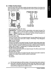
...LED Connects to indicate the problem. One single short beep will be heard if no problem is operating. If a problem is detected, the BIOS may issue beeps in different patterns to the power status indicator on the chassis front panel. A front panel module mainly consists of power ...SPEAK (Speaker, Orange): Connects to the power switch on the chassis front panel. When connecting your system using the power switch (refer to Chapter 2, "BIOS Setup," "Power Management Setup," for information about beep codes. • HD (IDE Hard Drive Activity LED, Blue) Connects to the reset switch on...
...LED Connects to indicate the problem. One single short beep will be heard if no problem is operating. If a problem is detected, the BIOS may issue beeps in different patterns to the power status indicator on the chassis front panel. A front panel module mainly consists of power ...SPEAK (Speaker, Orange): Connects to the power switch on the chassis front panel. When connecting your system using the power switch (refer to Chapter 2, "BIOS Setup," "Power Management Setup," for information about beep codes. • HD (IDE Hard Drive Activity LED, Blue) Connects to the reset switch on...

Manual
Page 29
...to temporarily short the two pins or use a metal object like a screwdriver to touch the two pins for BIOS configurations). - 29 - Hardware Installation date information and BIOS configurations) and reset the CMOS values to clear the CMOS values (e.g. To clear the CMOS values, place a... jumper cap on your computer, be sure to Chapter 2, "BIOS Setup," for a few seconds. This function requires a chassis with chassis intrusion detection design. Definition 1 1 Signal 2 GND 18) CLR_CMOS (Clearing CMOS...
...to temporarily short the two pins or use a metal object like a screwdriver to touch the two pins for BIOS configurations). - 29 - Hardware Installation date information and BIOS configurations) and reset the CMOS values to clear the CMOS values (e.g. To clear the CMOS values, place a... jumper cap on your computer, be sure to Chapter 2, "BIOS Setup," for a few seconds. This function requires a chassis with chassis intrusion detection design. Definition 1 1 Signal 2 GND 18) CLR_CMOS (Clearing CMOS...
Manual
Page 30
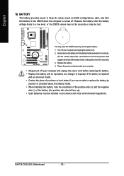
...; Always turn off your computer and unplug the power cord. 2. Gently remove the battery from the battery holder and wait for 5 seconds.) 3. GA-P35-DS3L/S3L Motherboard - 30 - Replace the battery. 4. Danger of the battery (the positive side should face up). • Used batteries must be ...lost. Replace the battery when the battery voltage drops to keep the values (such as BIOS configurations, date, and time information) in accordance with local environmental regulations. English 19) BATTERY The battery provides power to a low level...
...; Always turn off your computer and unplug the power cord. 2. Gently remove the battery from the battery holder and wait for 5 seconds.) 3. GA-P35-DS3L/S3L Motherboard - 30 - Replace the battery. 4. Danger of the battery (the positive side should face up). • Used batteries must be ...lost. Replace the battery when the battery voltage drops to keep the values (such as BIOS configurations, date, and time information) in accordance with local environmental regulations. English 19) BATTERY The battery provides power to a low level...
Manual
Page 31
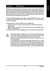
...you need to) to keep the configuration values in the CMOS on . For instructions on using the Q-Flash and @BIOS utilities, refer to Chapter 4, "BIOS Update Utilities." • Because BIOS flashing is potentially risky, if you can press + in system's failure to clear the CMOS values.) - 31 -...system instability or other unexpected results. To upgrade the BIOS, use either the GIGABYTE Q-Flash or @BIOS utility. • Q-Flash allows the user to quickly and easily upgrade or back up BIOS without entering the operating system. • @BIOS is a Windows-based utility that allows the user ...
...you need to) to keep the configuration values in the CMOS on . For instructions on using the Q-Flash and @BIOS utilities, refer to Chapter 4, "BIOS Update Utilities." • Because BIOS flashing is potentially risky, if you can press + in system's failure to clear the CMOS values.) - 31 -...system instability or other unexpected results. To upgrade the BIOS, use either the GIGABYTE Q-Flash or @BIOS utility. • Q-Flash allows the user to quickly and easily upgrade or back up BIOS without entering the operating system. • @BIOS is a Windows-based utility that allows the user ...
Manual
Page 32
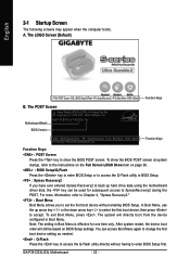
A. To show the BIOS POST screen. The system will still be used for subsequent access to access the Q-Flash utility in Boot Menu. GA-P35-DS3L/S3L Motherboard - 32 - In Boot Menu, use the up hard drive data using the motherboard driver disk, the key can access Boot Menu ...again to change the first boot device setting as needed. : Q-Flash Press the key to enter BIOS Setup first. For more information,...
A. To show the BIOS POST screen. The system will still be used for subsequent access to access the Q-Flash utility in Boot Menu. GA-P35-DS3L/S3L Motherboard - 32 - In Boot Menu, use the up hard drive data using the motherboard driver disk, the key can access Boot Menu ...again to change the first boot device setting as needed. : Q-Flash Press the key to enter BIOS Setup first. For more information,...
Manual
Page 33
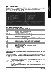
...stable as shown below) appears on the bottom line of the Main Menu. BIOS Setup Use arrow keys to move among the items and press to accept or enter a sub-menu. (Sample BIOS Version: GA-P35-DS3L F3a) CMOS Setup Utility-Copyright (C) 1984-2007 Award Software ` Standard CMOS ...Features ` Advanced BIOS Features ` Integrated Peripherals ` Power Management Setup ` PnP/PCI Configurations ` PC Health Status ` MB...
...stable as shown below) appears on the bottom line of the Main Menu. BIOS Setup Use arrow keys to move among the items and press to accept or enter a sub-menu. (Sample BIOS Version: GA-P35-DS3L F3a) CMOS Setup Utility-Copyright (C) 1984-2007 Award Software ` Standard CMOS ...Features ` Advanced BIOS Features ` Integrated Peripherals ` Power Management Setup ` PnP/PCI Configurations ` PC Health Status ` MB...
Manual
Page 34
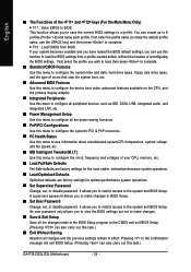
...time and date, hard drive types, floppy disk drive types, and the type of errors that stop the system boot, etc. „ Advanced BIOS Features Use this menu to configure the device boot order, advanced features available on the CPU, and the primary display adapter. „ Integrated ... „ MB Intelligent Tweaker(M.I.T.) Use this task.) GA-P35-DS3L/S3L Motherboard - 34 - English „ The Functions of the and keys (For the Main Menu Only) ` F11 : Save CMOS to BIOS This function allows you to restrict access to the system and BIOS Setup. An user password only allows you to restrict ...
...time and date, hard drive types, floppy disk drive types, and the type of errors that stop the system boot, etc. „ Advanced BIOS Features Use this menu to configure the device boot order, advanced features available on the CPU, and the primary display adapter. „ Integrated ... „ MB Intelligent Tweaker(M.I.T.) Use this task.) GA-P35-DS3L/S3L Motherboard - 34 - English „ The Functions of the and keys (For the Main Menu Only) ` F11 : Save CMOS to BIOS This function allows you to restrict access to the system and BIOS Setup. An user password only allows you to restrict ...
Manual
Page 35
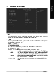
...the time. IDE Channel 0, 1 Master Configure your IDE/SATA devices by using one of the three methods below: • Auto Lets BIOS automatically detect IDE/SATA devices during the POST for faster system startup. • Manual Allows you to manually enter the specifications of the ...during the POST. (Default) • None If no IDE/SATA devices are : Auto (default), CHS, LBA, Large. - 35 - For example, 1 p.m. BIOS Setup English 2-3 Standard CMOS Features Date (mm:dd:yy) Time (hh:mm:ss) CMOS Setup Utility-Copyright (C) 1984-2007 Award Software Standard CMOS Features Fri...
...the time. IDE Channel 0, 1 Master Configure your IDE/SATA devices by using one of the three methods below: • Auto Lets BIOS automatically detect IDE/SATA devices during the POST for faster system startup. • Manual Allows you to manually enter the specifications of the ...during the POST. (Default) • None If no IDE/SATA devices are : Auto (default), CHS, LBA, Large. - 35 - For example, 1 p.m. BIOS Setup English 2-3 Standard CMOS Features Date (mm:dd:yy) Time (hh:mm:ss) CMOS Setup Utility-Copyright (C) 1984-2007 Award Software Standard CMOS Features Fri...
Manual
Page 36
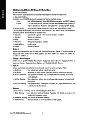
... disk drive, a Japanese standard floppy disk drive. Options are determined by using one of the two methods below: • Auto Lets BIOS automatically detect IDE/SATA devices during the POST. (Default) • None If no IDE/SATA devices are used, set this channel. ...devices by the BIOS POST. Access Mode Sets the hard drive access mode. Halt on this item to None. Capacity Approximate capacity of cylinders. Cylinder Number of the currently installed hard drive. Memory These fields are read-only and are : Disabled (default), Drive A. GA-P35-DS3L/S3L Motherboard - ...
... disk drive, a Japanese standard floppy disk drive. Options are determined by using one of the two methods below: • Auto Lets BIOS automatically detect IDE/SATA devices during the POST. (Default) • None If no IDE/SATA devices are used, set this channel. ...devices by the BIOS POST. Access Mode Sets the hard drive access mode. Halt on this item to None. Capacity Approximate capacity of cylinders. Cylinder Number of the currently installed hard drive. Memory These fields are read-only and are : Disabled (default), Drive A. GA-P35-DS3L/S3L Motherboard - ...
Manual
Page 37
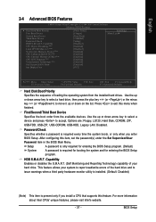
...the operating system from the available devices. Press to accept. Password Check Specifies whether a password is required for booting the system and for entering the BIOS Setup program. (Default) A password is required every time the system boots, or only when you install a CPU that supports this item, set ...the password(s) under the Set Supervisor/User Password item in the BIOS Main Menu. Use the up or down arrow key to select a device and press to exit this menu when finished. For more information ...
...the operating system from the available devices. Press to accept. Password Check Specifies whether a password is required for booting the system and for entering the BIOS Setup program. (Default) A password is required every time the system boots, or only when you install a CPU that supports this item, set ...the password(s) under the Set Supervisor/User Password item in the BIOS Main Menu. Use the up or down arrow key to select a device and press to exit this menu when finished. For more information ...


