
Manual
Page 3
...GIGABYTE provides the following types of documentations: „ For quick set-up of GIGABYTE.... All rights reserved. The logo is 1.0. by any form or by GIGA-BYTE TECHNOLOGY CO., LTD. GIGABYTE UNITED INC. Disclaimer Information in this manual is protected by copyright laws and is designated by GIGABYTE without GIGABYTE...'s prior written permission. For product-related information, check on our website at: http://www.gigabyte...legally registered to GIGABYTE UNITED INC....to use GIGABYTE's unique features, read or download...
...GIGABYTE provides the following types of documentations: „ For quick set-up of GIGABYTE.... All rights reserved. The logo is 1.0. by any form or by GIGA-BYTE TECHNOLOGY CO., LTD. GIGABYTE UNITED INC. Disclaimer Information in this manual is protected by copyright laws and is designated by GIGABYTE without GIGABYTE...'s prior written permission. For product-related information, check on our website at: http://www.gigabyte...legally registered to GIGABYTE UNITED INC....to use GIGABYTE's unique features, read or download...

Manual
Page 4
Table of Contents Box Contents ...6 OptionalItems ...6 GA-P31-DS3/DS3L/S3L Motherboard Layout 7 Block Diagram ...8 Chapter 1 Hardware Installation 9 1-1 Installation Precautions 9 1-2 Product Specifications 10 1-3 Installing the CPU and CPU ... Memory 17 1-5 Installing an Expansion Card 18 1-6 Back Panel Connectors 19 1-7 Internal Connectors 21 Chapter 2 BIOS Setup 31 2-1 Startup Screen 32 2-2 The Main Menu 33 2-3 Standard CMOS Features 35 2-4 Advanced BIOS Features 37 2-5 IntegratedPeripherals 39 2-6 Power Management Setup 42 2-7 PnP/PCI Configurations 44 2-8 PC Health Status...
Table of Contents Box Contents ...6 OptionalItems ...6 GA-P31-DS3/DS3L/S3L Motherboard Layout 7 Block Diagram ...8 Chapter 1 Hardware Installation 9 1-1 Installation Precautions 9 1-2 Product Specifications 10 1-3 Installing the CPU and CPU ... Memory 17 1-5 Installing an Expansion Card 18 1-6 Back Panel Connectors 19 1-7 Internal Connectors 21 Chapter 2 BIOS Setup 31 2-1 Startup Screen 32 2-2 The Main Menu 33 2-3 Standard CMOS Features 35 2-4 Advanced BIOS Features 37 2-5 IntegratedPeripherals 39 2-6 Power Management Setup 42 2-7 PnP/PCI Configurations 44 2-8 PC Health Status...
Manual
Page 5
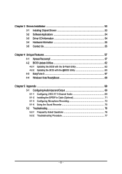
... 54 3-3 Driver CD Information 54 3-4 Hardware Information 55 3-5 Contact Us ...55 Chapter 4 Unique Features 57 4-1 Xpress Recovery2 57 4-2 BIOS Update Utilities 62 4-2-1 Updating the BIOS with the Q-Flash Utility 62 4-2-2 Updating the BIOS with the @BIOS Utility 65 4-3 EasyTune 5 ...67 4-4 Windows Vista ReadyBoost 68 Chapter 5 Appendix ...69 5-1 Configuring Audio Input and Output 69 5-1-1 Configuring...
... 54 3-3 Driver CD Information 54 3-4 Hardware Information 55 3-5 Contact Us ...55 Chapter 4 Unique Features 57 4-1 Xpress Recovery2 57 4-2 BIOS Update Utilities 62 4-2-1 Updating the BIOS with the Q-Flash Utility 62 4-2-2 Updating the BIOS with the @BIOS Utility 65 4-3 EasyTune 5 ...67 4-4 Windows Vista ReadyBoost 68 Chapter 5 Appendix ...69 5-1 Configuring Audio Input and Output 69 5-1-1 Configuring...

Manual
Page 7
GA-P31-DS3/DS3L/S3L Motherboard Layout KB_MS COAXIAL OPTICAL ATX_12V LGA775 CPU_FAN COMA LPT PWR_FAN GA-P31-DS3/DS3L/S3L USB USB LAN F_AUDIO Intel® P31 AUDIO SYS_FAN1 DDRII1 PCIE_3 ATX CD_IN RTL8111B PCIE_16 DDRII2 DDRII3 DDRII4 PCIE_1 CLR_CMOS SPDIF_O CODEC PCIE_2 PCI1 SPDIF_I PCI2 IT8718 PCI3 CI FDD Intel® ICH7 BAT SATAII0 SATAII2 SYS_FAN2 BIOS SATAII1 SATAII3 IDE1 PWR_LED F_PANEL F_USB1 F_USB2 "*" Only the GA-P31-DS3/DS3L adopts All-Solid Capacitor design. - 7 -
GA-P31-DS3/DS3L/S3L Motherboard Layout KB_MS COAXIAL OPTICAL ATX_12V LGA775 CPU_FAN COMA LPT PWR_FAN GA-P31-DS3/DS3L/S3L USB USB LAN F_AUDIO Intel® P31 AUDIO SYS_FAN1 DDRII1 PCIE_3 ATX CD_IN RTL8111B PCIE_16 DDRII2 DDRII3 DDRII4 PCIE_1 CLR_CMOS SPDIF_O CODEC PCIE_2 PCI1 SPDIF_I PCI2 IT8718 PCI3 CI FDD Intel® ICH7 BAT SATAII0 SATAII2 SYS_FAN2 BIOS SATAII1 SATAII3 IDE1 PWR_LED F_PANEL F_USB1 F_USB2 "*" Only the GA-P31-DS3/DS3L adopts All-Solid Capacitor design. - 7 -
Manual
Page 8
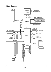
Block Diagram PCIe CLK (100 MHz) LGA775 Processor CPU CLK+/(333/266/200 MHz) PCI Express Bus PCI Express x16 LAN RJ45 RTL 8111B x1 3 PCI Express x1 x 1 x1 x1 PCIe CLK (100 MHz) PCI Bus Host Interface DDR2 800/667 MHz Intel® P31 Dual Channel Memory MCH CLK (333/266/200 MHz) Intel® ICH7 CODEC BIOS ATA-100/66/33 IDE Channel 4 SATA 3Gb/s 8 USB Ports IT8718 Floppy LPT Port COM Port PS/2 KB/Mouse Surround Speaker Out Center/Subwoofer Speaker Out Side Speaker Out MIC Line-Out Line-In SPDIF In SPDIF Out 3 PCI PCI CLK (33 MHz) - 8 -
Block Diagram PCIe CLK (100 MHz) LGA775 Processor CPU CLK+/(333/266/200 MHz) PCI Express Bus PCI Express x16 LAN RJ45 RTL 8111B x1 3 PCI Express x1 x 1 x1 x1 PCIe CLK (100 MHz) PCI Bus Host Interface DDR2 800/667 MHz Intel® P31 Dual Channel Memory MCH CLK (333/266/200 MHz) Intel® ICH7 CODEC BIOS ATA-100/66/33 IDE Channel 4 SATA 3Gb/s 8 USB Ports IT8718 Floppy LPT Port COM Port PS/2 KB/Mouse Surround Speaker Out Center/Subwoofer Speaker Out Side Speaker Out MIC Line-Out Line-In SPDIF In SPDIF Out 3 PCI PCI CLK (33 MHz) - 8 -

Manual
Page 11
... temperature detection Š CPU/System/Power fan speed detection Š CPU overheating warning Š CPU/System/Power fan fail warning Š CPU fan speed control BIOS Š 1 x 4 Mbit flash Š Use of licensed AWARD BIOS Š PnP 1.0a, DMI 2.0, SM BIOS 2.3, ACPI 1.0b - 11 - Hardware Installation
... temperature detection Š CPU/System/Power fan speed detection Š CPU overheating warning Š CPU/System/Power fan fail warning Š CPU fan speed control BIOS Š 1 x 4 Mbit flash Š Use of licensed AWARD BIOS Š PnP 1.0a, DMI 2.0, SM BIOS 2.3, ACPI 1.0b - 11 - Hardware Installation
Manual
Page 12
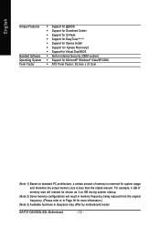
GA-P31-DS3/DS3L/S3L Motherboard - 12 - English Unique Features Bundled Software Operating System Form Factor Š Support for @BIOS Š Support for Download Center Š Support for Q-Flash Š Support for EasyTune (Note 3) Š Support for Xpress Install Š Support for Xpress Recovery2 Š Support for Virtual Dual BIOS Š Norton Internet Security (OEM version...
GA-P31-DS3/DS3L/S3L Motherboard - 12 - English Unique Features Bundled Software Operating System Form Factor Š Support for @BIOS Š Support for Download Center Š Support for Q-Flash Š Support for EasyTune (Note 3) Š Support for Xpress Install Š Support for Xpress Recovery2 Š Support for Virtual Dual BIOS Š Norton Internet Security (OEM version...

Manual
Page 13
...set the frequency beyond hardware specifications since it enabled (Refer to Chapter 2, "BIOS Setup," "Advanced BIOS Features," for instructions on the CPU Hardware Installation It is not installed, ...A chipset that supports HT Technology • An operating system that is optimized for HT Technology • A BIOS that supports HT Technology and has it does not meet the standard requirements for the peripherals. Locate the alignment ...Make sure that the motherboard supports the CPU. (Go to GIGABYTE's website for the latest CPU support list.) • Always turn on the CPU.
...set the frequency beyond hardware specifications since it enabled (Refer to Chapter 2, "BIOS Setup," "Advanced BIOS Features," for instructions on the CPU Hardware Installation It is not installed, ...A chipset that supports HT Technology • An operating system that is optimized for HT Technology • A BIOS that supports HT Technology and has it does not meet the standard requirements for the peripherals. Locate the alignment ...Make sure that the motherboard supports the CPU. (Go to GIGABYTE's website for the latest CPU support list.) • Always turn on the CPU.

Manual
Page 16
..., it is installed, the BIOS will double the original memory bandwidth. The four DDR2 memory sockets are unable to prevent hardware damage. • Memory modules have a foolproof design. DS/SS DS/SS - - - - DS/SS - - Dual Channel mode cannot be used . (Go to GIGABYTE's website for optimum performance. 3. GA-P31-DS3/DS3L/S3L Motherboard - 16 - English...
..., it is installed, the BIOS will double the original memory bandwidth. The four DDR2 memory sockets are unable to prevent hardware damage. • Memory modules have a foolproof design. DS/SS DS/SS - - - - DS/SS - - Dual Channel mode cannot be used . (Go to GIGABYTE's website for optimum performance. 3. GA-P31-DS3/DS3L/S3L Motherboard - 16 - English...

Manual
Page 18
Turn on your operating system. Install the driver provided with your card. GA-P31-DS3/DS3L/S3L Motherboard - 18 - Remove the metal slot cover from the slot. Secure the card's metal bracket to the chassis back panel with the slot, and ... Removing a PCI Express x16 Graphics Card: • Installing a Graphics Card: Gently insert the graphics card into the slot. 4. If necessary, go to BIOS Setup to make any required BIOS changes for your expansion card in the expansion slot. 1. Make sure the graphics card is fully seated in your computer. English 1-5 Installing an...
Turn on your operating system. Install the driver provided with your card. GA-P31-DS3/DS3L/S3L Motherboard - 18 - Remove the metal slot cover from the slot. Secure the card's metal bracket to the chassis back panel with the slot, and ... Removing a PCI Express x16 Graphics Card: • Installing a Graphics Card: Gently insert the graphics card into the slot. 4. If necessary, go to BIOS Setup to make any required BIOS changes for your expansion card in the expansion slot. 1. Make sure the graphics card is fully seated in your computer. English 1-5 Installing an...
Manual
Page 26
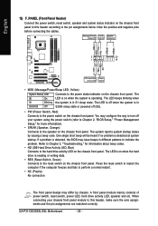
...chassis front panel. A front panel module mainly consists of power switch, reset switch, power LED, hard drive activity LED, speaker and etc. GA-P31-DS3/DS3L/S3L Motherboard - 26 - Note the positive and negative pins before connecting the cables. Message/Power/ Power Speaker Sleep LED Switch Connector MSG+ ...the chassis front panel. The LED is on the chassis front panel. When connecting your system using the power switch (refer to Chapter 2, "BIOS Setup," "Power Management Setup," for information about beep codes. • HD (IDE Hard Drive Activity LED, Blue) Connects to the power ...
...chassis front panel. A front panel module mainly consists of power switch, reset switch, power LED, hard drive activity LED, speaker and etc. GA-P31-DS3/DS3L/S3L Motherboard - 26 - Note the positive and negative pins before connecting the cables. Message/Power/ Power Speaker Sleep LED Switch Connector MSG+ ...the chassis front panel. The LED is on the chassis front panel. When connecting your system using the power switch (refer to Chapter 2, "BIOS Setup," "Power Management Setup," for information about beep codes. • HD (IDE Hard Drive Activity LED, Blue) Connects to the power ...

Manual
Page 29
...the CMOS values and before turning on the two pins to temporarily short the two pins or use a metal object like a screwdriver to Chapter 2, "BIOS Setup," for a few seconds. Failure to do so may cause damage to the motherboard. • After system restart, go to... BIOS Setup to load factory defaults (select Load Optimized Defaults) or manually configure the BIOS settings (refer to touch the two pins for BIOS configurations). - 29 - English 17) CI (Chassis Intrusion Header) This motherboard provides a chassis...
...the CMOS values and before turning on the two pins to temporarily short the two pins or use a metal object like a screwdriver to Chapter 2, "BIOS Setup," for a few seconds. Failure to do so may cause damage to the motherboard. • After system restart, go to... BIOS Setup to load factory defaults (select Load Optimized Defaults) or manually configure the BIOS settings (refer to touch the two pins for BIOS configurations). - 29 - English 17) CI (Chassis Intrusion Header) This motherboard provides a chassis...
Manual
Page 30
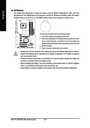
Gently remove the battery from the battery holder and wait for 5 seconds.) 3. GA-P31-DS3/DS3L/S3L Motherboard - 30 - Replace the battery. 4. Replace the battery when the battery voltage drops to touch the positive and negative terminals of the battery (the ... replaced with an incorrect model. • Contact the place of purchase or local dealer if you are not able to keep the values (such as BIOS configurations, date, and time information) in accordance with an equivalent one minute. (Or use a metal object like a screwdriver to a low level, or the CMOS values...
Gently remove the battery from the battery holder and wait for 5 seconds.) 3. GA-P31-DS3/DS3L/S3L Motherboard - 30 - Replace the battery. 4. Replace the battery when the battery voltage drops to touch the positive and negative terminals of the battery (the ... replaced with an incorrect model. • Contact the place of purchase or local dealer if you are not able to keep the values (such as BIOS configurations, date, and time information) in accordance with an equivalent one minute. (Or use a metal object like a screwdriver to a low level, or the CMOS values...
Manual
Page 31
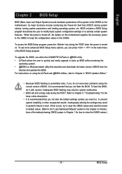
...certain system features. Its major functions include conducting the Power-On Self-Test (POST) during the POST. To upgrade the BIOS, use either the GIGABYTE Q-Flash or @BIOS utility. • Q-Flash allows the user to prevent system instability or other unexpected results. Inadequately altering the settings may...recommended that allows the user to modify basic system configuration settings or to clear the CMOS values.) - 31 - To see more advanced BIOS Setup menu options, you can press + in the CMOS on the motherboard supplies the necessary power to the CMOS to boot. For ...
...certain system features. Its major functions include conducting the Power-On Self-Test (POST) during the POST. To upgrade the BIOS, use either the GIGABYTE Q-Flash or @BIOS utility. • Q-Flash allows the user to prevent system instability or other unexpected results. Inadequately altering the settings may...recommended that allows the user to modify basic system configuration settings or to clear the CMOS values.) - 31 - To see more advanced BIOS Setup menu options, you can press + in the CMOS on the motherboard supplies the necessary power to the CMOS to boot. For ...

Manual
Page 32
...set the first boot device without having to access the Q-Flash utility directly without entering BIOS Setup. Motherboard Model BIOS Version Intel P31 BIOS for subsequent access to accept. For more information, refer to Chapter 4, "Xpress ...Recovery2." : Boot Menu Boot Menu allows you have ever entered Xpress Recovery2 to back up arrow key < > or the down arrow key< > to select the first boot device, then press to XpressRecovery2 during the POST. GA-P31-DS3/DS3L...
...set the first boot device without having to access the Q-Flash utility directly without entering BIOS Setup. Motherboard Model BIOS Version Intel P31 BIOS for subsequent access to accept. For more information, refer to Chapter 4, "Xpress ...Recovery2." : Boot Menu Boot Menu allows you have ever entered Xpress Recovery2 to back up arrow key < > or the down arrow key< > to select the first boot device, then press to XpressRecovery2 during the POST. GA-P31-DS3/DS3L...

Manual
Page 33
...exit the help screen (General Help) of function keys available for the menu. BIOS Setup Use arrow keys to move among the items and press to accept or enter a sub-menu. (Sample BIOS Version: GA-P31-DS3 E14) CMOS Setup Utility-Copyright (C) 1984-2007 Award Software ` Standard CMOS ...Features ` Advanced BIOS Features ` Integrated Peripherals ` Power Management Setup ` PnP/PCI Configurations ` PC Health Status ` ...
...exit the help screen (General Help) of function keys available for the menu. BIOS Setup Use arrow keys to move among the items and press to accept or enter a sub-menu. (Sample BIOS Version: GA-P31-DS3 E14) CMOS Setup Utility-Copyright (C) 1984-2007 Award Software ` Standard CMOS ...Features ` Advanced BIOS Features ` Integrated Peripherals ` Power Management Setup ` PnP/PCI Configurations ` PC Health Status ` ...

Manual
Page 34
... this menu to see information about autodetected system/CPU temperature, system voltage and fan speed, etc. „ MB Intelligent Tweaker(M.I.T.) Use this task.) GA-P31-DS3/DS3L/S3L Motherboard - 34 - It allows you to save the current BIOS settings to a profile. An user password only allows you to restrict access to the system and...
... this menu to see information about autodetected system/CPU temperature, system voltage and fan speed, etc. „ MB Intelligent Tweaker(M.I.T.) Use this task.) GA-P31-DS3/DS3L/S3L Motherboard - 34 - It allows you to save the current BIOS settings to a profile. An user password only allows you to restrict access to the system and...
Manual
Page 35
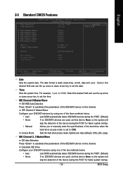
.... The date format is 13:0:0. IDE Channel 0 Master/Slave Configure your IDE/SATA devices using one of the two methods below : • Auto Lets BIOS automatically detect IDE/SATA devices during the POST. (Default) • None If no IDE/SATA devices are used , set the time. English 2-3 Standard ...use the up arrow or down arrow key to None so the system will skip the detection of the three methods below : • Auto Lets BIOS automatically detect IDE/SATA devices during the POST for faster system startup. - 35 - Options are used , set this item to set this item...
.... The date format is 13:0:0. IDE Channel 0 Master/Slave Configure your IDE/SATA devices using one of the two methods below : • Auto Lets BIOS automatically detect IDE/SATA devices during the POST. (Default) • None If no IDE/SATA devices are used , set the time. English 2-3 Standard ...use the up arrow or down arrow key to None so the system will skip the detection of the three methods below : • Auto Lets BIOS automatically detect IDE/SATA devices during the POST for faster system startup. - 35 - Options are used , set this item to set this item...

Manual
Page 36
... type of floppy disk drive installed in your hard drive specifications. Typically, 640 KB will stop for an error during the POST. GA-P31-DS3/DS3L/S3L Motherboard - 36 - Capacity Approximate capacity of cylinders. Cylinder Number of the currently installed hard drive. Sector Number of heads..../5.25", 720K/3.5", 1.44M/3.5", 2.88M/3.5". Head Number of sectors. Options are determined by the BIOS POST. No Errors The system boot will stop for all other errors. All Errors Whenever the BIOS detects a non-fatal error the system boot will not stop . All, But Disk/Key The...
... type of floppy disk drive installed in your hard drive specifications. Typically, 640 KB will stop for an error during the POST. GA-P31-DS3/DS3L/S3L Motherboard - 36 - Capacity Approximate capacity of cylinders. Cylinder Number of the currently installed hard drive. Sector Number of heads..../5.25", 720K/3.5", 1.44M/3.5", 2.88M/3.5". Head Number of sectors. Options are determined by the BIOS POST. No Errors The system boot will stop for all other errors. All Errors Whenever the BIOS detects a non-fatal error the system boot will not stop . All, But Disk/Key The...
Manual
Page 37
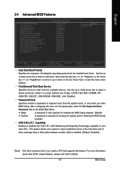
.../write errors of the hard drive and to exit this item, set the password(s) under the Set Supervisor/User Password item in the BIOS Main Menu. First/Second/Third Boot Device Specifies the boot order from the installed hard drives. Password Check Specifies whether a password is... time the system boots, or only when you install a CPU that supports this feature. Setup System A password is only required for entering the BIOS Setup program. Press to issue warnings when a third party hardware monitor utility is installed. (Default: Disabled) (Note) This item is required for...
.../write errors of the hard drive and to exit this item, set the password(s) under the Set Supervisor/User Password item in the BIOS Main Menu. First/Second/Third Boot Device Specifies the boot order from the installed hard drives. Password Check Specifies whether a password is... time the system boots, or only when you install a CPU that supports this feature. Setup System A password is only required for entering the BIOS Setup program. Press to issue warnings when a third party hardware monitor utility is installed. (Default: Disabled) (Note) This item is required for...


