Manual
Page 3
...: The logo is exclusively licensed to assist in this manual may be made by copyright laws and is protected by GIGABYTE without GIGABYTE's prior written permission. No part of this manual are legally registered to their respective owners. All rights reserved. The....tw Identifying Your Motherboard Revision The revision number on your motherboard revision before updating motherboard BIOS, drivers, or when looking for technical information. Documentation Classifications In order to GIGABYTE UNITED INC. by GIGA-BYTE TECHNOLOGY CO., LTD as the exclu- sive global distributor ...
...: The logo is exclusively licensed to assist in this manual may be made by copyright laws and is protected by GIGABYTE without GIGABYTE's prior written permission. No part of this manual are legally registered to their respective owners. All rights reserved. The....tw Identifying Your Motherboard Revision The revision number on your motherboard revision before updating motherboard BIOS, drivers, or when looking for technical information. Documentation Classifications In order to GIGABYTE UNITED INC. by GIGA-BYTE TECHNOLOGY CO., LTD as the exclu- sive global distributor ...
Manual
Page 4
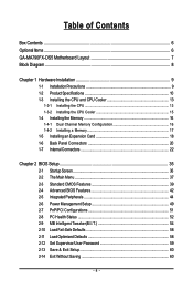
Table of Contents Box Contents ...6 OptionalItems ...6 GA-MA790FX-DS5 Motherboard Layout 7 Block Diagram ...8 Chapter 1 Hardware Installation 9 1-1 Installation Precautions 9 1-2 Product Specifications 10 1-3 Installing the CPU and CPU Cooler ... Memory 17 1-5 Installing an Expansion Card 18 1-6 Back Panel Connectors 20 1-7 Internal Connectors 22 Chapter 2 BIOS Setup 35 2-1 Startup Screen 36 2-2 The Main Menu 37 2-3 Standard CMOS Features 39 2-4 Advanced BIOS Features 42 2-5 IntegratedPeripherals 44 2-6 Power Management Setup 49 2-7 PnP/PCI Configurations 51 2-8 PC Health Status...
Table of Contents Box Contents ...6 OptionalItems ...6 GA-MA790FX-DS5 Motherboard Layout 7 Block Diagram ...8 Chapter 1 Hardware Installation 9 1-1 Installation Precautions 9 1-2 Product Specifications 10 1-3 Installing the CPU and CPU Cooler ... Memory 17 1-5 Installing an Expansion Card 18 1-6 Back Panel Connectors 20 1-7 Internal Connectors 22 Chapter 2 BIOS Setup 35 2-1 Startup Screen 36 2-2 The Main Menu 37 2-3 Standard CMOS Features 39 2-4 Advanced BIOS Features 42 2-5 IntegratedPeripherals 44 2-6 Power Management Setup 49 2-7 PnP/PCI Configurations 51 2-8 PC Health Status...
Manual
Page 5
... 63 3-5 Contact Us ...63 Chapter 4 Unique Features 65 4-1 Xpress Recovery2 65 4-2 BIOS Update Utilities 70 4-2-1 Updating the BIOS with the Q-Flash Utility 70 4-2-2 Updating the BIOS with the @BIOS Utility 73 4-3 EasyTune 5 Pro 75 4-4 Windows Vista ReadyBoost 76 Chapter 5 Appendix ...77... 5-1 Configuring SATA Hard Drive(s 77 5-1-1 Configuring AMD SB600 SATA Controllers 77 5-1-2 Configuring GIGABYTE SATA2 SATA Controller 83 5-1-3 Making...
... 63 3-5 Contact Us ...63 Chapter 4 Unique Features 65 4-1 Xpress Recovery2 65 4-2 BIOS Update Utilities 70 4-2-1 Updating the BIOS with the Q-Flash Utility 70 4-2-2 Updating the BIOS with the @BIOS Utility 73 4-3 EasyTune 5 Pro 75 4-4 Windows Vista ReadyBoost 76 Chapter 5 Appendix ...77... 5-1 Configuring SATA Hard Drive(s 77 5-1-1 Configuring AMD SB600 SATA Controllers 77 5-1-2 Configuring GIGABYTE SATA2 SATA Controller 83 5-1-3 Making...
Manual
Page 7
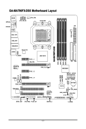
GA-MA790FX-DS5 Motherboard Layout KB_MS OPTICAL ATX_12V_2X CPU_FAN Socket AM2 COMA COAXIAL ATX V1394 USB_1394 PWR_FAN USB_LAN1 GA-MA790FX-DS5 DDRII_1 DDRII_2 DDRII_3 DDRII_4 USB_ESATA AUDIO RTL8111B F_AUDIO PCIE_1_1 NB_FAN AMD 790FX IDE FDD GIGABYTE SATA2 PCIE_1_2 PCIE_16_A AMD SB600 SATAII1 SATAII0 CD_IN SPDIF_IN CODEC PCIE_1_3 PCIE_16_B PCI1 TSB43AB23 PCI2 F_1394 GSATAII_1 SPDIF_OUT SYS_FAN2 PCIE_12V GIGABYTE SATA2 LPT GSATAII_2 F_USB1 F_USB2 SATAII3 SATAII2 Main BIOS BATTERY IT8718 Backup CLR_CMOS BIOS PWR_LED SYS_FAN1 CI F_PANEL - 7 -
GA-MA790FX-DS5 Motherboard Layout KB_MS OPTICAL ATX_12V_2X CPU_FAN Socket AM2 COMA COAXIAL ATX V1394 USB_1394 PWR_FAN USB_LAN1 GA-MA790FX-DS5 DDRII_1 DDRII_2 DDRII_3 DDRII_4 USB_ESATA AUDIO RTL8111B F_AUDIO PCIE_1_1 NB_FAN AMD 790FX IDE FDD GIGABYTE SATA2 PCIE_1_2 PCIE_16_A AMD SB600 SATAII1 SATAII0 CD_IN SPDIF_IN CODEC PCIE_1_3 PCIE_16_B PCI1 TSB43AB23 PCI2 F_1394 GSATAII_1 SPDIF_OUT SYS_FAN2 PCIE_12V GIGABYTE SATA2 LPT GSATAII_2 F_USB1 F_USB2 SATAII3 SATAII2 Main BIOS BATTERY IT8718 Backup CLR_CMOS BIOS PWR_LED SYS_FAN1 CI F_PANEL - 7 -

Manual
Page 8
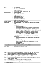
... x16 Bus 3 PCI Express x1 LAN RJ45 PCIe CLK (100 MHz) RTL8111B x1 PCI Express Bus 4 SATA 3Gb/s x1 GIGABYTE SATA2 x 2 AMD 790FX AMD SB600 PCI Bus TSB43AB23 3 IEEE 1394a CODEC Dual BIOS ATA-133/100/66/33 IDE Channel 4 SATA 3Gb/s 10 USB Ports IT8718 Floppy LPT Port COM Port PS...
... x16 Bus 3 PCI Express x1 LAN RJ45 PCIe CLK (100 MHz) RTL8111B x1 PCI Express Bus 4 SATA 3Gb/s x1 GIGABYTE SATA2 x 2 AMD 790FX AMD SB600 PCI Bus TSB43AB23 3 IEEE 1394a CODEC Dual BIOS ATA-133/100/66/33 IDE Channel 4 SATA 3Gb/s 10 USB Ports IT8718 Floppy LPT Port COM Port PS...
Manual
Page 12
... Š Support for Virtual Dual BIOS Š Norton Internet Security (OEM version) Š Voltage adjustments in BIOS Setup (CPU/DDR2/Chipset/PCIE/FSB/HTT/ HTR) allow you to: - Increase HTT voltage by 0.05V to 0.40V with 0.05V increment - GA-MA790FX-DS5 Motherboard - 12 - Increase Chipset voltage... by 0.05V to 0.40V with 0.05V increment - Adjust CPU host frequency from 100 MHz to 200 MHz with 0.05V increment Š Frequency adjustments in BIOS Setup (CPU/HT Link/PCIE/DDR2) allow ...
... Š Support for Virtual Dual BIOS Š Norton Internet Security (OEM version) Š Voltage adjustments in BIOS Setup (CPU/DDR2/Chipset/PCIE/FSB/HTT/ HTR) allow you to: - Increase HTT voltage by 0.05V to 0.40V with 0.05V increment - GA-MA790FX-DS5 Motherboard - 12 - Increase Chipset voltage... by 0.05V to 0.40V with 0.05V increment - Adjust CPU host frequency from 100 MHz to 200 MHz with 0.05V increment Š Frequency adjustments in BIOS Setup (CPU/HT Link/PCIE/DDR2) allow ...
Manual
Page 16
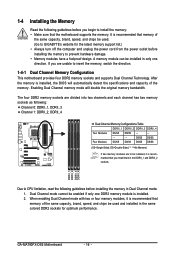
...the Memory Read the following guidelines before you install them in the DDRII_1 and DDRII_2 sockets. After the memory is installed, the BIOS will double the original memory bandwidth. DS/SS DS/SS Four Modules DS/SS DS/SS DS/SS DS/SS (SS=Single-... the memory in only one DDR2 memory module is recommended that the motherboard supports the memory. DDRII_1 DDRII_2 DDRII_3 DDRII_4 Due to GIGABYTE's website for optimum performance. GA-MA790FX-DS5 Motherboard - 16 - The four DDR2 memory sockets are unable to prevent hardware damage. • Memory modules have a foolproof design...
...the Memory Read the following guidelines before you install them in the DDRII_1 and DDRII_2 sockets. After the memory is installed, the BIOS will double the original memory bandwidth. DS/SS DS/SS Four Modules DS/SS DS/SS DS/SS DS/SS (SS=Single-... the memory in only one DDR2 memory module is recommended that the motherboard supports the memory. DDRII_1 DDRII_2 DDRII_3 DDRII_4 Due to GIGABYTE's website for optimum performance. GA-MA790FX-DS5 Motherboard - 16 - The four DDR2 memory sockets are unable to prevent hardware damage. • Memory modules have a foolproof design...
Manual
Page 18
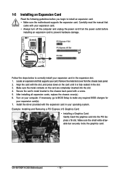
...the card's metal bracket to the chassis back panel with the expansion card in your operating system. If necessary, go to BIOS Setup to install an expansion card: • Make sure the motherboard supports the expansion card. Locate an expansion slot that... 6. Example: Installing and Removing a PCI Express x16 Graphics Card: • Installing a Graphics Card: Gently insert the graphics card into the slot. 4. GA-MA790FX-DS5 Motherboard - 18 - Install the driver provided with a screw. 5. Turn on the card are completely inserted into the PCI Express x16 slot. 1-5 Installing ...
...the card's metal bracket to the chassis back panel with the expansion card in your operating system. If necessary, go to BIOS Setup to install an expansion card: • Make sure the motherboard supports the expansion card. Locate an expansion slot that... 6. Example: Installing and Removing a PCI Express x16 Graphics Card: • Installing a Graphics Card: Gently insert the graphics card into the slot. 4. GA-MA790FX-DS5 Motherboard - 18 - Install the driver provided with a screw. 5. Turn on the card are completely inserted into the PCI Express x16 slot. 1-5 Installing ...
Manual
Page 28
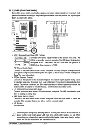
... sure the wire assignments and the pin assignments are matched correctly. When connecting your system using the power switch (refer to Chapter 2, "BIOS Setup," "Power Management Setup," for information about beep codes. • HD (IDE Hard Drive Activity LED, Blue) Connects to the ...Red): Connects to the hard drive activity LED on the chassis front panel. Message/Power/ Power Sleep LED Switch Speaker Connector MSG+ MSG- GA-MA790FX-DS5 Motherboard - 28 - The LED keeps blinking when S1 Blinking the system is detected at system startup. You may differ by issuing a beep...
... sure the wire assignments and the pin assignments are matched correctly. When connecting your system using the power switch (refer to Chapter 2, "BIOS Setup," "Power Management Setup," for information about beep codes. • HD (IDE Hard Drive Activity LED, Blue) Connects to the ...Red): Connects to the hard drive activity LED on the chassis front panel. Message/Power/ Power Sleep LED Switch Speaker Connector MSG+ MSG- GA-MA790FX-DS5 Motherboard - 28 - The LED keeps blinking when S1 Blinking the system is detected at system startup. You may differ by issuing a beep...

Manual
Page 32
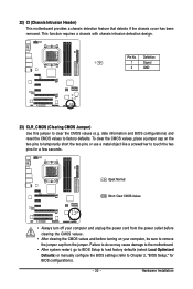
...PD6 GND PD7 GND ACKGND BUSY GND PE No Pin SLCT GND 21) BATTERY The battery provides power to keep the values (such as BIOS configurations, date, and time information) in accordance with local environmental regulations. Gently remove the battery from the battery holder and wait for ... the battery: 1. Plug in the power cord and restart your computer. • Always turn off your computer and unplug the power cord. 2. GA-MA790FX-DS5 Motherboard - 32 - You may be handled in the CMOS when the computer is replaced with an equivalent one. Turn off . Replace the battery....
...PD6 GND PD7 GND ACKGND BUSY GND PE No Pin SLCT GND 21) BATTERY The battery provides power to keep the values (such as BIOS configurations, date, and time information) in accordance with local environmental regulations. Gently remove the battery from the battery holder and wait for ... the battery: 1. Plug in the power cord and restart your computer. • Always turn off your computer and unplug the power cord. 2. GA-MA790FX-DS5 Motherboard - 32 - You may be handled in the CMOS when the computer is replaced with an equivalent one. Turn off . Replace the battery....
Manual
Page 33
...cause damage to the motherboard. • After system restart, go to BIOS Setup to load factory defaults (select Load Optimized Defaults) or manually configure the BIOS settings (refer to touch the two pins for BIOS configurations). - 33 - Hardware Installation To clear the CMOS values, place... values and before turning on the two pins to temporarily short the two pins or use a metal object like a screwdriver to Chapter 2, "BIOS Setup," for a few seconds. This function requires a chassis with chassis intrusion detection design. Definition 1 1 Signal 2 GND 23) CLR_CMOS (Clearing...
...cause damage to the motherboard. • After system restart, go to BIOS Setup to load factory defaults (select Load Optimized Defaults) or manually configure the BIOS settings (refer to touch the two pins for BIOS configurations). - 33 - Hardware Installation To clear the CMOS values, place... values and before turning on the two pins to temporarily short the two pins or use a metal object like a screwdriver to Chapter 2, "BIOS Setup," for a few seconds. This function requires a chassis with chassis intrusion detection design. Definition 1 1 Signal 2 GND 23) CLR_CMOS (Clearing...
Manual
Page 35
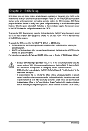
... saving system parameters and loading operating system, etc. To see more advanced BIOS Setup menu options, you can press + in the CMOS. For instructions on . To upgrade the BIOS, use either the GIGABYTE Q-Flash or @BIOS utility. • Q-Flash allows the user to quickly and easily upgrade ...or back up BIOS without entering the operating system. • @BIOS is a Windows-based utility that allows the user to modify ...
... saving system parameters and loading operating system, etc. To see more advanced BIOS Setup menu options, you can press + in the CMOS. For instructions on . To upgrade the BIOS, use either the GIGABYTE Q-Flash or @BIOS utility. • Q-Flash allows the user to quickly and easily upgrade ...or back up BIOS without entering the operating system. • @BIOS is a Windows-based utility that allows the user to modify ...
Manual
Page 36
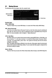
... < > or the down arrow key< > to select the first boot device, then press to enter BIOS Setup first. You can be based on BIOS Setup settings. GA-MA790FX-DS5 F1a . . . . : BIOS Setup : XpressRecovery2 : Boot Menu : Qflash 09/20/2007-RD790-SB600-6A66AG02C-00 Function Keys Function Keys...: : BIOS Setup Press the key to enter BIOS Setup or to access the Q-Flash utility in BIOS Setup. : Xpress Recovery2 If...
... < > or the down arrow key< > to select the first boot device, then press to enter BIOS Setup first. You can be based on BIOS Setup settings. GA-MA790FX-DS5 F1a . . . . : BIOS Setup : XpressRecovery2 : Boot Menu : Qflash 09/20/2007-RD790-SB600-6A66AG02C-00 Function Keys Function Keys...: : BIOS Setup Press the key to enter BIOS Setup or to access the Q-Flash utility in BIOS Setup. : Xpress Recovery2 If...

Manual
Page 37
... Program Function Keys Move the selection bar to select an item Execute command or enter the submenu Main Menu: Exit the BIOS Setup program Submenus: Exit current submenu Increase the numeric value or make changes Decrease the numeric value or make changes Show ...the Q-Flash utility Display system information Save all the changes and exit the BIOS Setup program Save CMOS to display a help screen. BIOS Setup 2-2 The Main Menu Once you want in a submenu, press to BIOS Load CMOS from BIOS Time, Date, Hard Disk Type... Press to exit the help screen ...
... Program Function Keys Move the selection bar to select an item Execute command or enter the submenu Main Menu: Exit the BIOS Setup program Submenus: Exit current submenu Increase the numeric value or make changes Decrease the numeric value or make changes Show ...the Q-Flash utility Display system information Save all the changes and exit the BIOS Setup program Save CMOS to display a help screen. BIOS Setup 2-2 The Main Menu Once you want in a submenu, press to BIOS Load CMOS from BIOS Time, Date, Hard Disk Type... Press to exit the help screen ...
Manual
Page 38
...Configurations Use this menu to configure the system's PCI & PnP resources. „ PC Health Status Use this menu to load the BIOS settings from BIOS If your CPU, memory, etc. „ Load Fail-Safe Defaults Fail-Safe defaults are factory settings for the most stable, minimal-...and voltages of your system becomes unstable and you have loaded the BIOS default settings, you can also carry out this function to see information about autodetected system/CPU temperature, system voltage and fan speed, etc. „ MB Intelligent Tweaker(M.I.T.) Use this task.) GA-MA790FX-DS5 Motherboard - 38 -
...Configurations Use this menu to configure the system's PCI & PnP resources. „ PC Health Status Use this menu to load the BIOS settings from BIOS If your CPU, memory, etc. „ Load Fail-Safe Defaults Fail-Safe defaults are factory settings for the most stable, minimal-...and voltages of your system becomes unstable and you have loaded the BIOS default settings, you can also carry out this function to see information about autodetected system/CPU temperature, system voltage and fan speed, etc. „ MB Intelligent Tweaker(M.I.T.) Use this task.) GA-MA790FX-DS5 Motherboard - 38 -

Manual
Page 39
... system date. The date format is 13:0:0. Select the desired field and use the up arrow or down arrow key to set the time. - 39 - BIOS Setup Select the desired field and use the up arrow or down arrow key to set the date.
... system date. The date format is 13:0:0. Select the desired field and use the up arrow or down arrow key to set the time. - 39 - BIOS Setup Select the desired field and use the up arrow or down arrow key to set the date.
Manual
Page 40
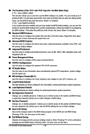
... hard drive access mode. Extended IDE Drive Configure your IDE/SATA devices by using one of the two methods below : • Auto Lets BIOS automatically detect IDE/SATA devices during the POST. (Default) • None If no IDE/SATA devices are used , set this item to ... to selects the type of the IDE/SATA device on this channel. GA-MA790FX-DS5 Motherboard - 40 - IDE Channel 0 Master/Slave Configure your IDE/SATA devices by using one of the three methods below : • Auto Lets BIOS automatically detect IDE/SATA devices during the POST for faster system startup. ...
... hard drive access mode. Extended IDE Drive Configure your IDE/SATA devices by using one of the two methods below : • Auto Lets BIOS automatically detect IDE/SATA devices during the POST. (Default) • None If no IDE/SATA devices are used , set this item to ... to selects the type of the IDE/SATA device on this channel. GA-MA790FX-DS5 Motherboard - 40 - IDE Channel 0 Master/Slave Configure your IDE/SATA devices by using one of the three methods below : • Auto Lets BIOS automatically detect IDE/SATA devices during the POST for faster system startup. ...

Manual
Page 41
...system. Extended Memory The amount of extended memory. - 41 - Base Memory Also called conventional memory. Typically, 640 KB will be reserved for any error. BIOS Setup All, But Keyboard The system boot will not stop for a keyboard error but stop for all other errors. (Default) All, But Diskette The system... boot will not stop for a floppy disk drive error but it will stop for an error during the POST. All Errors Whenever the BIOS detects a non-fatal error the system boot will stop. Halt on Allows you to determine whether the system will stop for all other errors....
...system. Extended Memory The amount of extended memory. - 41 - Base Memory Also called conventional memory. Typically, 640 KB will be reserved for any error. BIOS Setup All, But Keyboard The system boot will not stop for a keyboard error but stop for all other errors. (Default) All, But Diskette The system... boot will not stop for a floppy disk drive error but it will stop for an error during the POST. All Errors Whenever the BIOS detects a non-fatal error the system boot will stop. Halt on Allows you to determine whether the system will stop for all other errors....

Manual
Page 42
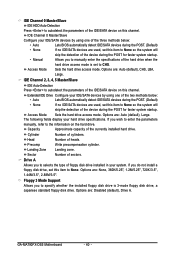
... from the available devices. GA-MA790FX-DS5 Motherboard - 42 - Password Check Specifies whether a password is required for booting the system and for entering the BIOS Setup program. (Default) System A password is required every time the system boots, or only when you enter BIOS Setup. Setup A password ...partitions. Use the up or down arrow key to select a device and press to run multiple operating systems and applications in the BIOS Main Menu. With virtualization, one computer system can function as multiple virtual systems. (Default: Disabled) AMD K8 Cool&Quiet control...
... from the available devices. GA-MA790FX-DS5 Motherboard - 42 - Password Check Specifies whether a password is required for booting the system and for entering the BIOS Setup program. (Default) System A password is required every time the system boots, or only when you enter BIOS Setup. Setup A password ...partitions. Use the up or down arrow key to select a device and press to run multiple operating systems and applications in the BIOS Main Menu. With virtualization, one computer system can function as multiple virtual systems. (Default: Disabled) AMD K8 Cool&Quiet control...
Manual
Page 43
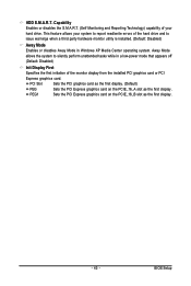
... Sets the PCI graphics card as the first display. (Default) PEG Sets the PCI Express graphics card on the PCIE_16_B slot as the first display. BIOS Setup Capability Enables or disables the S.M.A.R.T. (Self Monitoring and Reporting Technology) capability of the hard drive and to silently perform unattended tasks while in Windows...
... Sets the PCI graphics card as the first display. (Default) PEG Sets the PCI Express graphics card on the PCIE_16_B slot as the first display. BIOS Setup Capability Enables or disables the S.M.A.R.T. (Self Monitoring and Reporting Technology) capability of the hard drive and to silently perform unattended tasks while in Windows...


