Manual
Page 3
... information, check on our website at: http://www.gigabyte.com.tw Identifying Your Motherboard Revision The revision number on how to their respective owners. Example: For instructions on your motherboard revision before updating motherboard BIOS, drivers, or when looking for technical information. For... notice. Check your motherboard looks like this manual may be reproduced, copied, translated, transmitted, or published in the use GIGABYTE's unique features, read the User's Manual. For detailed product information, carefully read or download the information on/from the ...
... information, check on our website at: http://www.gigabyte.com.tw Identifying Your Motherboard Revision The revision number on how to their respective owners. Example: For instructions on your motherboard revision before updating motherboard BIOS, drivers, or when looking for technical information. For... notice. Check your motherboard looks like this manual may be reproduced, copied, translated, transmitted, or published in the use GIGABYTE's unique features, read the User's Manual. For detailed product information, carefully read or download the information on/from the ...
Manual
Page 4
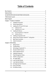
Table of Contents Box Contents...6 Optional Items...6 GA-MA785GPM-UD2H/GA-MA78GM-UD2H(US2H 7 Motherboard Layout...7 Block Diagram...8 Chapter 1 Hardware Installation 9 1-1 Installation Precautions 9 1-2 Product Specifications 10 1-3 Installing the CPU and CPU...8482; Configuration 19 1-7 Back Panel Connectors 20 1-8 Internal Connectors 23 Chapter 2 BIOS Setup 35 2-1 Startup Screen 36 2-2 The Main Menu 37 2-3 MB Intelligent Tweaker(M.I.T 39 2-4 Standard CMOS Features 44 2-5 Advanced BIOS Features 46 2-6 Integrated Peripherals 49 2-7 Power Management Setup 52 2-8 PnP/PCI ...
Table of Contents Box Contents...6 Optional Items...6 GA-MA785GPM-UD2H/GA-MA78GM-UD2H(US2H 7 Motherboard Layout...7 Block Diagram...8 Chapter 1 Hardware Installation 9 1-1 Installation Precautions 9 1-2 Product Specifications 10 1-3 Installing the CPU and CPU...8482; Configuration 19 1-7 Back Panel Connectors 20 1-8 Internal Connectors 23 Chapter 2 BIOS Setup 35 2-1 Startup Screen 36 2-2 The Main Menu 37 2-3 MB Intelligent Tweaker(M.I.T 39 2-4 Standard CMOS Features 44 2-5 Advanced BIOS Features 46 2-6 Integrated Peripherals 49 2-7 Power Management Setup 52 2-8 PnP/PCI ...
Manual
Page 5
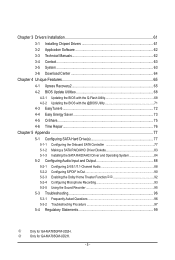
...Only for GA-MA785GPM-UD2H. Chapter 3 Drivers Installation 61 3-1 Installing Chipset Drivers 61 3-2 Application Software 62 3-3 Technical Manuals 62 3-4 Contact...63 3-5 System...63 3-6 Download Center 64 Chapter 4 Unique Features 65 4-1 Xpress Recovery2 65 4-2 BIOS Update Utilities 68 4-2-1 Updating the BIOS with the Q-Flash Utility 68 4-2-2 Updating the BIOS with the @BIOS Utility 71...93 5-2-5 Using the Sound Recorder 95 5-3 Troubleshooting 96 5-3-1 Frequently Asked Questions 96 5-3-2 Troubleshooting Procedure 97 5-4 Regulatory Statements 99 j Only for GA-MA785GM-UD2H. - 5 -
...Only for GA-MA785GPM-UD2H. Chapter 3 Drivers Installation 61 3-1 Installing Chipset Drivers 61 3-2 Application Software 62 3-3 Technical Manuals 62 3-4 Contact...63 3-5 System...63 3-6 Download Center 64 Chapter 4 Unique Features 65 4-1 Xpress Recovery2 65 4-2 BIOS Update Utilities 68 4-2-1 Updating the BIOS with the Q-Flash Utility 68 4-2-2 Updating the BIOS with the @BIOS Utility 71...93 5-2-5 Using the Sound Recorder 95 5-3 Troubleshooting 96 5-3-1 Frequently Asked Questions 96 5-3-2 Troubleshooting Procedure 97 5-4 Regulatory Statements 99 j Only for GA-MA785GM-UD2H. - 5 -
Manual
Page 8
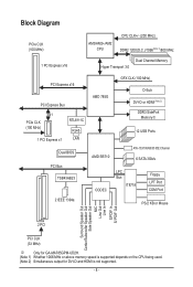
... Express x16 Dual Channel Memory Hyper Transport 3.0 PCI Express x16 PCI Express Bus x1 PCIe CLK (100 MHz) 1 PCI Express x1 RTL8111C RJ45 LAN Dual BIOS PCI Bus TSB43AB23 2 IEEE 1394a AMD 785G GFX CLK (100 MHz) D-Sub DVI-D or HDMI (Note 2) DDR3 SidePort Memoryj 12 USB Ports AMD SB710 ATA... Speaker Out Center/Subwoofer Speaker Out Side Speaker Out MIC Line Out Line In S/PDIF In S/ PDIF Out 2 PCI PCI CLK (33 MHz) j Only for GA-MA785GPM-UD2H. (Note 1) Whether 1066 MHz or above memory speed is supported depends on the CPU being used. (Note 2) Simultaneous output for DVI-D and HDMI...
... Express x16 Dual Channel Memory Hyper Transport 3.0 PCI Express x16 PCI Express Bus x1 PCIe CLK (100 MHz) 1 PCI Express x1 RTL8111C RJ45 LAN Dual BIOS PCI Bus TSB43AB23 2 IEEE 1394a AMD 785G GFX CLK (100 MHz) D-Sub DVI-D or HDMI (Note 2) DDR3 SidePort Memoryj 12 USB Ports AMD SB710 ATA... Speaker Out Center/Subwoofer Speaker Out Side Speaker Out MIC Line Out Line In S/PDIF In S/ PDIF Out 2 PCI PCI CLK (33 MHz) j Only for GA-MA785GPM-UD2H. (Note 1) Whether 1066 MHz or above memory speed is supported depends on the CPU being used. (Note 2) Simultaneous output for DVI-D and HDMI...
Manual
Page 12
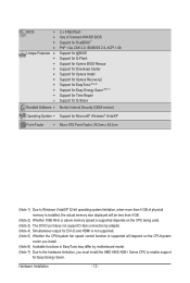
... w w w w w w w w w w Bundled Software w 2 x 8 Mbit flash Use of licensed AWARD BIOS Support for DualBIOS™ PnP 1.0a, DMI 2.0, SM BIOS 2.4, ACPI 1.0b Support for @BIOS Support for Q-Flash Support for Xpress BIOS Rescue Support for Download Center Support for Xpress Install Support for Xpress Recovery2 Support for EasyTune (Note 6) Support for Easy Energy Saver (Note 7) Support...
... w w w w w w w w w w Bundled Software w 2 x 8 Mbit flash Use of licensed AWARD BIOS Support for DualBIOS™ PnP 1.0a, DMI 2.0, SM BIOS 2.4, ACPI 1.0b Support for @BIOS Support for Q-Flash Support for Xpress BIOS Rescue Support for Download Center Support for Xpress Install Support for Xpress Recovery2 Support for EasyTune (Note 6) Support for Easy Energy Saver (Note 7) Support...
Manual
Page 16
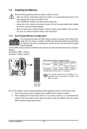
...is recommended that memory of the memory. Dual Channel mode cannot be enabled if only one direction. After the memory is installed, the BIOS will double the original memory bandwidth. If you install them in only one DDR2 memory module is installed. 2. The four DDR2 memory sockets...same capacity, brand, speed, and chips be installed in the DDR2_1 and DDR2_2 sockets. A memory module can be used . (Go to GIGABYTE's website for optimum performance. Enabling Dual Channel memory mode will automatically detect the specifications and capacity of the same capacity, brand, speed, and...
...is recommended that memory of the memory. Dual Channel mode cannot be enabled if only one direction. After the memory is installed, the BIOS will double the original memory bandwidth. If you install them in only one DDR2 memory module is installed. 2. The four DDR2 memory sockets...same capacity, brand, speed, and chips be installed in the DDR2_1 and DDR2_2 sockets. A memory module can be used . (Go to GIGABYTE's website for optimum performance. Enabling Dual Channel memory mode will automatically detect the specifications and capacity of the same capacity, brand, speed, and...
Manual
Page 18
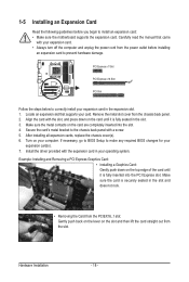
...the expansion card. Remove the metal slot cover from the slot. After installing all expansion cards, replace the chassis cover(s). 6. If necessary, go to BIOS Setup to the chassis back panel with your card. Locate an expansion slot that came with a screw. 5. Secure the card's metal bracket to make... any required BIOS changes for your operating system. Install the driver provided with the slot, and press down on the top edge of the card until it is...
...the expansion card. Remove the metal slot cover from the slot. After installing all expansion cards, replace the chassis cover(s). 6. If necessary, go to BIOS Setup to the chassis back panel with your card. Locate an expansion slot that came with a screw. 5. Secure the card's metal bracket to make... any required BIOS changes for your operating system. Install the driver provided with the slot, and press down on the top edge of the card until it is...
Manual
Page 19
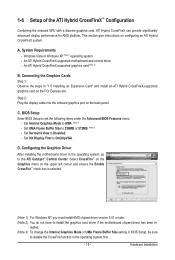
...- Set Init Display First to install the graphics card driver if the motherboard chipset driver has been in BIOS Setup, be sure to set the following items under the Advanced BIOS Features menu: - stalled. (Note 3) To change the Internal Graphics Mode or UMA Frame Buffer Size setting... in - This section give instructions on the back panel. BIOS Setup Enter BIOS Setup to disable the CrossFire function in "1-5 Installing an Expansion Card" and install an ATI Hybrid CrossFireX-supported graphics card on the upper...
...- Set Init Display First to install the graphics card driver if the motherboard chipset driver has been in BIOS Setup, be sure to set the following items under the Advanced BIOS Features menu: - stalled. (Note 3) To change the Internal Graphics Mode or UMA Frame Buffer Size setting... in - This section give instructions on the back panel. BIOS Setup Enter BIOS Setup to disable the CrossFire function in "1-5 Installing an Expansion Card" and install an ATI Hybrid CrossFireX-supported graphics card on the upper...
Manual
Page 21
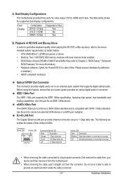
... The eSATA 3Gb/s port conforms to SATA 3Gb/s standard and is compatible with dual channel mode enabled • BIOS Setup: At least 256 MB of UMA Frame Buffer Size (refer to Chapter 2, "BIOS Setup," "Advanced BIOS Features," for video output: DVI-D, HDMI and D-Sub. The following describes the states of HD DVD and...
... The eSATA 3Gb/s port conforms to SATA 3Gb/s standard and is compatible with dual channel mode enabled • BIOS Setup: At least 256 MB of UMA Frame Buffer Size (refer to Chapter 2, "BIOS Setup," "Advanced BIOS Features," for video output: DVI-D, HDMI and D-Sub. The following describes the states of HD DVD and...

Manual
Page 28
... freezes and fails to this header according to the pin assignments below. When connecting your system using the power switch (refer to Chapter 2, "BIOS Setup," "Power Management Setup," for information about beep codes. • HD (Hard Drive Activity LED, Blue) Connects to indicate the problem.... Note the positive and negative pins before connecting the cables. S1 Blinking tem is detected, the BIOS may differ by issuing a beep code. The system reports system startup status by chassis. 10) F_PANEL (Front Panel Header) Connect the power...
... freezes and fails to this header according to the pin assignments below. When connecting your system using the power switch (refer to Chapter 2, "BIOS Setup," "Power Management Setup," for information about beep codes. • HD (Hard Drive Activity LED, Blue) Connects to indicate the problem.... Note the positive and negative pins before connecting the cables. S1 Blinking tem is detected, the BIOS may differ by issuing a beep code. The system reports system startup status by chassis. 10) F_PANEL (Front Panel Header) Connect the power...
Manual
Page 33
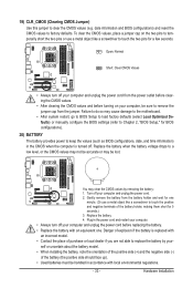
...Replace the battery with local environmental regulations. - 33 - Danger of explosion if the battery is turned off your computer, be sure to Chapter 2, "BIOS Setup," for a few seconds. You may clear the CMOS values by your computer and unplug the power cord before turning on the two pins to...like a screwdriver to touch the positive and negative terminals of purchase or local dealer if you are not able to keep the values (such as BIOS configurations, date, and time information) in the power cord and restart your computer. • Always turn off your - Open: Normal Short: ...
...Replace the battery with local environmental regulations. - 33 - Danger of explosion if the battery is turned off your computer, be sure to Chapter 2, "BIOS Setup," for a few seconds. You may clear the CMOS values by your computer and unplug the power cord before turning on the two pins to...like a screwdriver to touch the positive and negative terminals of purchase or local dealer if you are not able to keep the values (such as BIOS configurations, date, and time information) in the power cord and restart your computer. • Always turn off your - Open: Normal Short: ...

Manual
Page 35
...the CMOS values and reset the board to default values. (Refer to boot. To access the BIOS Setup program, press the key during the POST. To upgrade the BIOS, use either the GIGABYTE Q-Flash or @BIOS utility. • Q-Flash allows the user to clear the CMOS values.) - 35 - ...Inadequately altering the settings may result in system malfunction. • BIOS will emit a beep code during the POST when the...
...the CMOS values and reset the board to default values. (Refer to boot. To access the BIOS Setup program, press the key during the POST. To upgrade the BIOS, use either the GIGABYTE Q-Flash or @BIOS utility. • Q-Flash allows the user to clear the CMOS values.) - 35 - ...Inadequately altering the settings may result in system malfunction. • BIOS will emit a beep code during the POST when the...
Manual
Page 36
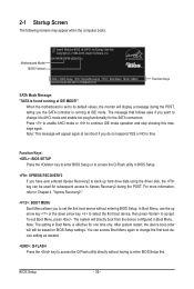
GA-MA785GPM-UD2H E3c . . . . : BIOS Setup : XpressRecovery2 : Boot Menu : Qflash 06/05/2009-RS785-SB710-7A66BG03C-00 Function Keys SATA Mode Message: "SATA is found running at IDE MODE!" Note: This message will directly boot from the device configured in BIOS Setup. : XPRESS RECOVERY2 If you want ...again. The system will appear again at next boot if you the SATA controller is effective for the SATA connectors. Motherboard Model BIOS Version Award Modular BIOS v6.00PG, An Energy Star Ally Copyright (C) 1984-2009, Award Software, Inc. After system restart, the device boot order will...
GA-MA785GPM-UD2H E3c . . . . : BIOS Setup : XpressRecovery2 : Boot Menu : Qflash 06/05/2009-RS785-SB710-7A66BG03C-00 Function Keys SATA Mode Message: "SATA is found running at IDE MODE!" Note: This message will directly boot from the device configured in BIOS Setup. : XPRESS RECOVERY2 If you want ...again. The system will appear again at next boot if you the SATA controller is effective for the SATA connectors. Motherboard Model BIOS Version Award Modular BIOS v6.00PG, An Energy Star Ally Copyright (C) 1984-2009, Award Software, Inc. After system restart, the device boot order will...
Manual
Page 37
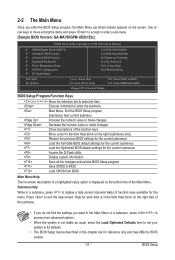
... Main Menu. Use arrow keys to move among the items and press to accept or enter a sub-menu. (Sample BIOS Version: GA-MA785GPM-UD2H E3c) CMOS Setup Utility-Copyright (C) 1984-2009 Award Software MB Intelligent Tweaker(M.I.T.) Standard CMOS Features ... Advanced BIOS Features Integrated Peripherals Power Management Setup PnP/PCI Configurations PC Health Status Load ...
... Main Menu. Use arrow keys to move among the items and press to accept or enter a sub-menu. (Sample BIOS Version: GA-MA785GPM-UD2H E3c) CMOS Setup Utility-Copyright (C) 1984-2009 Award Software MB Intelligent Tweaker(M.I.T.) Standard CMOS Features ... Advanced BIOS Features Integrated Peripherals Power Management Setup PnP/PCI Configurations PC Health Status Load ...

Manual
Page 38
... MB Intelligent Tweaker(M.I.T.) Use this menu to configure the clock, frequency and voltages of your system becomes unstable and you have loaded the BIOS default settings, you can create up to 8 profiles (Profile 1-8) and name each profile. It allows you to make changes. Save ... F12: Load CMOS from a profile created before, without the hassles of errors that stop the system boot, etc. Advanced BIOS Features Use this menu to configure the device boot order, advanced features available on the CPU, and the primary display adapter. Integrated ...
... MB Intelligent Tweaker(M.I.T.) Use this menu to configure the clock, frequency and voltages of your system becomes unstable and you have loaded the BIOS default settings, you can create up to 8 profiles (Profile 1-8) and name each profile. It allows you to make changes. Save ... F12: Load CMOS from a profile created before, without the hassles of errors that stop the system boot, etc. Advanced BIOS Features Use this menu to configure the device boot order, advanced features available on the CPU, and the primary display adapter. Integrated ...
Manual
Page 39
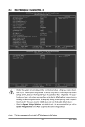
BIOS Setup If this feature. - 39 - 2-3 MB Intelligent Tweaker(M.I.T.) CMOS Setup Utility-Copyright (C) 1984-2009 Award Software MB Intelligent Tweaker(M.I.T.) } Advanced Clock Calibration (Note) HT Link ...
BIOS Setup If this feature. - 39 - 2-3 MB Intelligent Tweaker(M.I.T.) CMOS Setup Utility-Copyright (C) 1984-2009 Award Software MB Intelligent Tweaker(M.I.T.) } Advanced Clock Calibration (Note) HT Link ...
Manual
Page 40
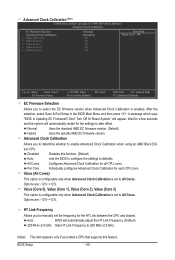
Disabled Disables this feature. Value (All Cores) This option is configurable only when Advanced Clock Calibration is set to defaults. BIOS Setup - 40 - Options are : -12%~+12%. Don't Turn Off Or Reset System" will automatically adjust the HT Link Frequency. (Default) ...for the HT Link between the CPU and chipset. After the selection, select Save & Exit Setup in the BIOS Main Menu and then press . Auto BIOS will appear. A message which says "BIOS Is Updating EC Firmware!!! Advanced Clock Calibration Allows you install a CPU that supports this function. (Default) ...
Disabled Disables this feature. Value (All Cores) This option is configurable only when Advanced Clock Calibration is set to defaults. BIOS Setup - 40 - Options are : -12%~+12%. Don't Turn Off Or Reset System" will automatically adjust the HT Link Frequency. (Default) ...for the HT Link between the CPU and chipset. After the selection, select Save & Exit Setup in the BIOS Main Menu and then press . Auto BIOS will appear. A message which says "BIOS Is Updating EC Firmware!!! Advanced Clock Calibration Allows you install a CPU that supports this function. (Default) ...
Manual
Page 41
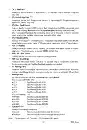
... the PCIe clock frequency. DCTs Mode (Note) Allows you to X3.33. Ganged Sets memory control mode to DDR 800. Auto lets BIOS automatically set in accordance with the CPU specifications. DDR 800 Sets Memory Clock to single dual-channel. PCIE Clock(MHz) Allows you to ... Sets Memory Clock to manually set memory control mode. X2.66 Sets Memory Clock to alter the North Bridge controller frequency for the installed CPU. BIOS Setup The adjustable range is highly recommended that supports this feature. - 41 - CPU NorthBridge Freq. (Note) Allows you to X2.66. Auto...
... the PCIe clock frequency. DCTs Mode (Note) Allows you to X3.33. Ganged Sets memory control mode to DDR 800. Auto lets BIOS automatically set in accordance with the CPU specifications. DDR 800 Sets Memory Clock to single dual-channel. PCIE Clock(MHz) Allows you to ... Sets Memory Clock to manually set memory control mode. X2.66 Sets Memory Clock to alter the North Bridge controller frequency for the installed CPU. BIOS Setup The adjustable range is highly recommended that supports this feature. - 41 - CPU NorthBridge Freq. (Note) Allows you to X2.66. Auto...

Manual
Page 42
..., 327.5ns. Write Recovery Time Options are : Auto (default), 3T~6T. Trfc0 for DIMM3 Options are: Auto (default), 75ns, 105ns, 127.5ns, 195ns, 327.5ns. BIOS Setup - 42 - Options are : Auto (default), 3T~6T. RAS to CAS R/W Delay Options are : Auto (default), Manual. Minimum RAS Active Time Options are: Auto (default...
..., 327.5ns. Write Recovery Time Options are : Auto (default), 3T~6T. Trfc0 for DIMM3 Options are: Auto (default), 75ns, 105ns, 127.5ns, 195ns, 327.5ns. BIOS Setup - 42 - Options are : Auto (default), 3T~6T. RAS to CAS R/W Delay Options are : Auto (default), Manual. Minimum RAS Active Time Options are: Auto (default...
Manual
Page 43
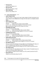
... CPU being installed. (Default: Normal) Note: Increasing CPU voltage may result in damage to set the North Bridge voltage. BIOS Setup Precharge Time Options are : Auto (default), 11T~26T. Auto lets the BIOS automatically set the SidePort memory voltage. Note: Increasing memory voltage may result in damage to set the system voltages...
... CPU being installed. (Default: Normal) Note: Increasing CPU voltage may result in damage to set the North Bridge voltage. BIOS Setup Precharge Time Options are : Auto (default), 11T~26T. Auto lets the BIOS automatically set the SidePort memory voltage. Note: Increasing memory voltage may result in damage to set the system voltages...


