Manual
Page 3
... instructions on your motherboard revision before updating motherboard BIOS, drivers, or when looking for technical information. For example, "REV: 1.0" means the revision of this : "REV: X.X." Copyright © 2009 GIGA-BYTE TECHNOLOGY CO., LTD. Disclaimer Information in this product, GIGABYTE provides the following types of documentations: For quick set-up of GIGABYTE. No part of the motherboard is the property of the product, read the User's Manual...
... instructions on your motherboard revision before updating motherboard BIOS, drivers, or when looking for technical information. For example, "REV: 1.0" means the revision of this : "REV: X.X." Copyright © 2009 GIGA-BYTE TECHNOLOGY CO., LTD. Disclaimer Information in this product, GIGABYTE provides the following types of documentations: For quick set-up of GIGABYTE. No part of the motherboard is the property of the product, read the User's Manual...
Manual
Page 4
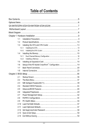
.../GA-MA78GM-UD2H(US2H 7 Motherboard Layout...7 Block Diagram...8 Chapter 1 Hardware Installation 9 1-1 Installation Precautions 9 1-2 Product Specifications 10 1-3 Installing the CPU and CPU Cooler 13 1-3-1 Installing the CPU 13 1-3-2 Installing the CPU Cooler 15 1-4 Installing the Memory 16 1-4-1 Dual Channel Memory Configuration 16 1-4-2 Installing a Memory 17 1-5 Installing an Expansion Card 18 1-6 Setup of the ATI Hybrid CrossFireX™ Configuration 19 1-7 Back Panel Connectors 20 1-8 Internal Connectors 23 Chapter 2 BIOS Setup 35 2-1 Startup Screen 36 2-2 The Main Menu...
.../GA-MA78GM-UD2H(US2H 7 Motherboard Layout...7 Block Diagram...8 Chapter 1 Hardware Installation 9 1-1 Installation Precautions 9 1-2 Product Specifications 10 1-3 Installing the CPU and CPU Cooler 13 1-3-1 Installing the CPU 13 1-3-2 Installing the CPU Cooler 15 1-4 Installing the Memory 16 1-4-1 Dual Channel Memory Configuration 16 1-4-2 Installing a Memory 17 1-5 Installing an Expansion Card 18 1-6 Setup of the ATI Hybrid CrossFireX™ Configuration 19 1-7 Back Panel Connectors 20 1-8 Internal Connectors 23 Chapter 2 BIOS Setup 35 2-1 Startup Screen 36 2-2 The Main Menu...
Manual
Page 5
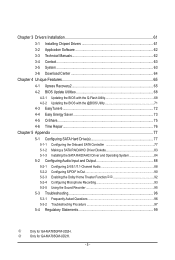
... with the @BIOS Utility 71 4-3 EasyTune 6...72 4-4 Easy Energy Saver 73 4-5 Q-Share...75 4-6 Time Repair...76 Chapter 5 Appendix...77 5-1 Configuring SATA Hard Drive(s 77 5-1-1 Configuring the Onboard SATA Controller 77 5-1-2 Making a SATA RAID/AHCI Driver Diskette 83 5-1-3 Installing the SATA RAID/AHCI Driver and Operating System 84 5-2 Configuring Audio Input and Output 88 5-2-1 Configuring 2/4/5.1/7.1-Channel Audio 88 5-2-2 Configuring S/PDIF In/Out 90 5-2-3 Enabling the Dolby Home Theater Functionjk 92 5-2-4 Configuring Microphone Recording 93 5-2-5 Using the Sound Recorder 95...
... with the @BIOS Utility 71 4-3 EasyTune 6...72 4-4 Easy Energy Saver 73 4-5 Q-Share...75 4-6 Time Repair...76 Chapter 5 Appendix...77 5-1 Configuring SATA Hard Drive(s 77 5-1-1 Configuring the Onboard SATA Controller 77 5-1-2 Making a SATA RAID/AHCI Driver Diskette 83 5-1-3 Installing the SATA RAID/AHCI Driver and Operating System 84 5-2 Configuring Audio Input and Output 88 5-2-1 Configuring 2/4/5.1/7.1-Channel Audio 88 5-2-2 Configuring S/PDIF In/Out 90 5-2-3 Enabling the Dolby Home Theater Functionjk 92 5-2-4 Configuring Microphone Recording 93 5-2-5 Using the Sound Recorder 95...
Manual
Page 10
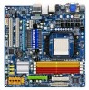
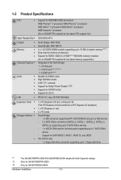
... latest memory support list.) Integrated in the North Bridge: - 1 x D-Sub port - 1 x DVI-D port (Note 3) (Note 4) - 1 x HDMI port (Note 4) Realtek ALC889A codec High Definition Audio 2/4/5.1/7.1-channel Support for Dolby® Home Theater jk Support for S/PDIF In/Out Support for CD In LAN RTL8111C chip (10/100/1000 Mbit) Expansion Slots 1 x PCI Express x16 slot, running at x16 (The PCI Express x16 slot conforms to PCI Express 2.0 standard 1 x PCI Express x1 slot 2 x PCI slots Storage Interface South Bridge: - 1 x IDE connector supporting...
... latest memory support list.) Integrated in the North Bridge: - 1 x D-Sub port - 1 x DVI-D port (Note 3) (Note 4) - 1 x HDMI port (Note 4) Realtek ALC889A codec High Definition Audio 2/4/5.1/7.1-channel Support for Dolby® Home Theater jk Support for S/PDIF In/Out Support for CD In LAN RTL8111C chip (10/100/1000 Mbit) Expansion Slots 1 x PCI Express x16 slot, running at x16 (The PCI Express x16 slot conforms to PCI Express 2.0 standard 1 x PCI Express x1 slot 2 x PCI slots Storage Interface South Bridge: - 1 x IDE connector supporting...
Manual
Page 18
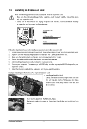
.... Remove the metal slot cover from the power outlet before you begin to install an expansion card: • Make sure the motherboard supports the expansion card. Install the driver provided with your operating system. After installing all expansion cards, replace the chassis cover(s). 6. Carefully read the manual that supports your computer. PCI Express x1 Slot PCI Express x16 Slot PCI Slot Follow the steps below to make any required BIOS changes for your expansion card in the slot...
.... Remove the metal slot cover from the power outlet before you begin to install an expansion card: • Make sure the motherboard supports the expansion card. Install the driver provided with your operating system. After installing all expansion cards, replace the chassis cover(s). 6. Carefully read the manual that supports your computer. PCI Express x1 Slot PCI Express x16 Slot PCI Slot Follow the steps below to make any required BIOS changes for your expansion card in the slot...
Manual
Page 19
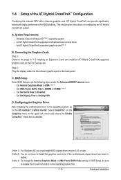
.... BIOS Setup Enter BIOS Setup to disable the CrossFire function in BIOS Setup, be sure to set the following items under the Advanced BIOS Features menu: - 1-6 Setup of the ATI Hybrid CrossFireX™ Configuration Combining the onboard GPU with a discrete graphics card, ATI Hybrid CrossFireX can provide significantly advanced display performance for AMD platform. A. Step 2: Plug the display cable into the onboard graphics port on configuring an ATI Hybrid CrossFireX system. stalled. (Note 3) To change the Internal Graphics Mode...
.... BIOS Setup Enter BIOS Setup to disable the CrossFire function in BIOS Setup, be sure to set the following items under the Advanced BIOS Features menu: - 1-6 Setup of the ATI Hybrid CrossFireX™ Configuration Combining the onboard GPU with a discrete graphics card, ATI Hybrid CrossFireX can provide significantly advanced display performance for AMD platform. A. Step 2: Plug the display cable into the onboard graphics port on configuring an ATI Hybrid CrossFireX system. stalled. (Note 3) To change the Internal Graphics Mode...
Manual
Page 21
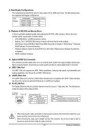
... 800 memory modules with SATA 1.5Gb/s standard. IEEE 1394a Port The IEEE 1394 port supports the IEEE 1394a specification, featuring high speed, high bandwidth and hotplug capabilities. eSATA 3Gb/s Port The eSATA 3Gb/s port conforms to SATA 3Gb/s standard and is compatible with dual channel mode enabled • BIOS Setup: At least 256 MB of UMA Frame Buffer Size (refer to Chapter 2, "BIOS Setup," "Advanced BIOS Features," for video output: DVI-D, HDMI and D-Sub. Connection/ Speed LED Activity LED LAN Port Connection/Speed LED...
... 800 memory modules with SATA 1.5Gb/s standard. IEEE 1394a Port The IEEE 1394 port supports the IEEE 1394a specification, featuring high speed, high bandwidth and hotplug capabilities. eSATA 3Gb/s Port The eSATA 3Gb/s port conforms to SATA 3Gb/s standard and is compatible with dual channel mode enabled • BIOS Setup: At least 256 MB of UMA Frame Buffer Size (refer to Chapter 2, "BIOS Setup," "Advanced BIOS Features," for video output: DVI-D, HDMI and D-Sub. Connection/ Speed LED Activity LED LAN Port Connection/Speed LED...

Manual
Page 25
... the chassis. Pin No. Overheating may hang. • These fan headers are not configuration jumper blocks. 3/4) CPU_FAN/SYS_FAN (Fan Headers) The motherboard has a 4-pin CPU fan header (CPU_FAN)and a 4-pin system fan header(SYS_FAN). Hardware Installation Most fans are designed with color-coded power connector wires. Each fan header supplies a +12V power voltage and possesses a foolproof insertion design. Most fans are designed with colorcoded power connector wires. The motherboard supports CPU fan speed control, which requires the use of a CPU fan with fan speed control...
... the chassis. Pin No. Overheating may hang. • These fan headers are not configuration jumper blocks. 3/4) CPU_FAN/SYS_FAN (Fan Headers) The motherboard has a 4-pin CPU fan header (CPU_FAN)and a 4-pin system fan header(SYS_FAN). Hardware Installation Most fans are designed with color-coded power connector wires. Each fan header supplies a +12V power voltage and possesses a foolproof insertion design. Most fans are designed with colorcoded power connector wires. The motherboard supports CPU fan speed control, which requires the use of a CPU fan with fan speed control...
Manual
Page 33
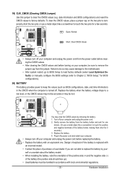
... - Replace the battery. 4. self or uncertain about the battery model. • When installing the battery, note the orientation of the positive side (+) and the negative side (-) of the battery (the positive side should face up). • Used batteries must be accurate or may cause damage to the motherboard. • After system restart, go to BIOS Setup to load factory defaults (select Load Optimized Defaults) or manually configure the BIOS settings...
... - Replace the battery. 4. self or uncertain about the battery model. • When installing the battery, note the orientation of the positive side (+) and the negative side (-) of the battery (the positive side should face up). • Used batteries must be accurate or may cause damage to the motherboard. • After system restart, go to BIOS Setup to load factory defaults (select Load Optimized Defaults) or manually configure the BIOS settings...
Manual
Page 36
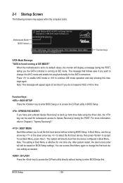
... display a message during the POST. Press to enable AHCI mode or to AHCI mode and enable hot plug functionality for the SATA connectors. For more information, refer to Chapter 4, "Xpress Recovery2." : BOOT MENU Boot Menu allows you want to change the first boot device setting as needed. : Q-FLASH Press the key to Xpress Recovery2 during the POST, telling you do not respond YES or NO in Boot Menu. You can be based on BIOS Setup settings. Motherboard Model BIOS Version Award Modular BIOS...
... display a message during the POST. Press to enable AHCI mode or to AHCI mode and enable hot plug functionality for the SATA connectors. For more information, refer to Chapter 4, "Xpress Recovery2." : BOOT MENU Boot Menu allows you want to change the first boot device setting as needed. : Q-FLASH Press the key to Xpress Recovery2 during the POST, telling you do not respond YES or NO in Boot Menu. You can be based on BIOS Setup settings. Motherboard Model BIOS Version Award Modular BIOS...

Manual
Page 38
... key) and then press to complete. F12: Load CMOS from a profile created before, without the hassles of errors that stop the system boot, etc. Advanced BIOS Features Use this menu to configure the device boot order, advanced features available on the CPU, and the primary display adapter. Integrated Peripherals Use this menu to configure all peripheral devices, such as IDE, SATA, USB, integrated audio, and integrated LAN, etc. Power...
... key) and then press to complete. F12: Load CMOS from a profile created before, without the hassles of errors that stop the system boot, etc. Advanced BIOS Features Use this menu to configure the device boot order, advanced features available on the CPU, and the primary display adapter. Integrated Peripherals Use this menu to configure all peripheral devices, such as IDE, SATA, USB, integrated audio, and integrated LAN, etc. Power...
Manual
Page 46
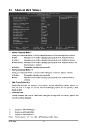
... an ATI graphics card is the total amount of system memory allocated solely for GA-MA785GM-UD2H. Only for the onboard graphics controller. 2-5 Advanced BIOS Features CMOS Setup Utility-Copyright (C) 1984-2009 Award Software Advanced BIOS Features Internal Graphics Mode j Internal Graphics Mode kl UMA Frame Buffer Size x Surround View Onboard VGA output connect AMD C1E Support (Note) Virtualization Patch AMD TLB Erratum (Note) AMD K8 Cool&Quiet control } Hard Disk Boot Priority First Boot Device Second Boot Device Third Boot Device Password Check HDD...
... an ATI graphics card is the total amount of system memory allocated solely for GA-MA785GM-UD2H. Only for the onboard graphics controller. 2-5 Advanced BIOS Features CMOS Setup Utility-Copyright (C) 1984-2009 Award Software Advanced BIOS Features Internal Graphics Mode j Internal Graphics Mode kl UMA Frame Buffer Size x Surround View Onboard VGA output connect AMD C1E Support (Note) Virtualization Patch AMD TLB Erratum (Note) AMD K8 Cool&Quiet control } Hard Disk Boot Priority First Boot Device Second Boot Device Third Boot Device Password Check HDD...

Manual
Page 47
...: Floppy, LS120, Hard Disk, CDROM, ZIP, USB-FDD, USB-ZIP, USB-CDROM, USB-HDD, Legacy LAN, Disabled. Password Check Specifies whether a password is installed. (Default: Enabled) (Note) This item appears only if you enter BIOS Setup. HDD S.M.A.R.T. Use the up or down arrow key to select a device and press to issue warnings when a third party hardware monitor utility is required every time the system boots, or only when you install a CPU that supports this feature. - 47 - Onboard VGA output connect Specifies the graphics display...
...: Floppy, LS120, Hard Disk, CDROM, ZIP, USB-FDD, USB-ZIP, USB-CDROM, USB-HDD, Legacy LAN, Disabled. Password Check Specifies whether a password is installed. (Default: Enabled) (Note) This item appears only if you enter BIOS Setup. HDD S.M.A.R.T. Use the up or down arrow key to select a device and press to issue warnings when a third party hardware monitor utility is required every time the system boots, or only when you install a CPU that supports this feature. - 47 - Onboard VGA output connect Specifies the graphics display...
Manual
Page 49
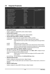
... CMOS Setup Utility-Copyright (C) 1984-2009 Award Software Integrated Peripherals OnChip IDE Channel OnChip SATA Controller OnChip SATA Type x OnChip SATA Port4/5 Type Onboard Audio Function Onboard 1394 Function Onboard LAN Function } SMART LAN Onboard LAN Boot ROM OnChip USB Controller USB EHCI Controller USB Keyboard Support USB Mouse Support Legacy USB storage detect Onboard Serial Port 1 Onboard Parallel Port Parallel Port Mode x ECP Mode Use DMA [Enabled] [Enabled] [Native IDE] IDE [Enabled] [Enabled] [Enabled] [Press Enter] [Disabled...
... CMOS Setup Utility-Copyright (C) 1984-2009 Award Software Integrated Peripherals OnChip IDE Channel OnChip SATA Controller OnChip SATA Type x OnChip SATA Port4/5 Type Onboard Audio Function Onboard 1394 Function Onboard LAN Function } SMART LAN Onboard LAN Boot ROM OnChip USB Controller USB EHCI Controller USB Keyboard Support USB Mouse Support Legacy USB storage detect Onboard Serial Port 1 Onboard Parallel Port Parallel Port Mode x ECP Mode Use DMA [Enabled] [Enabled] [Native IDE] IDE [Enabled] [Enabled] [Enabled] [Press Enter] [Disabled...

Manual
Page 51
.... Options are : SPP (Standard Parallel Port) (default), EPP (Enhanced Parallel Port), ECP (Extended Capabilities Port), ECP+EPP. Onboard LAN Boot ROM Allows you to decide whether to ECP or ECP+EPP mode. USB EHCI Controller Enables or disables the integrated USB 2.0 controller. (Default: Enabled) USB Keyboard Support Allows USB keyboard to be used in MS-DOS. (Default: Enabled) USB Mouse Support Allows USB mouse to detect USB storage devices, including USB flash drives and USB hard drives during the POST. (Default: Enabled) Onboard Serial Port 1 Enables or disables the first serial port and...
.... Options are : SPP (Standard Parallel Port) (default), EPP (Enhanced Parallel Port), ECP (Extended Capabilities Port), ECP+EPP. Onboard LAN Boot ROM Allows you to decide whether to ECP or ECP+EPP mode. USB EHCI Controller Enables or disables the integrated USB 2.0 controller. (Default: Enabled) USB Keyboard Support Allows USB keyboard to be used in MS-DOS. (Default: Enabled) USB Mouse Support Allows USB mouse to detect USB storage devices, including USB flash drives and USB hard drives during the POST. (Default: Enabled) Onboard Serial Port 1 Enables or disables the first serial port and...

Manual
Page 52
... installed USB device. (Default: Enabled) Modem Ring Resume Allows the system to be awakened from a modem that supports wake-up function. (Default: Disabled) (Note) Supported on Suspend) sleep state. 2-7 Power Management Setup CMOS Setup Utility-Copyright (C) 1984-2009 Award Software Power Management Setup ACPI Suspend Type Soft-Off by Power button USB Wake Up from S3 Modem Ring Resume PME Event Wake Up HPET Support (Note) Power On By Mouse Power On By Keyboard x KB Power ON Password AC Back Function Power-On by a wake...
... installed USB device. (Default: Enabled) Modem Ring Resume Allows the system to be awakened from a modem that supports wake-up function. (Default: Disabled) (Note) Supported on Suspend) sleep state. 2-7 Power Management Setup CMOS Setup Utility-Copyright (C) 1984-2009 Award Software Power Management Setup ACPI Suspend Type Soft-Off by Power button USB Wake Up from S3 Modem Ring Resume PME Event Wake Up HPET Support (Note) Power On By Mouse Power On By Keyboard x KB Power ON Password AC Back Function Power-On by a wake...

Manual
Page 77
... cable to the rear of the SATA hard drive and the other end to available SATA port on the SATA controller. (Note 2) Required when the SATA controller is recommended that you do not want to ensure optimal performance, it is set to create RAID array on the motherboard. Make a floppy disk containing the SATA RAID/AHCI driver for Windows XP. (Note 2) E. If you use two hard drives with identical model and capacity). B. Then connect the power connector...
... cable to the rear of the SATA hard drive and the other end to available SATA port on the SATA controller. (Note 2) Required when the SATA controller is recommended that you do not want to ensure optimal performance, it is set to create RAID array on the motherboard. Make a floppy disk containing the SATA RAID/AHCI driver for Windows XP. (Note 2) E. If you use two hard drives with identical model and capacity). B. Then connect the power connector...

Manual
Page 83
... SATA controller from the menu and press . Steps: 1: Boot from the motherboard driver disk to the RAID/ AHCI hard drives, select 3) SB700/710/750 SATA Driver for XP. See the instructions below about how to copy the driver in Figure 3, to install Windows XP to a USB flash drive. Press any key to the floppy disk. Appendix For installing Windows Vista, you wish to \x64 if you also can copy the SATA controller driver from the startup disk. 2: Remove the startup disk...
... SATA controller from the menu and press . Steps: 1: Boot from the motherboard driver disk to the RAID/ AHCI hard drives, select 3) SB700/710/750 SATA Driver for XP. See the instructions below about how to copy the driver in Figure 3, to install Windows XP to a USB flash drive. Press any key to the floppy disk. Appendix For installing Windows Vista, you wish to \x64 if you also can copy the SATA controller driver from the startup disk. 2: Remove the startup disk...
Manual
Page 84
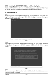
... AMD AHCI Compatible RAID Controller-x64 platform ENTER=Select F3=Exit Step 3: Figure 2 On the next screen, press to install a third party SCSI or RAID driver. 5-1-3 Installing the SATA RAID/AHCI Driver and Operating System With the SATA RAID/AHCI driver diskette and correct BIOS settings, you are examples of Windows XP and Vista installation. A screen will appear. Windows Setup You have chosen to specify additional device. ceed with Windows, using a device support disk provided by an adapter manufacturer. Appendix - 84 - Then a controller menu...
... AMD AHCI Compatible RAID Controller-x64 platform ENTER=Select F3=Exit Step 3: Figure 2 On the next screen, press to install a third party SCSI or RAID driver. 5-1-3 Installing the SATA RAID/AHCI Driver and Operating System With the SATA RAID/AHCI driver diskette and correct BIOS settings, you are examples of Windows XP and Vista installation. A screen will appear. Windows Setup You have chosen to specify additional device. ceed with Windows, using a device support disk provided by an adapter manufacturer. Appendix - 84 - Then a controller menu...
Manual
Page 96
... instructions on GIGABYTE's website. Turn off your computer. Saves changes and exit BIOS Setup (select "Save & Exit Setup") to the maximum volume? Q: Why do the beeps emitted during the POST mean? Q: What do I still get a weak sound even though I clear the CMOS values? A: The following Award BIOS beep code descriptions may help you identify possible computer problems. (For reference only.) 1 short: System boots successfully 2 short: CMOS setting error 1 long, 1 short: Memory or motherboard error 1 long, 2 short: Monitor or graphics card error 1 long, 3 short: Keyboard error 1 long...
... instructions on GIGABYTE's website. Turn off your computer. Saves changes and exit BIOS Setup (select "Save & Exit Setup") to the maximum volume? Q: Why do the beeps emitted during the POST mean? Q: What do I still get a weak sound even though I clear the CMOS values? A: The following Award BIOS beep code descriptions may help you identify possible computer problems. (For reference only.) 1 short: System boots successfully 2 short: CMOS setting error 1 long, 1 short: Memory or motherboard error 1 long, 2 short: Monitor or graphics card error 1 long, 3 short: Keyboard error 1 long...


