Manual
Page 1
GA-MA785GPM-UD2H/ GA-MA785GM-UD2H/ GA-MA785GM-US2H AM2+/AM2 socket motherboard for AMD Phenom™ II processor/ AMD Phenom™ processor/ AMD Athlon™ II processor/ AMD Athlon™ processor/ AMD Sempron™ processor User's Manual Rev. 1001 12ME-MA785M2-1001R
GA-MA785GPM-UD2H/ GA-MA785GM-UD2H/ GA-MA785GM-US2H AM2+/AM2 socket motherboard for AMD Phenom™ II processor/ AMD Phenom™ processor/ AMD Athlon™ II processor/ AMD Athlon™ processor/ AMD Sempron™ processor User's Manual Rev. 1001 12ME-MA785M2-1001R
Manual
Page 3
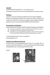
... laws and is 1.0. Example: For product-related information, check on our website at: http://www.gigabyte.com.tw Identifying Your Motherboard Revision The revision number on our website. The trademarks mentioned in this manual are legally registered to ... X.X." Documentation Classifications In order to their respective owners. Check your motherboard looks like this manual is protected by GIGABYTE without GIGABYTE's prior written permission. Disclaimer Information in the use GIGABYTE's unique features, read the User's Manual. For detailed product information...
... laws and is 1.0. Example: For product-related information, check on our website at: http://www.gigabyte.com.tw Identifying Your Motherboard Revision The revision number on our website. The trademarks mentioned in this manual are legally registered to ... X.X." Documentation Classifications In order to their respective owners. Check your motherboard looks like this manual is protected by GIGABYTE without GIGABYTE's prior written permission. Disclaimer Information in the use GIGABYTE's unique features, read the User's Manual. For detailed product information...
Manual
Page 4
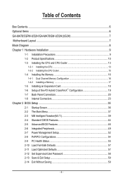
Table of Contents Box Contents...6 Optional Items...6 GA-MA785GPM-UD2H/GA-MA78GM-UD2H(US2H 7 Motherboard Layout...7 Block Diagram...8 Chapter 1 Hardware Installation 9 1-1 Installation Precautions 9 1-2 Product Specifications 10 1-3 Installing the CPU and CPU Cooler 13 1-3-1 Installing the CPU 13 1-3-2 Installing the CPU ...
Table of Contents Box Contents...6 Optional Items...6 GA-MA785GPM-UD2H/GA-MA78GM-UD2H(US2H 7 Motherboard Layout...7 Block Diagram...8 Chapter 1 Hardware Installation 9 1-1 Installation Precautions 9 1-2 Product Specifications 10 1-3 Installing the CPU and CPU Cooler 13 1-3-1 Installing the CPU 13 1-3-2 Installing the CPU ...
Manual
Page 6
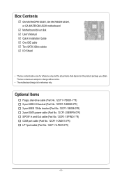
... and Out cable (Part No. 12CR1-1SPINO-1*R) COM port cable (Part No. 12CF1-1CM001-3*R) LPT port cable (Part No. 12CF1-1LP001-0*R) - 6 - Box Contents GA-MA785GPM-UD2H, GA-MA785GM-UD2H, or GA-MA785GM-US2H motherboard Motherboard driver disk User's Manual Quick Installation Guide One IDE cable Two SATA 3Gb/s cables I/O Shield • The box contents above are subject to...
... and Out cable (Part No. 12CR1-1SPINO-1*R) COM port cable (Part No. 12CF1-1CM001-3*R) LPT port cable (Part No. 12CF1-1LP001-0*R) - 6 - Box Contents GA-MA785GPM-UD2H, GA-MA785GM-UD2H, or GA-MA785GM-US2H motherboard Motherboard driver disk User's Manual Quick Installation Guide One IDE cable Two SATA 3Gb/s cables I/O Shield • The box contents above are subject to...
Manual
Page 7
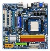
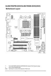
... connect a PS/2 keyboard or PS/2 mouse. - 7 - Only for GA-MA785GPM-UD2H. GA-MA785GPM-UD2H/GA-MA785GM-UD2H(US2H) Motherboard Layout DVI VGA KB(Note)_USB ATX_12V_2X4 Socket AM2 M_BIOS B_BIOS CI IT8718 ATX HDMI USB ESATA 1394 OPTICAL CPU_FAN FDD USB LAN AUDIO F_AUDIO PCIEX1 GA-MA785GPM-UD2H/ GA-MA785GM-UD2H/ GA-MA785GM-US2H AMD 785G SidePort Memoryj NB_FAN RTL8111C PCI1 CD_IN...
... connect a PS/2 keyboard or PS/2 mouse. - 7 - Only for GA-MA785GPM-UD2H. GA-MA785GPM-UD2H/GA-MA785GM-UD2H(US2H) Motherboard Layout DVI VGA KB(Note)_USB ATX_12V_2X4 Socket AM2 M_BIOS B_BIOS CI IT8718 ATX HDMI USB ESATA 1394 OPTICAL CPU_FAN FDD USB LAN AUDIO F_AUDIO PCIEX1 GA-MA785GPM-UD2H/ GA-MA785GM-UD2H/ GA-MA785GM-US2H AMD 785G SidePort Memoryj NB_FAN RTL8111C PCI1 CD_IN...
Manual
Page 9
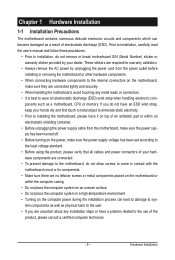
...power supply has been turned off. • Before turning on the computer power during the installation process can become damaged as a motherboard, CPU or memory. Hardware Installation These stickers are required for warranty validation. • Always remove the AC power by your hands...of electrostatic discharge (ESD). ponents such as a result of your hardware components are connected tightly and securely. • When handling the motherboard, avoid touching any installation steps or have it on top of an antistatic pad or within an electrostatic shielding container. • Before...
...power supply has been turned off. • Before turning on the computer power during the installation process can become damaged as a motherboard, CPU or memory. Hardware Installation These stickers are required for warranty validation. • Always remove the AC power by your hands...of electrostatic discharge (ESD). ponents such as a result of your hardware components are connected tightly and securely. • When handling the motherboard, avoid touching any installation steps or have it on top of an antistatic pad or within an electrostatic shielding container. • Before...
Manual
Page 12
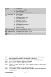
... CPU/system fan speed control function is supported will depend on the CPU/system cooler you install. (Note 6) Available functions in EasyTune may differ by motherboard model. (Note 7) Due to the hardware limitation, you must install the AMD AM3/ AM2+ Series CPU to enable support for Easy Energy Saver. Hardware Installation...
... CPU/system fan speed control function is supported will depend on the CPU/system cooler you install. (Note 6) Available functions in EasyTune may differ by motherboard model. (Note 7) Due to the hardware limitation, you must install the AMD AM3/ AM2+ Series CPU to enable support for Easy Energy Saver. Hardware Installation...

Manual
Page 13
1-3 Installing the CPU and CPU Cooler Read the following guidelines before installing the CPU to GIGABYTE's website for the peripherals. If you may occur. • Set the CPU host frequency in accordance with the CPU specifications. Hardware Installation age of...do so according to your hardware specifications including the CPU, graphics card, memory, hard drive, etc. 1-3-1 Installing the CPU A. It is not recommended that the motherboard supports the CPU. (Go to prevent hardware damage. • Locate the pin one (denoted by a small triangle) of the CPU socket and the CPU. ...
1-3 Installing the CPU and CPU Cooler Read the following guidelines before installing the CPU to GIGABYTE's website for the peripherals. If you may occur. • Set the CPU host frequency in accordance with the CPU specifications. Hardware Installation age of...do so according to your hardware specifications including the CPU, graphics card, memory, hard drive, etc. 1-3-1 Installing the CPU A. It is not recommended that the motherboard supports the CPU. (Go to prevent hardware damage. • Locate the pin one (denoted by a small triangle) of the CPU socket and the CPU. ...

Manual
Page 14
... into the CPU socket. Adjust the CPU orientation if this occurs. Hardware Installation - 14 - Follow the steps below to correctly install the CPU into the motherboard CPU socket. • Before installing the CPU, make sure to turn off the computer and unplug the power cord from the power outlet to prevent...
... into the CPU socket. Adjust the CPU orientation if this occurs. Hardware Installation - 14 - Follow the steps below to correctly install the CPU into the motherboard CPU socket. • Before installing the CPU, make sure to turn off the computer and unplug the power cord from the power outlet to prevent...

Manual
Page 15
... on the the CPU cooler clip to hook it to the mounting lug on the motherboard. Inadequately removing the CPU cooler may adhere to correctly install the CPU cooler on the CPU. (The following procedure uses the GIGABYTE cooler as the picture above shows) to lock into place. (Refer to your CPU...
... on the the CPU cooler clip to hook it to the mounting lug on the motherboard. Inadequately removing the CPU cooler may adhere to correctly install the CPU cooler on the CPU. (The following procedure uses the GIGABYTE cooler as the picture above shows) to lock into place. (Refer to your CPU...
Manual
Page 16
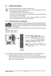
.../SS DS/SS (SS=Single-Sided, DS=Double-Sided, "- -"=No Memory) If two memory modules are to be used . (Go to GIGABYTE's website for optimum performance. Hardware Installation - 16 - If you are divided into two channels and each channel has two memory sockets as following..., the BIOS will double the original memory bandwidth. When enabling Dual Channel mode with two or four memory modules, it is recommended that the motherboard supports the memory. 1-4 Installing the Memory Read the following guidelines before you begin to CPU limitations, read the following : Channel 0: DDR2_1, ...
.../SS DS/SS (SS=Single-Sided, DS=Double-Sided, "- -"=No Memory) If two memory modules are to be used . (Go to GIGABYTE's website for optimum performance. Hardware Installation - 16 - If you are divided into two channels and each channel has two memory sockets as following..., the BIOS will double the original memory bandwidth. When enabling Dual Channel mode with two or four memory modules, it is recommended that the motherboard supports the memory. 1-4 Installing the Memory Read the following guidelines before you begin to CPU limitations, read the following : Channel 0: DDR2_1, ...

Manual
Page 17
..., make sure to turn off the computer and unplug the power cord from the power outlet to prevent damage to install DDR2 DIMMs on this motherboard.
..., make sure to turn off the computer and unplug the power cord from the power outlet to prevent damage to install DDR2 DIMMs on this motherboard.
Manual
Page 18
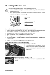
... on the card are completely inserted into the PCI Express slot. Secure the card's metal bracket to install an expansion card: • Make sure the motherboard supports the expansion card. Locate an expansion slot that came with your expansion card in the slot. 3. Install the driver provided with the expansion card...
... on the card are completely inserted into the PCI Express slot. Secure the card's metal bracket to install an expansion card: • Make sure the motherboard supports the expansion card. Locate an expansion slot that came with your expansion card in the slot. 3. Install the driver provided with the expansion card...
Manual
Page 19
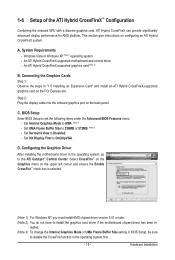
...; Control Center. An ATI Hybrid CrossFireX-supported graphics card (Note 2) B. C. Hardware Installation A. Configuring the Graphics Driver After installing the motherboard driver in the operating system first. - 19 - Set Surround View to OnChipVGA. Select CrossFire™ on the Graphics menu on the ...Requirements - D. Set Init Display First to Disabled. - BIOS Setup Enter BIOS Setup to install the graphics card driver if the motherboard chipset driver has been in "1-5 Installing an Expansion Card" and install an ATI Hybrid CrossFireX-supported graphics card on the PCI ...
...; Control Center. An ATI Hybrid CrossFireX-supported graphics card (Note 2) B. C. Hardware Installation A. Configuring the Graphics Driver After installing the motherboard driver in the operating system first. - 19 - Set Surround View to OnChipVGA. Select CrossFire™ on the Graphics menu on the ...Requirements - D. Set Init Display First to Disabled. - BIOS Setup Enter BIOS Setup to install the graphics card driver if the motherboard chipset driver has been in "1-5 Installing an Expansion Card" and install an ATI Hybrid CrossFireX-supported graphics card on the PCI ...
Manual
Page 21
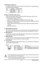
... ensure that supports digital optical audio. eSATA 3Gb/s Port The eSATA 3Gb/s port conforms to 1 Gbps data rate. Dual Display Configurations: This motherboard provides three ports for video output: DVI-D, HDMI and D-Sub. Do not rock it straight out from the connector. Before using this port...Hardware Acceleration is occurring • When removing the cable connected to an external audio system that your device and then remove it from the motherboard. • When removing the cable, pull it side to side to connect an external SATA device or a SATA port multiplier. A....
... ensure that supports digital optical audio. eSATA 3Gb/s Port The eSATA 3Gb/s port conforms to 1 Gbps data rate. Dual Display Configurations: This motherboard provides three ports for video output: DVI-D, HDMI and D-Sub. Do not rock it straight out from the connector. Before using this port...Hardware Acceleration is occurring • When removing the cable connected to an external audio system that your device and then remove it from the motherboard. • When removing the cable, pull it side to side to connect an external SATA device or a SATA port multiplier. A....

Manual
Page 23
...) SPDIF_IO 14) F_USB1/F_USB2/F_USB3 15) F_1394_1 16) LPT 17) COM 18) CI 19) CLR_CMOS 20) BATTERY Read the following guidelines before turning on the motherboard. - 23 - Hardware Installation Unplug the power cord from the power outlet to prevent damage to the devices. • After installing the device and before connecting...
...) SPDIF_IO 14) F_USB1/F_USB2/F_USB3 15) F_1394_1 16) LPT 17) COM 18) CI 19) CLR_CMOS 20) BATTERY Read the following guidelines before turning on the motherboard. - 23 - Hardware Installation Unplug the power cord from the power outlet to prevent damage to the devices. • After installing the device and before connecting...

Manual
Page 24
... a power supply providing a 2x4 12V and a 2x12 power connector, remove the protective covers from the 12V power connector and the main power connector on the motherboard. Before connecting the power connector, first make sure the power supply is turned off and all the components on the... motherboard. If the 12V power connector is not connected, the computer will not start. • To meet expansion requirements, it is used (500W or greater). Definition 1 3....
... a power supply providing a 2x4 12V and a 2x12 power connector, remove the protective covers from the 12V power connector and the main power connector on the motherboard. Before connecting the power connector, first make sure the power supply is turned off and all the components on the... motherboard. If the 12V power connector is not connected, the computer will not start. • To meet expansion requirements, it is used (500W or greater). Definition 1 3....

Manual
Page 25
... the CPU/North Bridge or the system may hang. • These fan headers are designed with colorcoded power connector wires. The motherboard supports CPU fan speed control, which requires the use of a CPU fan with color-coded power connector wires. Do not place ... connection and requires a +12V voltage. Pin No. Overheating may result in damage to connect it is the ground wire. 3/4) CPU_FAN/SYS_FAN (Fan Headers) The motherboard has a 4-pin CPU fan header (CPU_FAN)and a 4-pin system fan header(SYS_FAN). The fan header has a foolproof insertion design. Definition 1 GND 1 2...
... the CPU/North Bridge or the system may hang. • These fan headers are designed with colorcoded power connector wires. The motherboard supports CPU fan speed control, which requires the use of a CPU fan with color-coded power connector wires. Do not place ... connection and requires a +12V voltage. Pin No. Overheating may result in damage to connect it is the ground wire. 3/4) CPU_FAN/SYS_FAN (Fan Headers) The motherboard has a 4-pin CPU fan header (CPU_FAN)and a 4-pin system fan header(SYS_FAN). The fan header has a foolproof insertion design. Definition 1 GND 1 2...

Manual
Page 29
...module), refer to work or even damage it. Definition 10 9 1 MIC2_L Pin No. Pin No. Incorrect connection between the module connector and the motherboard header will be present on each wire instead of the front and back panel audio connections simultaneously. Definition 1 MIC 2 GND 2 1 3 MIC2_R ... optical drive to this header. Make sure the wire assignments of the module connector match the pin assignments of the motherboard header. For information about connecting the front panel audio module that came with your chassis front panel audio module to the...
...module), refer to work or even damage it. Definition 10 9 1 MIC2_L Pin No. Pin No. Incorrect connection between the module connector and the motherboard header will be present on each wire instead of the front and back panel audio connections simultaneously. Definition 1 MIC 2 GND 2 1 3 MIC2_R ... optical drive to this header. Make sure the wire assignments of the module connector match the pin assignments of the motherboard header. For information about connecting the front panel audio module that came with your chassis front panel audio module to the...
Manual
Page 32
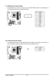
Definition 1 NDCD- 9 1 2 NSIN 10 2 3 NSOUT 4 NDTR- 5 GND 6 NDSR- 7 NRTS- 8 NCTS- 9 NRI- 10 No Pin 18) CI (Chassis Intrusion Header) This motherboard provides a chassis detection feature that detects if the chassis cover has been removed. This function requires a chassis with chassis intrusion detection design. Pin No. 17) ...
Definition 1 NDCD- 9 1 2 NSIN 10 2 3 NSOUT 4 NDTR- 5 GND 6 NDSR- 7 NRTS- 8 NCTS- 9 NRI- 10 No Pin 18) CI (Chassis Intrusion Header) This motherboard provides a chassis detection feature that detects if the chassis cover has been removed. This function requires a chassis with chassis intrusion detection design. Pin No. 17) ...


