Manual
Page 3
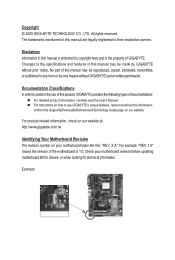
... types of the motherboard is the property of this manual may be reproduced, copied, translated, transmitted, or published in the use GIGABYTE's unique features, read the User's Manual. For instructions on how to the specifications and features in this : "REV...Motherboard\Technology Guide page on your motherboard revision before updating motherboard BIOS, drivers, or when looking for technical information. Check your motherboard looks like this manual may be made by GIGABYTE without GIGABYTE's prior written permission. For product-related information, check on...
... types of the motherboard is the property of this manual may be reproduced, copied, translated, transmitted, or published in the use GIGABYTE's unique features, read the User's Manual. For instructions on how to the specifications and features in this : "REV...Motherboard\Technology Guide page on your motherboard revision before updating motherboard BIOS, drivers, or when looking for technical information. Check your motherboard looks like this manual may be made by GIGABYTE without GIGABYTE's prior written permission. For product-related information, check on...

Manual
Page 4
Table of Contents Box Contents...6 Optional Items...6 GA-MA74GM-S2H/GA-MA74GM-S2 Motherboard Layout 7 Block Diagram...8 Chapter 1 Hardware Installation 9 1-1 Installation Precautions 9 1-2 Product Specifications 10 1-3 Installing the CPU and CPU...Installing an Expansion Card 18 1-6 Back Panel Connectors 19 1-7 Internal Connectors 21 Chapter 2 BIOS Setup 31 2-1 Startup Screen 32 2-2 The Main Menu 33 2-3 MB Intelligent Tweaker(M.I.T 35 2-4 Standard CMOS Features 40 2-5 Advanced BIOS Features 42 2-6 Integrated Peripherals 44 2-7 Power Management Setup 47 2-8 PnP/PCI Configurations ...
Table of Contents Box Contents...6 Optional Items...6 GA-MA74GM-S2H/GA-MA74GM-S2 Motherboard Layout 7 Block Diagram...8 Chapter 1 Hardware Installation 9 1-1 Installation Precautions 9 1-2 Product Specifications 10 1-3 Installing the CPU and CPU...Installing an Expansion Card 18 1-6 Back Panel Connectors 19 1-7 Internal Connectors 21 Chapter 2 BIOS Setup 31 2-1 Startup Screen 32 2-2 The Main Menu 33 2-3 MB Intelligent Tweaker(M.I.T 35 2-4 Standard CMOS Features 40 2-5 Advanced BIOS Features 42 2-6 Integrated Peripherals 44 2-7 Power Management Setup 47 2-8 PnP/PCI Configurations ...

Manual
Page 5
... 56 3-3 Technical Manuals 56 3-4 Contact...57 3-5 System...57 3-6 Download Center 58 Chapter 4 Unique Features 59 4-1 Xpress Recovery2 59 4-2 BIOS Update Utilities 62 4-2-1 Updating the BIOS with the Q-Flash Utility 62 4-2-2 Updating the BIOS with the @BIOS Utility 65 4-3 EasyTune 6...66 4-4 Q-Share...67 4-5 Time Repair...68 Chapter 5 Appendix...69 5-1 Configuring SATA Hard Drive(s 69 5-1-1 Configuring...
... 56 3-3 Technical Manuals 56 3-4 Contact...57 3-5 System...57 3-6 Download Center 58 Chapter 4 Unique Features 59 4-1 Xpress Recovery2 59 4-2 BIOS Update Utilities 62 4-2-1 Updating the BIOS with the Q-Flash Utility 62 4-2-2 Updating the BIOS with the @BIOS Utility 65 4-3 EasyTune 6...66 4-4 Q-Share...67 4-5 Time Repair...68 Chapter 5 Appendix...69 5-1 Configuring SATA Hard Drive(s 69 5-1-1 Configuring...

Manual
Page 8
... AMD SB710 ATA-133/100/66/33 IDE Channel 4 SATA 3Gb/s CODEC LPC Bus IT8718 Dual BIOS Floppy COM Port 2 PCI PS/2 KB or Mouse MIC Line Out Line In S/PDIF In S/PDIF Out PCI CLK (33 MHz) j (Note) Only for GA-MA74GM-S2H Simultaneous output for DVI-D and HDMI is not supported. - 8 -
... AMD SB710 ATA-133/100/66/33 IDE Channel 4 SATA 3Gb/s CODEC LPC Bus IT8718 Dual BIOS Floppy COM Port 2 PCI PS/2 KB or Mouse MIC Line Out Line In S/PDIF In S/PDIF Out PCI CLK (33 MHz) j (Note) Only for GA-MA74GM-S2H Simultaneous output for DVI-D and HDMI is not supported. - 8 -
Manual
Page 11
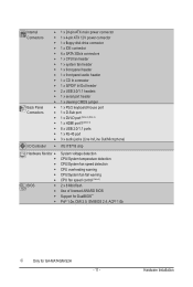
... chip Hardware Monitor w w w w w w BIOS w w w w System voltage detection CPU/System temperature detection CPU/System fan speed detection CPU overheating warning CPU/System fan fail warning CPU fan speed control (Note 5) 2 x 8 Mbit flash Use of licensed AWARD BIOS Support for DualBIOS™ PnP 1.0a, DMI 2.0, SM BIOS 2.4, ACPI 1.0b j Only for GA-MA74GM-S2H - 11 - Hardware Installation
... chip Hardware Monitor w w w w w w BIOS w w w w System voltage detection CPU/System temperature detection CPU/System fan speed detection CPU overheating warning CPU/System fan fail warning CPU fan speed control (Note 5) 2 x 8 Mbit flash Use of licensed AWARD BIOS Support for DualBIOS™ PnP 1.0a, DMI 2.0, SM BIOS 2.4, ACPI 1.0b j Only for GA-MA74GM-S2H - 11 - Hardware Installation
Manual
Page 12
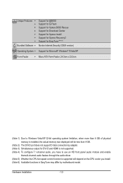
Hardware Installation - 12 - Unique Features w w w w w w w Bundled Software w Support for @BIOS Support for Q-Flash Support for Xpress BIOS Rescue Support for Download Center Support for Xpress Install Support for Xpress Recovery2 Support for EasyTune (Note 6) Norton Internet Security (OEM version) Operating System w Support ...
Hardware Installation - 12 - Unique Features w w w w w w w Bundled Software w Support for @BIOS Support for Q-Flash Support for Xpress BIOS Rescue Support for Download Center Support for Xpress Install Support for Xpress Recovery2 Support for EasyTune (Note 6) Norton Internet Security (OEM version) Operating System w Support ...
Manual
Page 16
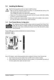
A memory module can be used . (Go to GIGABYTE's website for the latest memory support list.) • Always turn off the computer and unplug the power cord from the power outlet before installing the memory in only one DDR2 memory module is installed, the BIOS will double the original memory bandwidth. If you begin...
A memory module can be used . (Go to GIGABYTE's website for the latest memory support list.) • Always turn off the computer and unplug the power cord from the power outlet before installing the memory in only one DDR2 memory module is installed, the BIOS will double the original memory bandwidth. If you begin...

Manual
Page 18
... sure the card is fully inserted into the slot. 4. Carefully read the manual that supports your expansion card(s). 7. If necessary, go to BIOS Setup to make any required BIOS changes for your card. Remove the metal slot cover from the power outlet before you begin to the chassis back panel with the...
... sure the card is fully inserted into the slot. 4. Carefully read the manual that supports your expansion card(s). 7. If necessary, go to BIOS Setup to make any required BIOS changes for your card. Remove the metal slot cover from the power outlet before you begin to the chassis back panel with the...
Manual
Page 19
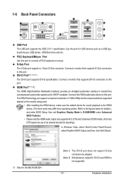
..., then set Graphics Display Mode to this port. Connect a monitor that supports DVI-D connection to D-SUB/HDMI under Advanced BIOS Features. • Please note the HDMI audio output only supports AC3, DTS and 2-channel-LPCM formats. (AC3 and DTS require the use of 1920x1080p... system. Hardware Installation Use this port. PS/2 Keyboard/Mouse Port Use this port to this port for DVI-D and HDMI is HDCP compliant. j Only for GA-MA74GM-S2H (Note 1) The DVI-D port does not support D-Sub connection by adapter. (Note 2) Simultaneous output for USB devices such as a USB keyboard/mouse, ...
..., then set Graphics Display Mode to this port. Connect a monitor that supports DVI-D connection to D-SUB/HDMI under Advanced BIOS Features. • Please note the HDMI audio output only supports AC3, DTS and 2-channel-LPCM formats. (AC3 and DTS require the use of 1920x1080p... system. Hardware Installation Use this port. PS/2 Keyboard/Mouse Port Use this port to this port for DVI-D and HDMI is HDCP compliant. j Only for GA-MA74GM-S2H (Note 1) The DVI-D port does not support D-Sub connection by adapter. (Note 2) Simultaneous output for USB devices such as a USB keyboard/mouse, ...
Manual
Page 20
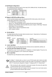
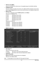
...(or better) below shows the supported dual display configurations. The following describes the states of UMA Frame Buffer Size (refer to Chapter 2, "BIOS Setup," "Advanced BIOS Features," for a headphone or 2-channel speaker. Use this audio jack for more information) • Playback software: CyberLink PowerDVD 8.0 or later...Phenom™ X3 processor or above • Memory: Two 1 GB DDR2 800 MHz memory modules with dual channel mode enabled • BIOS Setup: At least 256 MB of the LAN port LEDs. This jack can be connected to use an HD front panel audio module and...
...(or better) below shows the supported dual display configurations. The following describes the states of UMA Frame Buffer Size (refer to Chapter 2, "BIOS Setup," "Advanced BIOS Features," for a headphone or 2-channel speaker. Use this audio jack for more information) • Playback software: CyberLink PowerDVD 8.0 or later...Phenom™ X3 processor or above • Memory: Two 1 GB DDR2 800 MHz memory modules with dual channel mode enabled • BIOS Setup: At least 256 MB of the LAN port LEDs. This jack can be connected to use an HD front panel audio module and...

Manual
Page 25
... is operating. This function requires a chassis with a chassis intrusion switch/sensor. When connecting your system using the power switch (refer to Chapter 2, "BIOS Setup," "Power Management Setup," for information about beep codes. • HD (Hard Drive Activity LED, Blue) Connects to the power status indicator on... switch, power LED, hard drive activity LED, speaker and etc. Hardware Installation The LED is on when the hard drive is detected, the BIOS may configure the way to turn off (S5). • PW (Power Switch, Red): Connects to the power switch on the chassis front ...
... is operating. This function requires a chassis with a chassis intrusion switch/sensor. When connecting your system using the power switch (refer to Chapter 2, "BIOS Setup," "Power Management Setup," for information about beep codes. • HD (Hard Drive Activity LED, Blue) Connects to the power status indicator on... switch, power LED, hard drive activity LED, speaker and etc. Hardware Installation The LED is on when the hard drive is detected, the BIOS may configure the way to turn off (S5). • PW (Power Switch, Red): Connects to the power switch on the chassis front ...
Manual
Page 28
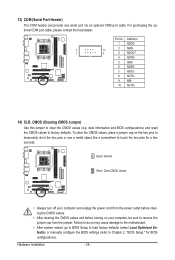
...the CMOS values and before turning on the two pins to temporarily short the two pins or use a metal object like a screwdriver to Chapter 2, "BIOS Setup," for a few seconds. To clear the CMOS values, place a jumper cap on your computer and unplug the power cord from the jumper. Failure... so may cause damage to the motherboard. • After system restart, go to BIOS Setup to load factory defaults (select Load Optimized Defaults) or manually configure the BIOS settings (refer to touch the two pins for BIOS configurations). 13) COM (Serial Port Header) The COM header can provide one serial...
...the CMOS values and before turning on the two pins to temporarily short the two pins or use a metal object like a screwdriver to Chapter 2, "BIOS Setup," for a few seconds. To clear the CMOS values, place a jumper cap on your computer and unplug the power cord from the jumper. Failure... so may cause damage to the motherboard. • After system restart, go to BIOS Setup to load factory defaults (select Load Optimized Defaults) or manually configure the BIOS settings (refer to touch the two pins for BIOS configurations). 13) COM (Serial Port Header) The COM header can provide one serial...

Manual
Page 29
... battery (the positive side should face up). • Used batteries must be lost. 15) BAT The battery provides power to keep the values (such as BIOS configurations, date, and time information) in the CMOS when the computer is replaced with an incorrect model. • Contact the place of purchase or local...
... battery (the positive side should face up). • Used batteries must be lost. 15) BAT The battery provides power to keep the values (such as BIOS configurations, date, and time information) in the CMOS when the computer is replaced with an incorrect model. • Contact the place of purchase or local...

Manual
Page 31
..., refer to prevent system instability or other unexpected results. To upgrade the BIOS, use either the GIGABYTE Q-Flash or @BIOS utility. • Q-Flash allows the user to activate certain system features. BIOS includes a BIOS Setup program that you not flash the BIOS. For instructions on the motherboard supplies the necessary power to the CMOS to boot...
..., refer to prevent system instability or other unexpected results. To upgrade the BIOS, use either the GIGABYTE Q-Flash or @BIOS utility. • Q-Flash allows the user to activate certain system features. BIOS includes a BIOS Setup program that you not flash the BIOS. For instructions on the motherboard supplies the necessary power to the CMOS to boot...

Manual
Page 32
AMD RS740 BIOS for GA-MA74GM-S2H FAa . . . . : BIOS Setup : XpressRecovery2 : Boot Menu : Qflash 08/27/2009-RS740-SB710-6A669G0AC-00 Function Keys Function Keys: : BIOS SETUP Press the key to enter BIOS Setup or to access the Q-Flash utility in BIOS Setup. : XPRESS RECOVERY2 If you to Xpress Recovery2 during the POST. In...to back up arrow key or the down arrow key to select the first boot device, then press to enter BIOS Setup first. You can be based on BIOS Setup settings. 2-1 Startup Screen The following screens may appear when the computer boots. The system will still be ...
AMD RS740 BIOS for GA-MA74GM-S2H FAa . . . . : BIOS Setup : XpressRecovery2 : Boot Menu : Qflash 08/27/2009-RS740-SB710-6A669G0AC-00 Function Keys Function Keys: : BIOS SETUP Press the key to enter BIOS Setup or to access the Q-Flash utility in BIOS Setup. : XPRESS RECOVERY2 If you to Xpress Recovery2 during the POST. In...to back up arrow key or the down arrow key to select the first boot device, then press to enter BIOS Setup first. You can be based on BIOS Setup settings. 2-1 Startup Screen The following screens may appear when the computer boots. The system will still be ...
Manual
Page 33
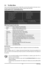
...the items and press to accept or enter a sub-menu. (Sample BIOS Version: GA-MA74GM-S2H FAa) CMOS Setup Utility-Copyright (C) 1984-2009 Award Software MB Intelligent Tweaker(M.I.T.) Standard CMOS Features Advanced BIOS Features Integrated Peripherals Power Management Setup PnP...; When the system is not stable as usual, select the Load Optimized Defaults item to set your system to BIOS Load CMOS from BIOS BIOS Setup Program Function Keys Move the selection bar to select an item Execute command or enter the submenu Main Menu:...
...the items and press to accept or enter a sub-menu. (Sample BIOS Version: GA-MA74GM-S2H FAa) CMOS Setup Utility-Copyright (C) 1984-2009 Award Software MB Intelligent Tweaker(M.I.T.) Standard CMOS Features Advanced BIOS Features Integrated Peripherals Power Management Setup PnP...; When the system is not stable as usual, select the Load Optimized Defaults item to set your system to BIOS Load CMOS from BIOS BIOS Setup Program Function Keys Move the selection bar to select an item Execute command or enter the submenu Main Menu:...

Manual
Page 34
... & Exit Setup Save all changes and the previous settings remain in effect. A supervisor password allows you to restrict access to load the BIOS settings from BIOS If your CPU, memory, etc. Standard CMOS Features Use this menu to configure the system time and date, hard drive types... MB Intelligent Tweaker(M.I.T.) Use this menu to configure the clock, frequency and voltages of your system becomes unstable and you have loaded the BIOS default settings, you can use the SPACE key) and then press to complete. F12: Load CMOS from a profile created before,...
... & Exit Setup Save all changes and the previous settings remain in effect. A supervisor password allows you to restrict access to load the BIOS settings from BIOS If your CPU, memory, etc. Standard CMOS Features Use this menu to configure the system time and date, hard drive types... MB Intelligent Tweaker(M.I.T.) Use this menu to configure the clock, frequency and voltages of your system becomes unstable and you have loaded the BIOS default settings, you can use the SPACE key) and then press to complete. F12: Load CMOS from a profile created before,...
Manual
Page 35
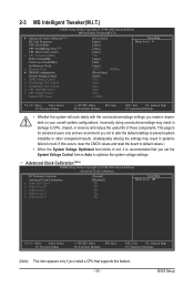
... blinks in damage to CPU, chipset, or memory and reduce the useful life of these components. This page is dependent on your overall system configurations. BIOS Setup If this feature. - 35 - Incorrectly doing overclock/overvoltage may result in system's failure to boot. 2-3 MB Intelligent Tweaker(M.I.T.) CMOS Setup Utility-Copyright (C) 1984-2009...
... blinks in damage to CPU, chipset, or memory and reduce the useful life of these components. This page is dependent on your overall system configurations. BIOS Setup If this feature. - 35 - Incorrectly doing overclock/overvoltage may result in system's failure to boot. 2-3 MB Intelligent Tweaker(M.I.T.) CMOS Setup Utility-Copyright (C) 1984-2009...
Manual
Page 36
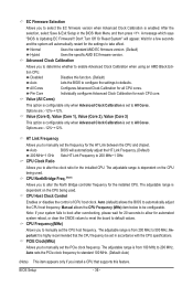
... Options are : -12%~+12%. The adjustable range is highly recommended that supports this function. (Default) Auto All Cores Lets the BIOS to configure the settings to automatically adjust the CPU host frequency. Note: If your system fails to boot after overclocking, please wait for.... Value (All Cores) This option is configurable only when Advanced Clock Calibration is from 200 MHz to All Cores. Auto (default) allows the BIOS to defaults. BIOS Setup - 36 - Value (Core 0), Value (Core 1), Value (Core 2), Value (Core 3) This option is configurable only when Advanced Clock...
... Options are : -12%~+12%. The adjustable range is highly recommended that supports this function. (Default) Auto All Cores Lets the BIOS to configure the settings to automatically adjust the CPU host frequency. Note: If your system fails to boot after overclocking, please wait for.... Value (All Cores) This option is configurable only when Advanced Clock Calibration is from 200 MHz to All Cores. Auto (default) allows the BIOS to defaults. BIOS Setup - 36 - Value (Core 0), Value (Core 1), Value (Core 2), Value (Core 3) This option is configurable only when Advanced Clock...
Manual
Page 37
Auto lets BIOS automatically set the VGA Core clock. X5.33 Sets Memory Clock to DDR 533. DDR 533 Sets Memory Clock to X5.33. Ganged Sets memory ....66 Sets Memory Clock to single dual-channel. When you install a CPU that supports this feature. - 37 - DDR 667 Sets Memory Clock to DDR 800. BIOS Setup DDR 800 Sets Memory Clock to DDR 667. Options are: Auto (default), Manual. (Note) This item appears only if you use an AM3/AM2...
Auto lets BIOS automatically set the VGA Core clock. X5.33 Sets Memory Clock to DDR 533. DDR 533 Sets Memory Clock to X5.33. Ganged Sets memory ....66 Sets Memory Clock to single dual-channel. When you install a CPU that supports this feature. - 37 - DDR 667 Sets Memory Clock to DDR 800. BIOS Setup DDR 800 Sets Memory Clock to DDR 667. Options are: Auto (default), Manual. (Note) This item appears only if you use an AM3/AM2...


