Manual
Page 3
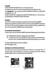
... Motherboard Revision The revision number on our website. The trademarks mentioned in any form or by GIGABYTE without GIGABYTE's prior written permission. is 1.0. For example, "REV: 1.0" means the revision of this ...: "REV: X.X." The logo is the property of documentations: „ For detailed product information, carefully read or download the information on/from the Support\Motherboard\Technology Guide page on your motherboard revision before updating motherboard BIOS...
... Motherboard Revision The revision number on our website. The trademarks mentioned in any form or by GIGABYTE without GIGABYTE's prior written permission. is 1.0. For example, "REV: 1.0" means the revision of this ...: "REV: X.X." The logo is the property of documentations: „ For detailed product information, carefully read or download the information on/from the Support\Motherboard\Technology Guide page on your motherboard revision before updating motherboard BIOS...

Manual
Page 4
Table of Contents Box Contents ...6 OptionalItems ...6 GA-M68SM-S2L Motherboard Layout 7 Block Diagram ...8 Chapter 1 Hardware Installation 9 1-1 Installation Precautions 9 1-2 Product Specifications 10 1-3 Installing the CPU and CPU Cooler 12... Memory 16 1-5 Installing an Expansion Card 17 1-6 Back Panel Connectors 18 1-7 Internal Connectors 20 Chapter 2 BIOS Setup 31 2-1 Startup Screen 32 2-2 The Main Menu 33 2-3 Standard CMOS Features 35 2-4 Advanced BIOS Features 37 2-5 IntegratedPeripherals 39 2-6 Power Management Setup 43 2-7 PnP/PCI Configurations 45 2-8 PC Health Status...
Table of Contents Box Contents ...6 OptionalItems ...6 GA-M68SM-S2L Motherboard Layout 7 Block Diagram ...8 Chapter 1 Hardware Installation 9 1-1 Installation Precautions 9 1-2 Product Specifications 10 1-3 Installing the CPU and CPU Cooler 12... Memory 16 1-5 Installing an Expansion Card 17 1-6 Back Panel Connectors 18 1-7 Internal Connectors 20 Chapter 2 BIOS Setup 31 2-1 Startup Screen 32 2-2 The Main Menu 33 2-3 Standard CMOS Features 35 2-4 Advanced BIOS Features 37 2-5 IntegratedPeripherals 39 2-6 Power Management Setup 43 2-7 PnP/PCI Configurations 45 2-8 PC Health Status...

Manual
Page 5
... 52 3-3 Driver CD Information 52 3-4 Hardware Information 53 3-5 Contact Us ...53 Chapter 4 Unique Features 55 4-1 Xpress Recovery2 55 4-2 BIOS Update Utilities 60 4-2-1 Updating the BIOS with the Q-Flash Utility 60 4-2-2 Updating the BIOS with the @BIOS Utility 63 4-3 EasyTune 5 ...65 4-4 Windows Vista ReadyBoost 66 Chapter 5 Appendix ...67 5-1 Configuring SATA Hard Drive(s 67 5-1-1 Configuring the...
... 52 3-3 Driver CD Information 52 3-4 Hardware Information 53 3-5 Contact Us ...53 Chapter 4 Unique Features 55 4-1 Xpress Recovery2 55 4-2 BIOS Update Utilities 60 4-2-1 Updating the BIOS with the Q-Flash Utility 60 4-2-2 Updating the BIOS with the @BIOS Utility 63 4-3 EasyTune 5 ...65 4-4 Windows Vista ReadyBoost 66 Chapter 5 Appendix ...67 5-1 Configuring SATA Hard Drive(s 67 5-1-1 Configuring the...

Manual
Page 8
Block Diagram PCIe CLK (100 MHz) AMD Socket AM2 CPU CPU CLK+/-(200 MHz) DDR2 800/667/533 MHz DIMM Hyper Transport Dual Channel Memory PCI Express x16 DVI-D PCI Express Bus x1 PCIe CLK (100 MHz) 1 PCI Express x1 PCI Bus D-Sub RTL 8211BL LAN RJ45 nVIDIA® GeForce 7025/ nForce 630a 4 SATA 3Gb/s ATA-133/100/66/33 IDE Channel BIOS LPC BUS IT8716 Floppy LPT Port COM Port CODEC PS/2 KB/Mouse 10 USB Ports 2 PCI PCI CLK (33 MHz) MIC (Center/Subwoofer Speaker Out) Line-Out (Front Speaker Out) Line-In (Rear Speaker Out) SPDIF Out - 8 -
Block Diagram PCIe CLK (100 MHz) AMD Socket AM2 CPU CPU CLK+/-(200 MHz) DDR2 800/667/533 MHz DIMM Hyper Transport Dual Channel Memory PCI Express x16 DVI-D PCI Express Bus x1 PCIe CLK (100 MHz) 1 PCI Express x1 PCI Bus D-Sub RTL 8211BL LAN RJ45 nVIDIA® GeForce 7025/ nForce 630a 4 SATA 3Gb/s ATA-133/100/66/33 IDE Channel BIOS LPC BUS IT8716 Floppy LPT Port COM Port CODEC PS/2 KB/Mouse 10 USB Ports 2 PCI PCI CLK (33 MHz) MIC (Center/Subwoofer Speaker Out) Line-Out (Front Speaker Out) Line-In (Rear Speaker Out) SPDIF Out - 8 -

Manual
Page 11
...fail warning Š CPU fan speed control (Note 2) Š 1 x 4 Mbit flash Š Use of licensed AWARD BIOS Š PnP 1.0a, DMI 2.0, SM BIOS 2.4, ACPI 1.0b Š Support for @BIOS Š Support for Download Center Š Support for Q-Flash Š Support for EasyTune (Note 3) Š Support for ...Xpress Install Š Support for Xpress Recovery2 Š Support for Virtual Dual BIOS Š Norton Internet Security (OEM version) Š Support for Microsoft® Windows® Vista/XP/2000 Š Micro ATX form factor; 24....
...fail warning Š CPU fan speed control (Note 2) Š 1 x 4 Mbit flash Š Use of licensed AWARD BIOS Š PnP 1.0a, DMI 2.0, SM BIOS 2.4, ACPI 1.0b Š Support for @BIOS Š Support for Download Center Š Support for Q-Flash Š Support for EasyTune (Note 3) Š Support for ...Xpress Install Š Support for Xpress Recovery2 Š Support for Virtual Dual BIOS Š Norton Internet Security (OEM version) Š Support for Microsoft® Windows® Vista/XP/2000 Š Micro ATX form factor; 24....

Manual
Page 15
... that memory of the memory. Hardware Installation When enabling Dual Channel mode with two memory modules, it is installed, the BIOS will double the original memory bandwidth. If you begin to GIGABYTE's website for the latest memory support list.) • Always turn off the computer and unplug the power cord from the...
... that memory of the memory. Hardware Installation When enabling Dual Channel mode with two memory modules, it is installed, the BIOS will double the original memory bandwidth. If you begin to GIGABYTE's website for the latest memory support list.) • Always turn off the computer and unplug the power cord from the...

Manual
Page 17
... card until it is fully seated in the expansion slot. 1. After installing all expansion cards, replace the chassis cover(s). 6. Hardware Installation If necessary, go to BIOS Setup to prevent hardware damage. Make sure the card is fully inserted into the slot. 4. Carefully read the manual that supports your computer. Install the... card straight out from the chassis back panel. 2. 1-5 Installing an Expansion Card Read the following guidelines before installing an expansion card to make any required BIOS changes for your expansion card(s). 7.
... card until it is fully seated in the expansion slot. 1. After installing all expansion cards, replace the chassis cover(s). 6. Hardware Installation If necessary, go to BIOS Setup to prevent hardware damage. Make sure the card is fully inserted into the slot. 4. Carefully read the manual that supports your computer. Install the... card straight out from the chassis back panel. 2. 1-5 Installing an Expansion Card Read the following guidelines before installing an expansion card to make any required BIOS changes for your expansion card(s). 7.

Manual
Page 24
...environmental regulations. System Status LED S0 On S1 Blinking S3/S4/S5 Off 9) BATTERY The battery provides power to keep the values (such as BIOS configurations, date, and time information) in the power cord and restart your computer. • Always turn off your computer and unplug the power... you are not able to replace the battery by removing the battery: 1. Plug in the CMOS when the computer is turned off (S5). GA-M68SM-S2L Motherboard - 24 - You may be lost. Danger of explosion if the battery is in accordance with an incorrect model. • Contact the...
...environmental regulations. System Status LED S0 On S1 Blinking S3/S4/S5 Off 9) BATTERY The battery provides power to keep the values (such as BIOS configurations, date, and time information) in the power cord and restart your computer. • Always turn off your computer and unplug the power... you are not able to replace the battery by removing the battery: 1. Plug in the CMOS when the computer is turned off (S5). GA-M68SM-S2L Motherboard - 24 - You may be lost. Danger of explosion if the battery is in accordance with an incorrect model. • Contact the...

Manual
Page 25
... Status LED Connects to the power status indicator on the chassis front panel. The LED keeps blinking when S1 Blinking the system is detected, the BIOS may issue beeps in S3/S4/S5 Off S3/S4 sleep state or powered off (S5). • PW (Power Switch): Connects to the ... connection The front panel design may configure the way to the pin assignments below. When connecting your system using the power switch (refer to Chapter 2, "BIOS Setup," "Power Management Setup," for information about beep codes. • HD (IDE Hard Drive Activity LED) Connects to the reset switch on when the...
... Status LED Connects to the power status indicator on the chassis front panel. The LED keeps blinking when S1 Blinking the system is detected, the BIOS may issue beeps in S3/S4/S5 Off S3/S4 sleep state or powered off (S5). • PW (Power Switch): Connects to the ... connection The front panel design may configure the way to the pin assignments below. When connecting your system using the power switch (refer to Chapter 2, "BIOS Setup," "Power Management Setup," for information about beep codes. • HD (IDE Hard Drive Activity LED) Connects to the reset switch on when the...

Manual
Page 29
...the motherboard. • After system restart, go to BIOS Setup to load factory defaults (select Load Optimized Defaults) or manually configure the BIOS settings (refer to clear the CMOS values (e.g. 17) CLR_CMOS (Clearing CMOS Jumper) Use this jumper to Chapter 2, "BIOS Setup," for a few seconds. To clear the CMOS... values, place a jumper cap on your computer, be sure to touch the two pins for BIOS configurations). - 29 - Hardware Installation Open: Normal Short: Clear CMOS Values • Always turn off your computer and unplug the power cord...
...the motherboard. • After system restart, go to BIOS Setup to load factory defaults (select Load Optimized Defaults) or manually configure the BIOS settings (refer to clear the CMOS values (e.g. 17) CLR_CMOS (Clearing CMOS Jumper) Use this jumper to Chapter 2, "BIOS Setup," for a few seconds. To clear the CMOS... values, place a jumper cap on your computer, be sure to touch the two pins for BIOS configurations). - 29 - Hardware Installation Open: Normal Short: Clear CMOS Values • Always turn off your computer and unplug the power cord...

Manual
Page 31
When the power is a Windows-based utility that you do it is turned on the motherboard. To upgrade the BIOS, use either the GIGABYTE Q-Flash or @BIOS utility. • Q-Flash allows the user to boot. Inadequately altering the settings may result in Chapter 1 for the beep codes... description. • It is potentially risky, if you not flash the BIOS. BIOS Setup For instructions on the motherboard supplies ...
When the power is a Windows-based utility that you do it is turned on the motherboard. To upgrade the BIOS, use either the GIGABYTE Q-Flash or @BIOS utility. • Q-Flash allows the user to boot. Inadequately altering the settings may result in Chapter 1 for the beep codes... description. • It is potentially risky, if you not flash the BIOS. BIOS Setup For instructions on the motherboard supplies ...

Manual
Page 32
... configured in Boot Menu. Note: The setting in BIOS Setup. : Xpress Recovery2 If you to accept. GA-M68SM-S2L Motherboard - 32 - M68SM-S2L D1 . . . . : BIOS Setup/Q-Flash : XpressRecovery2 : Boot Menu : Qflash 09/11/2007-NF-MCP68-6A61MG02C-00 Function Keys Function Keys: : BIOS Setup/Q-Flash Press the key to enter BIOS Setup or to access the Q-Flash utility in...
... configured in Boot Menu. Note: The setting in BIOS Setup. : Xpress Recovery2 If you to accept. GA-M68SM-S2L Motherboard - 32 - M68SM-S2L D1 . . . . : BIOS Setup/Q-Flash : XpressRecovery2 : Boot Menu : Qflash 09/11/2007-NF-MCP68-6A61MG02C-00 Function Keys Function Keys: : BIOS Setup/Q-Flash Press the key to enter BIOS Setup or to access the Q-Flash utility in...

Manual
Page 33
...block on the right (submenus only) Restore the previous BIOS settings for the current submenus Load the Fail-Safe BIOS default settings for the current submenus Load the Optimized BIOS default settings for the menu. BIOS Setup BIOS Setup Program Function Keys Move the selection bar to ...of function keys available for the current submenus Access the Q-Flash utility Display system information Save all the changes and exit the BIOS Setup program Main Menu Help The onscreen description of a highlighted setup option is in a submenu, press to accept or enter a sub...
...block on the right (submenus only) Restore the previous BIOS settings for the current submenus Load the Fail-Safe BIOS default settings for the current submenus Load the Optimized BIOS default settings for the menu. BIOS Setup BIOS Setup Program Function Keys Move the selection bar to ...of function keys available for the current submenus Access the Q-Flash utility Display system information Save all the changes and exit the BIOS Setup program Main Menu Help The onscreen description of a highlighted setup option is in a submenu, press to accept or enter a sub...

Manual
Page 34
... disable password. Pressing to the confirmation message will exit BIOS Setup. (Pressing can also carry out this task.) GA-M68SM-S2L Motherboard - 34 - It allows you to restrict access to the system and BIOS Setup. A supervisor password allows you to view the BIOS settings but not to make changes in effect. „...and date, hard drive types, floppy disk drive types, and the type of errors that stop the system boot, etc. „ Advanced BIOS Features Use this menu to configure the device boot order, advanced features available on the CPU, and the primary display adapter. „ ...
... disable password. Pressing to the confirmation message will exit BIOS Setup. (Pressing can also carry out this task.) GA-M68SM-S2L Motherboard - 34 - It allows you to restrict access to the system and BIOS Setup. A supervisor password allows you to view the BIOS settings but not to make changes in effect. „...and date, hard drive types, floppy disk drive types, and the type of errors that stop the system boot, etc. „ Advanced BIOS Features Use this menu to configure the device boot order, advanced features available on the CPU, and the primary display adapter. „ ...

Manual
Page 35
...(read-only), month, date and year. Extended IDE Drive Configure your IDE/SATA devices by using one of the two methods below : • Auto Lets BIOS automatically detect IDE/SATA devices during the POST. (Default) • None If no IDE/SATA devices are used , set the date... Auto-Detection Press to CHS. IDE Channel 0 Master/Slave Configure your IDE/SATA devices by using one of the three methods below : • Auto Lets BIOS automatically detect IDE/SATA devices during the POST. (Default) • None If no IDE/SATA devices are used , set this item to None so the...
...(read-only), month, date and year. Extended IDE Drive Configure your IDE/SATA devices by using one of the two methods below : • Auto Lets BIOS automatically detect IDE/SATA devices during the POST. (Default) • None If no IDE/SATA devices are used , set the date... Auto-Detection Press to CHS. IDE Channel 0 Master/Slave Configure your IDE/SATA devices by using one of the three methods below : • Auto Lets BIOS automatically detect IDE/SATA devices during the POST. (Default) • None If no IDE/SATA devices are used , set this item to None so the...
Manual
Page 36
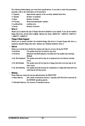
...Landing zone. Sector Number of cylinders. Whenever the BIOS detects a non-fatal error the system boot will stop. (Default) All, But Keyboard The system boot will stop for all other errors. Base Memory Also called conventional memory. GA-M68SM-S2L Motherboard - 36 - Drive A Allows you to... the information on Allows you do not install a floppy disk drive, set this item to None. Options are determined by the BIOS POST. Halt on the hard drive. Cylinder ...
...Landing zone. Sector Number of cylinders. Whenever the BIOS detects a non-fatal error the system boot will stop. (Default) All, But Keyboard The system boot will stop for all other errors. Base Memory Also called conventional memory. GA-M68SM-S2L Motherboard - 36 - Drive A Allows you to... the information on Allows you do not install a floppy disk drive, set this item to None. Options are determined by the BIOS POST. Halt on the hard drive. Cylinder ...

Manual
Page 37
... of loading the operating system from the available devices. Press to accept. 2-4 Advanced BIOS Features CMOS Setup Utility-Copyright (C) 1984-2007 Award Software Advanced BIOS Features Virtualization AMD K8 Cool&Quiet control ` Hard Disk Boot Priority First Boot Device ...and its power consumption. (Default) Disabled Disable this item, set the password(s) under the Set Supervisor/User Password item in independent partitions. BIOS Setup Capability Away Mode Init Display First iGPU Frame Buffer Control x Frame Buffer Size [Disabled] [Auto] [Press Enter] [Floppy] [Hard...
... of loading the operating system from the available devices. Press to accept. 2-4 Advanced BIOS Features CMOS Setup Utility-Copyright (C) 1984-2007 Award Software Advanced BIOS Features Virtualization AMD K8 Cool&Quiet control ` Hard Disk Boot Priority First Boot Device ...and its power consumption. (Default) Disabled Disable this item, set the password(s) under the Set Supervisor/User Password item in independent partitions. BIOS Setup Capability Away Mode Init Display First iGPU Frame Buffer Control x Frame Buffer Size [Disabled] [Auto] [Press Enter] [Floppy] [Hard...

Manual
Page 38
... Center operating system. iGPU Frame Buffer Control Auto Manual BIOS will use only this memory for display. Frame buffer size is the total amount of the monitor display from the installed PCI graphics card, PCI Express graphics card, or the onboard VGA. GA-M68SM-S2L Motherboard - 38 - PCI Slot Sets the PCI graphics card...
... Center operating system. iGPU Frame Buffer Control Auto Manual BIOS will use only this memory for display. Frame buffer size is the total amount of the monitor display from the installed PCI graphics card, PCI Express graphics card, or the onboard VGA. GA-M68SM-S2L Motherboard - 38 - PCI Slot Sets the PCI graphics card...

Manual
Page 39
BIOS Setup 2-5 Integrated Peripherals CMOS Setup Utility-Copyright (C) 1984-2007 Award Software Integrated Peripherals ` Serial-ATA RAID Config On-Chip IDE Channel0 IDE DMA transfer access ...
BIOS Setup 2-5 Integrated Peripherals CMOS Setup Utility-Copyright (C) 1984-2007 Award Software Integrated Peripherals ` Serial-ATA RAID Config On-Chip IDE Channel0 IDE DMA transfer access ...

Manual
Page 41
... Defaults ESC: Exit F1: General Help F7: Optimized Defaults This motherboard incorporates cable diagnostic feature designed to the following message will only operate at Port..... BIOS Setup it will operate at a normal speed of 10/100/1000 Mbps in Windows mode or when the LAN Boot ROM is detected on Pair 1-2.
... Defaults ESC: Exit F1: General Help F7: Optimized Defaults This motherboard incorporates cable diagnostic feature designed to the following message will only operate at Port..... BIOS Setup it will operate at a normal speed of 10/100/1000 Mbps in Windows mode or when the LAN Boot ROM is detected on Pair 1-2.


