
Manual
Page 3
...product. Example: The trademarks mentioned in this : "REV: X.X." For product-related information, check on our website at: http://www.gigabyte.com.tw Identifying Your Motherboard Revision The revision number on our website. Check your motherboard looks like this manual may be made by... set-up of GIGABYTE. For example, "REV: 1.0" means the revision of the motherboard is the property of the product, read or download the information on/from the Support&Downloads\Motherboard\Technology Guide page on your motherboard revision before updating motherboard BIOS, drivers, or when...
...product. Example: The trademarks mentioned in this : "REV: X.X." For product-related information, check on our website at: http://www.gigabyte.com.tw Identifying Your Motherboard Revision The revision number on our website. Check your motherboard looks like this manual may be made by... set-up of GIGABYTE. For example, "REV: 1.0" means the revision of the motherboard is the property of the product, read or download the information on/from the Support&Downloads\Motherboard\Technology Guide page on your motherboard revision before updating motherboard BIOS, drivers, or when...

Manual
Page 4
Table of Contents Box Contents...6 Optional Items...6 GA-H55M-UD2H/GA-H55M-US2H Motherboard Layout 7 Block Diagram...8 Chapter 1 Hardware Installation 9 1-1 Installation Precautions 9 1-2 Product Specifications 10 1-3 Installing the CPU and CPU ...1-5 Installing an Expansion Card 18 1-6 Back Panel Connectors 19 1-7 Internal Connectors 22 Chapter 2 BIOS Setup 33 2-1 Startup Screen 34 2-2 The Main Menu 35 2-3 MB Intelligent Tweaker(M.I.T 37 2-4 Standard CMOS Features 46 2-5 Advanced BIOS Features 48 2-6 Integrated Peripherals 50 2-7 Power Management Setup 53 2-8 PC Health Status 55 ...
Table of Contents Box Contents...6 Optional Items...6 GA-H55M-UD2H/GA-H55M-US2H Motherboard Layout 7 Block Diagram...8 Chapter 1 Hardware Installation 9 1-1 Installation Precautions 9 1-2 Product Specifications 10 1-3 Installing the CPU and CPU ...1-5 Installing an Expansion Card 18 1-6 Back Panel Connectors 19 1-7 Internal Connectors 22 Chapter 2 BIOS Setup 33 2-1 Startup Screen 34 2-2 The Main Menu 35 2-3 MB Intelligent Tweaker(M.I.T 37 2-4 Standard CMOS Features 46 2-5 Advanced BIOS Features 48 2-6 Integrated Peripherals 50 2-7 Power Management Setup 53 2-8 PC Health Status 55 ...

Manual
Page 5
... 62 3-4 Contact...63 3-5 System...63 3-6 Download Center 64 3-7 New Utilities...64 Chapter 4 Unique Features 65 4-1 Xpress Recovery2 65 4-2 BIOS Update Utilities 68 4-2-1 Updating the BIOS with the Q-Flash Utility 68 4-2-2 Updating the BIOS with the @BIOS Utility 71 4-3 EasyTune 6...72 4-4 Dynamic Energy Saver™ 2 73 4-5 Q-Share...75 4-6 Smart 6™...76 4-7 Auto Green...79 Chapter...
... 62 3-4 Contact...63 3-5 System...63 3-6 Download Center 64 3-7 New Utilities...64 Chapter 4 Unique Features 65 4-1 Xpress Recovery2 65 4-2 BIOS Update Utilities 68 4-2-1 Updating the BIOS with the Q-Flash Utility 68 4-2-2 Updating the BIOS with the @BIOS Utility 71 4-3 EasyTune 6...72 4-4 Dynamic Energy Saver™ 2 73 4-5 Q-Share...75 4-6 Smart 6™...76 4-7 Auto Green...79 Chapter...

Manual
Page 8
DisplayPortj, HDMI, and DVI-D) for GA-H55M-UD2H (Note) You can use only one of the onboard digital graphics ports (e.g. Block Diagram 1 PCI Express x16 LGA1156 CPU CPU ... PCI Bus TSB43AB23j 2 IEEE 1394aj FDI Interface DMI Interface Intel® H55 CODEC D-Sub DVI-D, HDMI, or DisplayPortj (Note) Dual BIOS 6 SATA 3Gb/s 12 USB Ports LPC Bus IT8720 Floppy COM Port PS/2 KB/Mouse Surround Speaker Out Center/Subwoofer Speaker Out Side ...Out Line In S/PDIF In S/PDIF Out 2 PCI PCI CLK (33 MHz) j Only for output when in the BIOS Setup program or when during the POST screens. - 8 -
DisplayPortj, HDMI, and DVI-D) for GA-H55M-UD2H (Note) You can use only one of the onboard digital graphics ports (e.g. Block Diagram 1 PCI Express x16 LGA1156 CPU CPU ... PCI Bus TSB43AB23j 2 IEEE 1394aj FDI Interface DMI Interface Intel® H55 CODEC D-Sub DVI-D, HDMI, or DisplayPortj (Note) Dual BIOS 6 SATA 3Gb/s 12 USB Ports LPC Bus IT8720 Floppy COM Port PS/2 KB/Mouse Surround Speaker Out Center/Subwoofer Speaker Out Side ...Out Line In S/PDIF In S/PDIF Out 2 PCI PCI CLK (33 MHz) j Only for output when in the BIOS Setup program or when during the POST screens. - 8 -

Manual
Page 12
...speed control (Note 7) 2 x 64 Mbit flash Use of licensed AWARD BIOS Support for DualBIOS™ PnP 1.0a, DMI 2.0, SM BIOS 2.4, ACPI 1.0b Support for @BIOS Support for Q-Flash Support for Xpress BIOS Rescue Support for Download Center Support for Xpress Install Support for Xpress Recovery2...cooler you install. (Note 8) Available functions in the BIOS Setup program or when during the POST screens. (Note 5) For optimum performance, if only one of the onboard digital graphics ports (e.g. DisplayPortj, HDMI, and DVI-D) for GA-H55M-UD2H Hardware Installation - 12 - j Only for output when...
...speed control (Note 7) 2 x 64 Mbit flash Use of licensed AWARD BIOS Support for DualBIOS™ PnP 1.0a, DMI 2.0, SM BIOS 2.4, ACPI 1.0b Support for @BIOS Support for Q-Flash Support for Xpress BIOS Rescue Support for Download Center Support for Xpress Install Support for Xpress Recovery2...cooler you install. (Note 8) Available functions in the BIOS Setup program or when during the POST screens. (Note 5) For optimum performance, if only one of the onboard digital graphics ports (e.g. DisplayPortj, HDMI, and DVI-D) for GA-H55M-UD2H Hardware Installation - 12 - j Only for output when...

Manual
Page 16
...Configuration This motherboard provides four DDR3 memory sockets and supports Dual Channel Technology. If only one DDR3 memory module is installed, be used. (Go to GIGABYTE's website for optimum performance. DS/SS Four Modules DS/SS DS/SS DS/SS DS/SS (SS=Single-Sided, DS=Double-Sided, "- -"=No...DS/SS - - When enabling Dual Channel mode with two or four memory modules, it in only one DDR3 memory module is installed, the BIOS will double the original memory bandwidth. Dual Channel mode cannot be sure to install them in Dual Channel mode. 1. When enabling Dual Channel mode ...
...Configuration This motherboard provides four DDR3 memory sockets and supports Dual Channel Technology. If only one DDR3 memory module is installed, be used. (Go to GIGABYTE's website for optimum performance. DS/SS Four Modules DS/SS DS/SS DS/SS DS/SS (SS=Single-Sided, DS=Double-Sided, "- -"=No...DS/SS - - When enabling Dual Channel mode with two or four memory modules, it in only one DDR3 memory module is installed, the BIOS will double the original memory bandwidth. Dual Channel mode cannot be sure to install them in Dual Channel mode. 1. When enabling Dual Channel mode ...

Manual
Page 18
... slot. Make sure the metal contacts on your expansion card(s). 7. Secure the card's metal bracket to make any required BIOS changes for your computer. Hardware Installation - 18 - If necessary, go to BIOS Setup to the chassis back panel with the expansion card in the slot. 3. Make sure the card is securely seated...
... slot. Make sure the metal contacts on your expansion card(s). 7. Secure the card's metal bracket to make any required BIOS changes for your computer. Hardware Installation - 18 - If necessary, go to BIOS Setup to the chassis back panel with the expansion card in the slot. 3. Make sure the card is securely seated...

Manual
Page 20
For example, in the BIOS Setup program or when during the POST screens. DisplayPortj, HDMI, and DVI-D) for the onboard .... DiplayPortj(Note 1)(Note 3) DisplayPort is one of the onboard digital graphics ports (e.g. After installing the DisplayPort device, make sure the default device for GA-H55M-UD2H Hardware Installation - 20 - Display Matrix Combination Supported or Not DVI-D + D-Sub Yes DVI-D + HDMI No DVI-D + DPj No HDMI ...set the DisplayPort device as the default playback device. There is no such limitation in the BIOS Setup program or when during the POST stage.
For example, in the BIOS Setup program or when during the POST screens. DisplayPortj, HDMI, and DVI-D) for the onboard .... DiplayPortj(Note 1)(Note 3) DisplayPort is one of the onboard digital graphics ports (e.g. After installing the DisplayPort device, make sure the default device for GA-H55M-UD2H Hardware Installation - 20 - Display Matrix Combination Supported or Not DVI-D + D-Sub Yes DVI-D + HDMI No DVI-D + DPj No HDMI ...set the DisplayPort device as the default playback device. There is no such limitation in the BIOS Setup program or when during the POST stage.

Manual
Page 26
... before replacing the battery. • Replace the battery with an equivalent one minute. (Or use a metal object like a screwdriver to keep the values (such as BIOS configurations, date, and time information) in accordance with an incorrect model. • Contact the place of purchase or local dealer if you are not able...
... before replacing the battery. • Replace the battery with an equivalent one minute. (Or use a metal object like a screwdriver to keep the values (such as BIOS configurations, date, and time information) in accordance with an incorrect model. • Contact the place of purchase or local dealer if you are not able...
Manual
Page 27
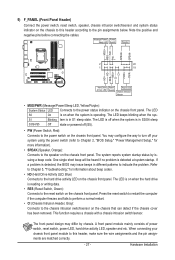
If a problem is detected, the BIOS may issue beeps in S1 sleep state. Press the reset switch to restart the computer if the computer freezes and fails to perform a normal restart. &#...; PW (Power Switch, Red): Connects to the power switch on the chassis front panel. When connecting your system using the power switch (refer to Chapter 2, "BIOS Setup," "Power Management Setup," for information about beep codes. • HD (Hard Drive Activity LED, Blue) Connects to the hard drive activity LED on the...
If a problem is detected, the BIOS may issue beeps in S1 sleep state. Press the reset switch to restart the computer if the computer freezes and fails to perform a normal restart. &#...; PW (Power Switch, Red): Connects to the power switch on the chassis front panel. When connecting your system using the power switch (refer to Chapter 2, "BIOS Setup," "Power Management Setup," for information about beep codes. • HD (Hard Drive Activity LED, Blue) Connects to the hard drive activity LED on the...
Manual
Page 31
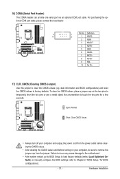
...Failure to do so may cause damage to the motherboard. • After system restart, go to BIOS Setup to load factory defaults (select Load Optimized Defaults) or manually configure the BIOS settings (refer to factory defaults. 16) COMA (Serial Port Header) The COMA header can provide one...- 5 GND 6 NDSR- 7 NRTS- 8 NCTS- 9 NRI- 10 No Pin 17) CLR_CMOS (Clearing CMOS Jumper) Use this jumper to touch the two pins for BIOS configurations). - 31 - Open: Normal Short: Clear CMOS Values • Always turn off your computer and unplug the power cord from the power outlet before clearing...
...Failure to do so may cause damage to the motherboard. • After system restart, go to BIOS Setup to load factory defaults (select Load Optimized Defaults) or manually configure the BIOS settings (refer to factory defaults. 16) COMA (Serial Port Header) The COMA header can provide one...- 5 GND 6 NDSR- 7 NRTS- 8 NCTS- 9 NRI- 10 No Pin 17) CLR_CMOS (Clearing CMOS Jumper) Use this jumper to touch the two pins for BIOS configurations). - 31 - Open: Normal Short: Clear CMOS Values • Always turn off your computer and unplug the power cord from the power outlet before clearing...

Manual
Page 33
...utility that allows the user to modify basic system configuration settings or to boot. BIOS Setup When the power is turned off, the battery on . To upgrade the BIOS, use either the GIGABYTE Q-Flash or @BIOS utility. • Q-Flash allows the user to quickly and easily upgrade or ...back up BIOS without entering the operating system. • @BIOS is recommended that you not flash the BIOS. Inadequately altering the settings may result...
...utility that allows the user to modify basic system configuration settings or to boot. BIOS Setup When the power is turned off, the battery on . To upgrade the BIOS, use either the GIGABYTE Q-Flash or @BIOS utility. • Q-Flash allows the user to quickly and easily upgrade or ...back up BIOS without entering the operating system. • @BIOS is recommended that you not flash the BIOS. Inadequately altering the settings may result...
Manual
Page 34
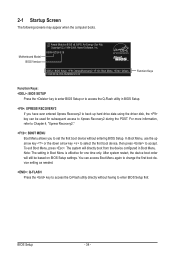
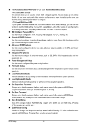
.... : Q-FLASH Press the key to accept. H55M-UD2H E18 . . . . : BIOS Setup : XpressRecovery2 : Boot Menu : Qflash 10/26/2009-H55-7A89RG0VC-00 Function Keys Function Keys: : BIOS SETUP Press the key to enter BIOS Setup or to access the Q-Flash utility in BIOS Setup. : XPRESS RECOVERY2 If you to set ...device boot order will directly boot from the device configured in Boot Menu is effective for subsequent access to enter BIOS Setup first. Motherboard Model BIOS Version Award Modular BIOS v6.00PG, An Energy Star Ally Copyright (C) 1984-2009, Award Software, Inc. The system will still be...
.... : Q-FLASH Press the key to accept. H55M-UD2H E18 . . . . : BIOS Setup : XpressRecovery2 : Boot Menu : Qflash 10/26/2009-H55-7A89RG0VC-00 Function Keys Function Keys: : BIOS SETUP Press the key to enter BIOS Setup or to access the Q-Flash utility in BIOS Setup. : XPRESS RECOVERY2 If you to set ...device boot order will directly boot from the device configured in Boot Menu is effective for subsequent access to enter BIOS Setup first. Motherboard Model BIOS Version Award Modular BIOS v6.00PG, An Energy Star Ally Copyright (C) 1984-2009, Award Software, Inc. The system will still be...
Manual
Page 35
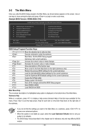
... your system to its defaults. • The BIOS Setup menus described in this chapter are for the menu. Use arrow keys to move among the items and press to accept or enter a sub-menu. (Sample BIOS Version: H55M-UD2H, E18) CMOS Setup Utility-Copyright (C) 1984-2009... Award Software MB Intelligent Tweaker(M.I.T.) Standard CMOS Features Advanced BIOS Features Integrated Peripherals Power Management Setup PC ...
... your system to its defaults. • The BIOS Setup menus described in this chapter are for the menu. Use arrow keys to move among the items and press to accept or enter a sub-menu. (Sample BIOS Version: H55M-UD2H, E18) CMOS Setup Utility-Copyright (C) 1984-2009... Award Software MB Intelligent Tweaker(M.I.T.) Standard CMOS Features Advanced BIOS Features Integrated Peripherals Power Management Setup PC ...
Manual
Page 36
...and date, hard drive types, floppy disk drive types, and the type of errors that stop the system boot, etc. Advanced BIOS Features Use this menu to configure the device boot order, advanced features available on the CPU, and the primary display adapter. Integrated... for optimal-performance system operations. Set Supervisor Password Change, set , or disable password. Pressing to the confirmation message will exit BIOS Setup. (Pressing can also carry out this menu to configure all changes and the previous settings remain in effect. First select the profile ...
...and date, hard drive types, floppy disk drive types, and the type of errors that stop the system boot, etc. Advanced BIOS Features Use this menu to configure the device boot order, advanced features available on the CPU, and the primary display adapter. Integrated... for optimal-performance system operations. Set Supervisor Password Change, set , or disable password. Pressing to the confirmation message will exit BIOS Setup. (Pressing can also carry out this menu to configure all changes and the previous settings remain in effect. First select the profile ...
Manual
Page 37
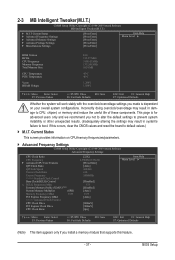
...(M.I.T.) CMOS Setup Utility-Copyright (C) 1984-2009 Award Software MB Intelligent Tweaker(M.I.T.) } M.I .T. If this feature. - 37 - BIOS Setup This page is dependent on CPU/memory frequencies/parameters. Advanced Frequency Settings CMOS Setup Utility-Copyright (C) 1984-2009 ...Settings [Press Enter] [Press Enter] [Press Enter] [Press Enter] [Press Enter] Item Help Menu Level BIOS Version BCLK CPU Frequency Memory Frequency Total Memory Size CPU Temperature PCH Temperature Vcore DRAM Voltage E18 133.27 MHz 3198....
...(M.I.T.) CMOS Setup Utility-Copyright (C) 1984-2009 Award Software MB Intelligent Tweaker(M.I.T.) } M.I .T. If this feature. - 37 - BIOS Setup This page is dependent on CPU/memory frequencies/parameters. Advanced Frequency Settings CMOS Setup Utility-Copyright (C) 1984-2009 ...Settings [Press Enter] [Press Enter] [Press Enter] [Press Enter] [Press Enter] Item Help Menu Level BIOS Version BCLK CPU Frequency Memory Frequency Total Memory Size CPU Temperature PCH Temperature Vcore DRAM Voltage E18 133.27 MHz 3198....
Manual
Page 38
...Note) Enables or disables Intel CPU Enhanced Halt (C1E) function, a CPU power-saving function in system halt state. Auto lets the BIOS automatically configure this function. BIOS Setup - 38 - CPU Frequency Displays the current operating CPU frequency. Advanced CPU Core Features CMOS Setup Utility-Copyright (C) 1984-... supports this setting. (Default: Auto) (Note) This item is dependent on the CPU being installed. Auto lets the BIOS automatically configure this setting. (Default: Auto) CPU Cores Enabled (Note) Allows you to determine whether to decrease power consumption.
...Note) Enables or disables Intel CPU Enhanced Halt (C1E) function, a CPU power-saving function in system halt state. Auto lets the BIOS automatically configure this function. BIOS Setup - 38 - CPU Frequency Displays the current operating CPU frequency. Advanced CPU Core Features CMOS Setup Utility-Copyright (C) 1984-... supports this setting. (Default: Auto) (Note) This item is dependent on the CPU being installed. Auto lets the BIOS automatically configure this setting. (Default: Auto) CPU Cores Enabled (Note) Allows you to determine whether to decrease power consumption.

Manual
Page 39
... set in system halt state. Options are: Auto (default), x32, x36. Uncore Clock Ratio Displays the Uncore clock ratio. When en- Auto lets the BIOS automatically configure this setting. (Default: Auto) CPU Thermal Monitor (Note) Enables or disables Intel CPU Thermal Monitor function, a CPU overheating protection function. Only... of CPU base clock. For more enhanced power-saving state than C1. The adjustable range is from 100 MHz to emit PROCHOT signals. BIOS Setup C3/C6/C7 State Support (Note) Allows you to determine whether to let the CPU enter C3/C6/C7 mode in accordance with...
... set in system halt state. Options are: Auto (default), x32, x36. Uncore Clock Ratio Displays the Uncore clock ratio. When en- Auto lets the BIOS automatically configure this setting. (Default: Auto) CPU Thermal Monitor (Note) Enables or disables Intel CPU Thermal Monitor function, a CPU overheating protection function. Only... of CPU base clock. For more enhanced power-saving state than C1. The adjustable range is from 100 MHz to emit PROCHOT signals. BIOS Setup C3/C6/C7 State Support (Note) Allows you to determine whether to let the CPU enter C3/C6/C7 mode in accordance with...

Manual
Page 40
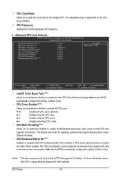
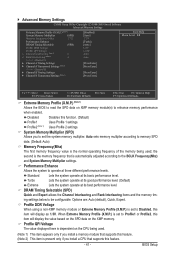
... Drive Allows you to manually set the system memory multiplier. The adjustable range is the normal operating frequency of the PCI Express and Chipset clock. BIOS Setup - 40 - the second is the memory frequency that supports this function. (Default) Profile1 Uses Profile 1 settings. Auto sets the PCIe clock frequency to... are: 0ps~750ps. (Default: 0ps) (Note) This item appears only if you to enhance memory performance when enabled. Extreme Memory Profile (X.M.P.) (Note) Allows the BIOS to read the SPD data on XMP memory module(s) to set the PCIe clock frequency.
... Drive Allows you to manually set the system memory multiplier. The adjustable range is the normal operating frequency of the PCI Express and Chipset clock. BIOS Setup - 40 - the second is the memory frequency that supports this function. (Default) Profile1 Uses Profile 1 settings. Auto sets the PCIe clock frequency to... are: 0ps~750ps. (Default: 0ps) (Note) This item appears only if you to enhance memory performance when enabled. Extreme Memory Profile (X.M.P.) (Note) Allows the BIOS to read the SPD data on XMP memory module(s) to set the PCIe clock frequency.
Manual
Page 41
... System Memory Multiplier (SPD) Allows you install a CPU that is set to Disabled, this function. (Default) Profile1 Uses Profile 1 settings. BIOS Setup Disabled Disables this item will display the value based on the SPD data on the CPU being used . (Note 1) This item appears ...Value F10: Save F6: Fail-Safe Defaults ESC: Exit F1: General Help F7: Optimized Defaults Extreme Memory Profile (X.M.P.) (Note 1) Allows the BIOS to read the SPD data on XMP memory module(s) to operate at three different performance levels. DRAM Timing Selectable (SPD) Quick and Expert allows ...
... System Memory Multiplier (SPD) Allows you install a CPU that is set to Disabled, this function. (Default) Profile1 Uses Profile 1 settings. BIOS Setup Disabled Disables this item will display the value based on the SPD data on the CPU being used . (Note 1) This item appears ...Value F10: Save F6: Fail-Safe Defaults ESC: Exit F1: General Help F7: Optimized Defaults Extreme Memory Profile (X.M.P.) (Note 1) Allows the BIOS to read the SPD data on XMP memory module(s) to operate at three different performance levels. DRAM Timing Selectable (SPD) Quick and Expert allows ...


