Manual
Page 3
... your motherboard looks like this manual is protected by any means without prior notice. Disclaimer Information in the use GIGABYTE's unique features, read the Quick Installation Guide included with the product. Documentation Classifications In order to the specifications and... page on your motherboard revision before updating motherboard BIOS, drivers, or when looking for technical information. All rights reserved. No part of this product, GIGABYTE provides the following types of documentations: For quick set-up of GIGABYTE. Example: Changes to assist in this : ...
... your motherboard looks like this manual is protected by any means without prior notice. Disclaimer Information in the use GIGABYTE's unique features, read the Quick Installation Guide included with the product. Documentation Classifications In order to the specifications and... page on your motherboard revision before updating motherboard BIOS, drivers, or when looking for technical information. All rights reserved. No part of this product, GIGABYTE provides the following types of documentations: For quick set-up of GIGABYTE. Example: Changes to assist in this : ...
Manual
Page 4
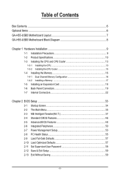
Table of Contents Box Contents...6 Optional Items...6 GA-H55-USB3 Motherboard Layout 7 GA-H55-USB3 Motherboard Block Diagram 8 Chapter 1 Hardware Installation 9 1-1 Installation Precautions 9 1-2 Product Specifications 10 1-3 Installing the CPU and CPU ... an Expansion Card 18 1-6 Back Panel Connectors 19 1-7 Internal Connectors 22 Chapter 2 BIOS Setup 33 2-1 Startup Screen 34 2-2 The Main Menu 35 2-3 MB Intelligent Tweaker(M.I.T 37 2-4 Standard CMOS Features 46 2-5 Advanced BIOS Features 48 2-6 Integrated Peripherals 50 2-7 Power Management Setup 53 2-8 PC Health Status ...
Table of Contents Box Contents...6 Optional Items...6 GA-H55-USB3 Motherboard Layout 7 GA-H55-USB3 Motherboard Block Diagram 8 Chapter 1 Hardware Installation 9 1-1 Installation Precautions 9 1-2 Product Specifications 10 1-3 Installing the CPU and CPU ... an Expansion Card 18 1-6 Back Panel Connectors 19 1-7 Internal Connectors 22 Chapter 2 BIOS Setup 33 2-1 Startup Screen 34 2-2 The Main Menu 35 2-3 MB Intelligent Tweaker(M.I.T 37 2-4 Standard CMOS Features 46 2-5 Advanced BIOS Features 48 2-6 Integrated Peripherals 50 2-7 Power Management Setup 53 2-8 PC Health Status ...

Manual
Page 5
...Download Center 64 3-7 New Utilities...64 Chapter 4 Unique Features 65 4-1 Xpress Recovery2 65 4-2 BIOS Update Utilities 68 4-2-1 Updating the BIOS with the Q-Flash Utility 68 4-2-2 Updating the BIOS with the @BIOS Utility 71 4-3 EasyTune 6...72 4-4 Dynamic Energy Saver™ 2 73 4-5 Q-Share...75 ...4-6 Smart 6™ ...76 4-7 Auto Green...79 Chapter 5 Appendix...81 5-1 Configuring SATA Hard Drive(s 81 5-1-1 Configuring GIGABYTE...
...Download Center 64 3-7 New Utilities...64 Chapter 4 Unique Features 65 4-1 Xpress Recovery2 65 4-2 BIOS Update Utilities 68 4-2-1 Updating the BIOS with the Q-Flash Utility 68 4-2-2 Updating the BIOS with the @BIOS Utility 71 4-3 EasyTune 6...72 4-4 Dynamic Energy Saver™ 2 73 4-5 Q-Share...75 ...4-6 Smart 6™ ...76 4-7 Auto Green...79 Chapter 5 Appendix...81 5-1 Configuring SATA Hard Drive(s 81 5-1-1 Configuring GIGABYTE...
Manual
Page 8
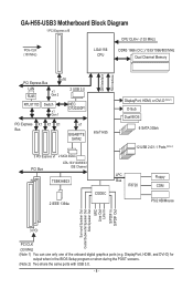
GA-H55-USB3 Motherboard Block Diagram 1 PCI Express x16 CPU CLK+/- (133 MHz) PCIe CLK (100 MHz) LGA1156 CPU DDR3...Bus LAN RJ45 x16 x1 Gen 2 2 USB 3.0 RTL8111D Switch x1 Gen 1 NEC D720200F1 PCI Express X1 X1 X1 Bus x1 GIGABYTE SATA2 Intel® H55 3 PCI Express x1 2 SATA 3Gb/s PCI Bus ATA-133/100/66/33 IDE Channel TSB43AB23 2 IEEE 1394a CODEC DisplayPort, HDMI...can use only one of the onboard digital graphics ports (e.g. DisplayPort, HDMI, and DVI-D) for output when in the BIOS Setup program or when during the POST screens. (Note 2) Two share the same ports with USB 3.0. - 8 -
GA-H55-USB3 Motherboard Block Diagram 1 PCI Express x16 CPU CLK+/- (133 MHz) PCIe CLK (100 MHz) LGA1156 CPU DDR3...Bus LAN RJ45 x16 x1 Gen 2 2 USB 3.0 RTL8111D Switch x1 Gen 1 NEC D720200F1 PCI Express X1 X1 X1 Bus x1 GIGABYTE SATA2 Intel® H55 3 PCI Express x1 2 SATA 3Gb/s PCI Bus ATA-133/100/66/33 IDE Channel TSB43AB23 2 IEEE 1394a CODEC DisplayPort, HDMI...can use only one of the onboard digital graphics ports (e.g. DisplayPort, HDMI, and DVI-D) for output when in the BIOS Setup program or when during the POST screens. (Note 2) Two share the same ports with USB 3.0. - 8 -

Manual
Page 12
...w w w w Bundled Software w 2 x 64 Mbit flash Use of licensed AWARD BIOS Support for DualBIOS™ PnP 1.0a, DMI 2.0, SM BIOS 2.4, ACPI 1.0b Support for @BIOS Support for Q-Flash Support for Xpress BIOS Rescue Support for Download Center Support for Xpress Install Support for Xpress Recovery2 Support for EasyTune ...Support for Auto Green Support for Q-Share Norton Internet Security (OEM version) Operating System w Support for output when in the BIOS Setup program or when during the POST screens. (Note 5) Two share the same ports with integrated graphics. (Note 3) The...
...w w w w Bundled Software w 2 x 64 Mbit flash Use of licensed AWARD BIOS Support for DualBIOS™ PnP 1.0a, DMI 2.0, SM BIOS 2.4, ACPI 1.0b Support for @BIOS Support for Q-Flash Support for Xpress BIOS Rescue Support for Download Center Support for Xpress Install Support for Xpress Recovery2 Support for EasyTune ...Support for Auto Green Support for Q-Share Norton Internet Security (OEM version) Operating System w Support for output when in the BIOS Setup program or when during the POST screens. (Note 5) Two share the same ports with integrated graphics. (Note 3) The...
Manual
Page 16
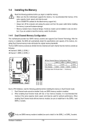
... memory: • Make sure that the motherboard supports the memory. Dual Channel mode cannot be enabled if only one DDR3 memory module is installed, the BIOS will double the original memory bandwidth. If only one direction. Hardware Installation - 16 - After the memory is installed. 2. 1-4 Installing the Memory Read the following guidelines... Dual Channel Technology. If you begin to install it is recommended that memory of the same capacity, brand, speed, and chips be used . (Go to GIGABYTE's website for optimum performance.
... memory: • Make sure that the motherboard supports the memory. Dual Channel mode cannot be enabled if only one DDR3 memory module is installed, the BIOS will double the original memory bandwidth. If only one direction. Hardware Installation - 16 - After the memory is installed. 2. 1-4 Installing the Memory Read the following guidelines... Dual Channel Technology. If you begin to install it is recommended that memory of the same capacity, brand, speed, and chips be used . (Go to GIGABYTE's website for optimum performance.
Manual
Page 18
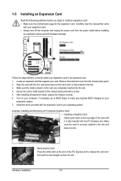
PCI Express x1 Slot PCI Express x16 Slot PCI Slot Follow the steps below to make any required BIOS changes for your expansion card in the slot and does not rock. • Removing the Card: Press the white latch at the end of the ...card until it is fully inserted into the slot. 4. If necessary, go to BIOS Setup to correctly install your expansion card(s). 7. Install the driver provided with the expansion card in the slot. 3. Example: Installing and Removing a PCI Express Graphics...
PCI Express x1 Slot PCI Express x16 Slot PCI Slot Follow the steps below to make any required BIOS changes for your expansion card in the slot and does not rock. • Removing the Card: Press the white latch at the end of the ...card until it is fully inserted into the slot. 4. If necessary, go to BIOS Setup to correctly install your expansion card(s). 7. Install the driver provided with the expansion card in the slot. 3. Example: Installing and Removing a PCI Express Graphics...
Manual
Page 20
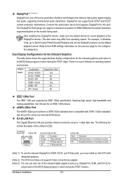
...interface technologies that supports DisplayPort to 1 Gbps data rate. DisplayPort, HDMI, and DVI-D) for the onboard graphics ports when in the BIOS Setup program or when during the POST stage. DisplayPort can support a maximum resolution of 2560x1600p but the actual resolutions supported depend on... box.) Dual Display Configurations for the Onboard Graphics: The table below shows the supported dual display configurations for output when in the BIOS Setup program or when during the POST screens. Refer to SATA 3Gb/s standard and is compatible with integrated graphics. (Note 2) The...
...interface technologies that supports DisplayPort to 1 Gbps data rate. DisplayPort, HDMI, and DVI-D) for the onboard graphics ports when in the BIOS Setup program or when during the POST stage. DisplayPort can support a maximum resolution of 2560x1600p but the actual resolutions supported depend on... box.) Dual Display Configurations for the Onboard Graphics: The table below shows the supported dual display configurations for output when in the BIOS Setup program or when during the POST screens. Refer to SATA 3Gb/s standard and is compatible with integrated graphics. (Note 2) The...
Manual
Page 26
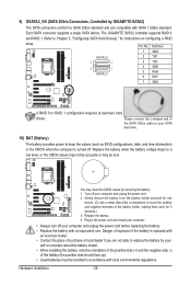
... at least two hard drives. Turn off your SATA hard drive. 10) BAT (Battery) The battery provides power to keep the values (such as BIOS configurations, date, and time information) in the CMOS when the computer is replaced with an incorrect model. • Contact the place of purchase or ...local dealer if you are not able to replace the battery by GIGABYTE SATA2) The SATA connectors conform to SATA 3Gb/s standard and are compatible with SATA 1.5Gb/s standard. Please connect the L-shaped end of the battery...
... at least two hard drives. Turn off your SATA hard drive. 10) BAT (Battery) The battery provides power to keep the values (such as BIOS configurations, date, and time information) in the CMOS when the computer is replaced with an incorrect model. • Contact the place of purchase or ...local dealer if you are not able to replace the battery by GIGABYTE SATA2) The SATA connectors conform to SATA 3Gb/s standard and are compatible with SATA 1.5Gb/s standard. Please connect the L-shaped end of the battery...
Manual
Page 27
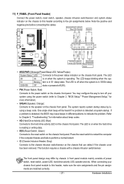
... to the power status indicator on the chassis front panel. If a problem is operating. When connecting your system using the power switch (refer to Chapter 2, "BIOS Setup," "Power Management Setup," for information about beep codes. • HD (Hard Drive Activity LED, Blue) Connects to the chassis intrusion switch/sensor on the..., make sure the wire assignments and the pin assignments are matched correctly. - 27 - The LED S0 On is on when the system is detected, the BIOS may issue beeps in S1 sleep state.
... to the power status indicator on the chassis front panel. If a problem is operating. When connecting your system using the power switch (refer to Chapter 2, "BIOS Setup," "Power Management Setup," for information about beep codes. • HD (Hard Drive Activity LED, Blue) Connects to the chassis intrusion switch/sensor on the..., make sure the wire assignments and the pin assignments are matched correctly. - 27 - The LED S0 On is on when the system is detected, the BIOS may issue beeps in S1 sleep state.
Manual
Page 31
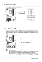
... Pin No. Failure to do so may cause damage to the motherboard. • After system restart, go to BIOS Setup to load factory defaults (select Load Optimized Defaults) or manually configure the BIOS settings (refer to factory defaults. Open: Normal Short: Clear CMOS Values • Always turn off your computer, be...before turning on the two pins to temporarily short the two pins or use a metal object like a screwdriver to touch the two pins for BIOS configurations). - 31 - To clear the CMOS values, place a jumper cap on your computer and unplug the power cord from the jumper.
... Pin No. Failure to do so may cause damage to the motherboard. • After system restart, go to BIOS Setup to load factory defaults (select Load Optimized Defaults) or manually configure the BIOS settings (refer to factory defaults. Open: Normal Short: Clear CMOS Values • Always turn off your computer, be...before turning on the two pins to temporarily short the two pins or use a metal object like a screwdriver to touch the two pins for BIOS configurations). - 31 - To clear the CMOS values, place a jumper cap on your computer and unplug the power cord from the jumper.
Manual
Page 33
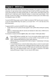
... program, press the key during system startup, saving system parameters and loading operating system, etc. BIOS Setup For instructions on . Refer to Chapter 5, "Troubleshooting," for how to boot. To upgrade the BIOS, use either the GIGABYTE Q-Flash or @BIOS utility. • Q-Flash allows the user to prevent system instability or other unexpected results. Chapter...
... program, press the key during system startup, saving system parameters and loading operating system, etc. BIOS Setup For instructions on . Refer to Chapter 5, "Troubleshooting," for how to boot. To upgrade the BIOS, use either the GIGABYTE Q-Flash or @BIOS utility. • Q-Flash allows the user to prevent system instability or other unexpected results. Chapter...
Manual
Page 34
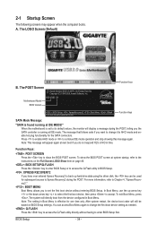
... select the first boot device, then press to access the Q-Flash utility directly without entering BIOS Setup. The system will appear again at IDE MODE!" Motherboard Model BIOS Version H55-USB3 E4 . . . . : BIOS Setup : XpressRecovery2 : Boot Menu : Qflash 01/10/2010-H55-7A89TG0TC-00 Function Keys Function Keys SATA Mode Message: "SATA is running at next...
... select the first boot device, then press to access the Q-Flash utility directly without entering BIOS Setup. The system will appear again at IDE MODE!" Motherboard Model BIOS Version H55-USB3 E4 . . . . : BIOS Setup : XpressRecovery2 : Boot Menu : Qflash 01/10/2010-H55-7A89TG0TC-00 Function Keys Function Keys SATA Mode Message: "SATA is running at next...

Manual
Page 35
... Save & Exit Setup Exit Without Saving ESC: Quit F8: Q-Flash Select Item F10: Save & Exit Setup Change CPU's Clock & Voltage F11: Save CMOS to BIOS F12: Load CMOS from BIOS BIOS Setup Program Function Keys Move the selection bar to select an item Execute command or enter the submenu Main Menu: Exit the... item is in the Item Help block on the right side of the Main Menu. Submenu Help While in a submenu, press to display a help screen. BIOS Setup 2-2 The Main Menu Once you want in the Main Menu or a submenu, press + to access more advanced options. • When the system is not...
... Save & Exit Setup Exit Without Saving ESC: Quit F8: Q-Flash Select Item F10: Save & Exit Setup Change CPU's Clock & Voltage F11: Save CMOS to BIOS F12: Load CMOS from BIOS BIOS Setup Program Function Keys Move the selection bar to select an item Execute command or enter the submenu Main Menu: Exit the... item is in the Item Help block on the right side of the Main Menu. Submenu Help While in a submenu, press to display a help screen. BIOS Setup 2-2 The Main Menu Once you want in the Main Menu or a submenu, press + to access more advanced options. • When the system is not...
Manual
Page 36
... time and date, hard drive types, floppy disk drive types, and the type of errors that stop the system boot, etc. Advanced BIOS Features Use this menu to configure the device boot order, advanced features available on the CPU, and the primary display adapter. Integrated Peripherals ...can use the SPACE key) and then press to complete. F12: Load CMOS from a profile created before, without the hassles of reconfiguring the BIOS settings. It allows you to make changes. Save & Exit Setup Save all the changes made in effect. It allows you to save the ...
... time and date, hard drive types, floppy disk drive types, and the type of errors that stop the system boot, etc. Advanced BIOS Features Use this menu to configure the device boot order, advanced features available on the CPU, and the primary display adapter. Integrated Peripherals ...can use the SPACE key) and then press to complete. F12: Load CMOS from a profile created before, without the hassles of reconfiguring the BIOS settings. It allows you to make changes. Save & Exit Setup Save all the changes made in effect. It allows you to save the ...

Manual
Page 37
... Voltage Settings } Miscellaneous Settings [Press Enter] [Press Enter] [Press Enter] [Press Enter] [Press Enter] Item Help Menu Level BIOS Version BCLK CPU Frequency Memory Frequency Total Memory Size E4 133.37 MHz 3067.78 MHz 1333.75 MHz 1024 MB CPU Temperature PCH Temperature...CPUs' unique features, please visit Intel's website. (Note 2) This item appears only if you install a CPU that supports this feature. BIOS Setup If this occurs, clear the CMOS values and reset the board to CPU, chipset, or memory and reduce the useful life of these...
... Voltage Settings } Miscellaneous Settings [Press Enter] [Press Enter] [Press Enter] [Press Enter] [Press Enter] Item Help Menu Level BIOS Version BCLK CPU Frequency Memory Frequency Total Memory Size E4 133.37 MHz 3067.78 MHz 1333.75 MHz 1024 MB CPU Temperature PCH Temperature...CPUs' unique features, please visit Intel's website. (Note 2) This item appears only if you install a CPU that supports this feature. BIOS Setup If this occurs, clear the CMOS values and reset the board to CPU, chipset, or memory and reduce the useful life of these...
Manual
Page 38
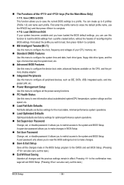
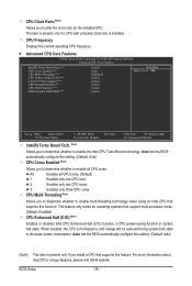
...cores. 3 Enables only three CPU cores. CPU Multi-Threading (Note) Allows you to determine whether to enable the Intel CPU Turbo Boost technology. BIOS Setup - 38 - CPU Frequency Displays the current operating CPU frequency. Advanced CPU Core Features CMOS Setup Utility-Copyright (C) 1984-2009 ...only if you to enable multi-threading technology when using an Intel CPU that supports this function. Auto lets the BIOS automatically configure this setting. (Default: Auto) CPU Cores Enabled (Note) Allows you to determine whether to decrease power consumption. Auto lets ...
...cores. 3 Enables only three CPU cores. CPU Multi-Threading (Note) Allows you to determine whether to enable the Intel CPU Turbo Boost technology. BIOS Setup - 38 - CPU Frequency Displays the current operating CPU frequency. Advanced CPU Core Features CMOS Setup Utility-Copyright (C) 1984-2009 ...only if you to enable multi-threading technology when using an Intel CPU that supports this function. Auto lets the BIOS automatically configure this setting. (Default: Auto) CPU Cores Enabled (Note) Allows you to determine whether to decrease power consumption. Auto lets ...
Manual
Page 39
... is occurring to emit PROCHOT signals. Important: It is highly recommended that the CPU frequency be configurable. Auto lets the BIOS automatically configure this setting. (Default) When the CPU or chipset detects that an overheating is occurring, PROCHOT signals will allow... this feature. Depending on the CPU being used. ting. (Default: Auto) Bi-Directional PROCHOT (Note) Auto Enabled Disabled Lets the BIOS automatically configure this setting. (Default: Auto) CPU EIST Function (Note) Enables or disables Enhanced Intel SpeedStep Technology (EIST). abled, the...
... is occurring to emit PROCHOT signals. Important: It is highly recommended that the CPU frequency be configurable. Auto lets the BIOS automatically configure this setting. (Default) When the CPU or chipset detects that an overheating is occurring, PROCHOT signals will allow... this feature. Depending on the CPU being used. ting. (Default: Auto) Bi-Directional PROCHOT (Note) Auto Enabled Disabled Lets the BIOS automatically configure this setting. (Default: Auto) CPU EIST Function (Note) Enables or disables Enhanced Intel SpeedStep Technology (EIST). abled, the...

Manual
Page 40
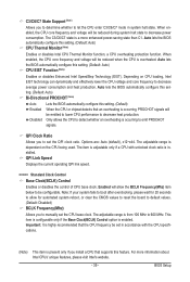
... Skew Allows you to memory SPD data. (Default: Auto) Memory Frequency(Mhz) The first memory frequency value is automatically adjusted according to the Chipset clock. BIOS Setup - 40 - Profile2 (Note) Uses Profile 2 settings. PCI Express Frequency(Mhz) Allows you to set the PCIe clock frequency. Options are : 0ps~750ps. (Default: 0ps... appears only if you install a memory module that is the normal operating frequency of the CPU and Chipset clock. Extreme Memory Profile (X.M.P.) (Note) Allows the BIOS to read the SPD data on XMP memory module(s) to 150 MHz.
... Skew Allows you to memory SPD data. (Default: Auto) Memory Frequency(Mhz) The first memory frequency value is automatically adjusted according to the Chipset clock. BIOS Setup - 40 - Profile2 (Note) Uses Profile 2 settings. PCI Express Frequency(Mhz) Allows you to set the PCIe clock frequency. Options are : 0ps~750ps. (Default: 0ps... appears only if you install a memory module that is the normal operating frequency of the CPU and Chipset clock. Extreme Memory Profile (X.M.P.) (Note) Allows the BIOS to read the SPD data on XMP memory module(s) to 150 MHz.

Manual
Page 41
... at its basic performance level. Options are synchronous to Disabled, this item will display the value based on the SPD data on the XMP memory. BIOS Setup Performance Enhance Allows the system to be configurable. DRAM Timing Selectable (SPD) Quick and Expert allows the Channel Interleaving and Rank Interleaving items to...
... at its basic performance level. Options are synchronous to Disabled, this item will display the value based on the SPD data on the XMP memory. BIOS Setup Performance Enhance Allows the system to be configurable. DRAM Timing Selectable (SPD) Quick and Expert allows the Channel Interleaving and Rank Interleaving items to...


