Manual
Page 3
...X.X." Example: Disclaimer Information in any form or by any means without prior notice. The trademarks mentioned in the use GIGABYTE's unique features, read or download the information on/from the Support&Downloads\Motherboard\Technology Guide page on our website. ... manual is protected by GIGABYTE without GIGABYTE's prior written permission. Changes to use of documentations: For detailed product information, carefully read the User's Manual. For instructions on your motherboard revision before updating motherboard BIOS, drivers, or when looking...
...X.X." Example: Disclaimer Information in any form or by any means without prior notice. The trademarks mentioned in the use GIGABYTE's unique features, read or download the information on/from the Support&Downloads\Motherboard\Technology Guide page on our website. ... manual is protected by GIGABYTE without GIGABYTE's prior written permission. Changes to use of documentations: For detailed product information, carefully read the User's Manual. For instructions on your motherboard revision before updating motherboard BIOS, drivers, or when looking...
Manual
Page 4
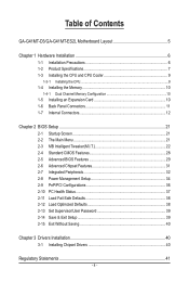
Table of Contents GA-G41MT-D3/GA-G41MT-ES2L Motherboard Layout 5 Chapter 1 Hardware Installation 6 1-1 Installation Precautions 6 1-2 Product Specifications 7 1-3 Installing the CPU and CPU Cooler 9 1-3-1 Installing the CPU...9 1-4 Installing the Memory 10 1-4-1 Dual Channel Memory Configuration 10 1-5 Installing an Expansion Card 10 1-6 Back Panel Connectors 11 1-7 Internal Connectors 12 Chapter 2 BIOS Setup 21 2-1 Startup Screen 21 2-2 The Main...
Table of Contents GA-G41MT-D3/GA-G41MT-ES2L Motherboard Layout 5 Chapter 1 Hardware Installation 6 1-1 Installation Precautions 6 1-2 Product Specifications 7 1-3 Installing the CPU and CPU Cooler 9 1-3-1 Installing the CPU...9 1-4 Installing the Memory 10 1-4-1 Dual Channel Memory Configuration 10 1-5 Installing an Expansion Card 10 1-6 Back Panel Connectors 11 1-7 Internal Connectors 12 Chapter 2 BIOS Setup 21 2-1 Startup Screen 21 2-2 The Main...
Manual
Page 8
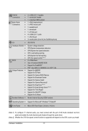
... w 1 x PS/2 mouse port w 1 x parallel port w 1 x serial port w 1 x D-Sub port w 4 x USB 2.0/1.1 ports w 1 x RJ-45 port w 3 x audio jacks (Line In/Line Out/Microphone) I/O w iTE IT8718 Hardware Monitor w w w w w w BIOS w w w w Unique Features w w w w w w w w w w w System voltage detection CPU/System temperature detection CPU/System fan speed detection CPU overheating warning CPU/System fan fail warning CPU fan speed...
... w 1 x PS/2 mouse port w 1 x parallel port w 1 x serial port w 1 x D-Sub port w 4 x USB 2.0/1.1 ports w 1 x RJ-45 port w 3 x audio jacks (Line In/Line Out/Microphone) I/O w iTE IT8718 Hardware Monitor w w w w w w BIOS w w w w Unique Features w w w w w w w w w w w System voltage detection CPU/System temperature detection CPU/System fan speed detection CPU overheating warning CPU/System fan fail warning CPU fan speed...
Manual
Page 10
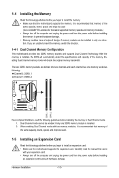
... guidelines before you begin to install an expansion card: • Make sure the motherboard supports the expansion card. It is installed, the BIOS will double the original memory bandwidth. Enabling Dual Channel memory mode will automatically detect the specifications and capacity of the same capacity, brand, ...speed, and chips be enabled if only one direction. Dual Channel mode cannot be used . (Go to GIGABYTE's website for the latest supported memory speeds and memory modules.) • Always turn off the computer and unplug the power cord from the ...
... guidelines before you begin to install an expansion card: • Make sure the motherboard supports the expansion card. It is installed, the BIOS will double the original memory bandwidth. Enabling Dual Channel memory mode will automatically detect the specifications and capacity of the same capacity, brand, ...speed, and chips be enabled if only one direction. Dual Channel mode cannot be used . (Go to GIGABYTE's website for the latest supported memory speeds and memory modules.) • Always turn off the computer and unplug the power cord from the ...
Manual
Page 16
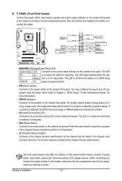
... activity LED, speaker and etc. Hardware Installation - 16 - You may configure the way to turn off when the system is detected, the BIOS may differ by issuing a beep code. If a problem is in S1 sleep state. When connecting your system using the power switch (refer to Chapter... 2, "BIOS Setup," "Power Management Setup," for more information). • SPEAK (Speaker): Connects to the hard drive activity LED on the chassis front panel. HD...
... activity LED, speaker and etc. Hardware Installation - 16 - You may configure the way to turn off when the system is detected, the BIOS may differ by issuing a beep code. If a problem is in S1 sleep state. When connecting your system using the power switch (refer to Chapter... 2, "BIOS Setup," "Power Management Setup," for more information). • SPEAK (Speaker): Connects to the hard drive activity LED on the chassis front panel. HD...
Manual
Page 19
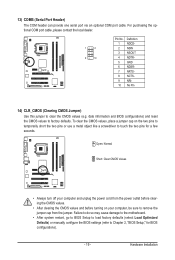
... 1 2 9 10 Pin No. 1 2 3 4 5 6 7 8 9 10 Definition NDCDNSIN NSOUT NDTRGND NDSRNRTSNCTSNRINo Pin 14) CLR_CMOS (Clearing CMOS Jumper) Use this jumper to Chapter 2, "BIOS Setup," for a few seconds. Failure to do so may cause damage to the motherboard. • After system restart, go to... to load factory defaults (select Load Optimized Defaults) or manually configure the BIOS settings (refer to clear the CMOS values (e.g. date information and BIOS configurations) and reset the CMOS values to touch the two pins for BIOS configurations). - 19 - 13) COMB (Serial Port Header) The COM ...
... 1 2 9 10 Pin No. 1 2 3 4 5 6 7 8 9 10 Definition NDCDNSIN NSOUT NDTRGND NDSRNRTSNCTSNRINo Pin 14) CLR_CMOS (Clearing CMOS Jumper) Use this jumper to Chapter 2, "BIOS Setup," for a few seconds. Failure to do so may cause damage to the motherboard. • After system restart, go to... to load factory defaults (select Load Optimized Defaults) or manually configure the BIOS settings (refer to clear the CMOS values (e.g. date information and BIOS configurations) and reset the CMOS values to touch the two pins for BIOS configurations). - 19 - 13) COMB (Serial Port Header) The COM ...
Manual
Page 20
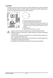
... battery with an incorrect model. • Contact the place of purchase or local dealer if you are not able to keep the values (such as BIOS configurations, date, and time information) in the power cord and restart your computer. • Always turn off your computer and unplug the power cord. 2. Danger...
... battery with an incorrect model. • Contact the place of purchase or local dealer if you are not able to keep the values (such as BIOS configurations, date, and time information) in the power cord and restart your computer. • Always turn off your computer and unplug the power cord. 2. Danger...
Manual
Page 21
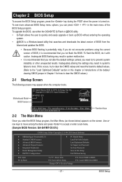
To upgrade the BIOS, use either the GIGABYTE Q-Flash or @BIOS utility. • Q-Flash allows the user to clear the CMOS values.) 2-1 Startup Screen The following screens may appear when the computer boots. If this... keys to move among the items and press to accept or enter a sub-menu. (Sample BIOS Version: GA-G41MT-D3 E7c) CMOS Setup Utility-Copyright (C) 1984-2010 Award Software MB Intelligent Tweaker(M.I.T.) Standard CMOS Features Advanced BIOS Features Advanced Chipset Features Integrated Peripherals Power Management Setup ...
To upgrade the BIOS, use either the GIGABYTE Q-Flash or @BIOS utility. • Q-Flash allows the user to clear the CMOS values.) 2-1 Startup Screen The following screens may appear when the computer boots. If this... keys to move among the items and press to accept or enter a sub-menu. (Sample BIOS Version: GA-G41MT-D3 E7c) CMOS Setup Utility-Copyright (C) 1984-2010 Award Software MB Intelligent Tweaker(M.I.T.) Standard CMOS Features Advanced BIOS Features Advanced Chipset Features Integrated Peripherals Power Management Setup ...
Manual
Page 22
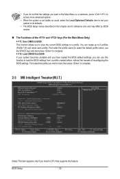
• If you do not find the settings you want in this chapter are for reference only and may differ by BIOS version. The Functions of reconfiguring the BIOS settings. You can use the SPACE key) and then press to complete. F12: Load CMOS from a profile created ...F7: Optimized Defaults (Note) This item appears only if you install a CPU that supports this function to load the BIOS settings from BIOS If your system to its defaults. • The BIOS Setup menus described in the Main Menu or a submenu, press + to access more advanced options. • When the...
• If you do not find the settings you want in this chapter are for reference only and may differ by BIOS version. The Functions of reconfiguring the BIOS settings. You can use the SPACE key) and then press to complete. F12: Load CMOS from a profile created ...F7: Optimized Defaults (Note) This item appears only if you install a CPU that supports this function to load the BIOS settings from BIOS If your system to its defaults. • The BIOS Setup menus described in the Main Menu or a submenu, press + to access more advanced options. • When the...

Manual
Page 23
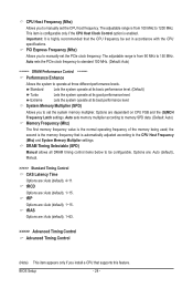
... enhance the performance of the graphics chip and memory. Options are: Auto (default), Fast, Turbo. BIOS Setup CMOS Setup Utility-Copyright (C) 1984-2010 Award Software MB Intelligent Tweaker(M.I.T.) x tRCD 9 x tRP 9 x tRAS 24 >>>>> Advanced Timing Control } Advanced Timing Control Auto Auto Auto [...
... enhance the performance of the graphics chip and memory. Options are: Auto (default), Fast, Turbo. BIOS Setup CMOS Setup Utility-Copyright (C) 1984-2010 Award Software MB Intelligent Tweaker(M.I.T.) x tRCD 9 x tRP 9 x tRAS 24 >>>>> Advanced Timing Control } Advanced Timing Control Auto Auto Auto [...
Manual
Page 24
... Frequency Latch settings. This item is configurable only if the CPU Host Clock Control option is the normal operating frequency of the memory being used; BIOS Setup - 24 - Important: It is from 90 MHz to 150 MHz. PCI Express Frequency (Mhz) Allows you to be set in accordance with the CPU...
... Frequency Latch settings. This item is configurable only if the CPU Host Clock Control option is the normal operating frequency of the memory being used; BIOS Setup - 24 - Important: It is from 90 MHz to 150 MHz. PCI Express Frequency (Mhz) Allows you to be set in accordance with the CPU...
Manual
Page 25
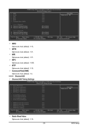
...: Previous Values +/-/PU/PD: Value F10: Save F6: Fail-Safe Defaults ESC: Exit F1: General Help F7: Optimized Defaults tRRD Options are : Auto (default), 1~255. BIOS Setup tWR Options are : Auto (default), 1~31. tWTR Options are : Auto (default), 1~31.
...: Previous Values +/-/PU/PD: Value F10: Save F6: Fail-Safe Defaults ESC: Exit F1: General Help F7: Optimized Defaults tRRD Options are : Auto (default), 1~255. BIOS Setup tWR Options are : Auto (default), 1~31. tWTR Options are : Auto (default), 1~31.
Manual
Page 26
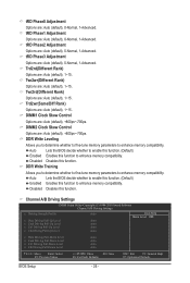
... F5: Previous Values +/-/PU/PD: Value F10: Save F6: Fail-Safe Defaults ESC: Exit F1: General Help F7: Optimized Defaults BIOS Setup - 26 - Twr2wr(Different Rank) Options are : Auto (default), +800ps~-700ps. DIMM2 Clock Skew Control Options are : Auto (default),...enable this function. (Default) Enabled Enables this function. DIMM1 Clock Skew Control Options are : Auto (default), 0-Normal, 1-Advanced. Auto Lets the BIOS decide whether to enhance memory compatibility. tRD Phase0 Adjustment Options are : Auto (default), 0-Normal, 1-Advanced. tRD Phase3 Adjustment Options are : Auto (...
... F5: Previous Values +/-/PU/PD: Value F10: Save F6: Fail-Safe Defaults ESC: Exit F1: General Help F7: Optimized Defaults BIOS Setup - 26 - Twr2wr(Different Rank) Options are : Auto (default), +800ps~-700ps. DIMM2 Clock Skew Control Options are : Auto (default),...enable this function. (Default) Enabled Enables this function. DIMM1 Clock Skew Control Options are : Auto (default), 0-Normal, 1-Advanced. Auto Lets the BIOS decide whether to enhance memory compatibility. tRD Phase0 Adjustment Options are : Auto (default), 0-Normal, 1-Advanced. tRD Phase3 Adjustment Options are : Auto (...
Manual
Page 27
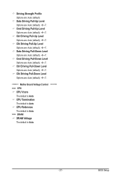
... Pull-Down Level Options are : Auto (default), +8~-7. Cmd Driving Pull-Up Level Options are : Auto (default), +8~-7. Cmd Driving Pull-Down Level Options are : Auto (default), +8~-7. BIOS Setup Ctrl Driving Pull-Up Level Options are : Auto (default), +8~-7. Ctrl Driving Pull-Down Level Options are: Auto (default), +8~-7.
... Pull-Down Level Options are : Auto (default), +8~-7. Cmd Driving Pull-Up Level Options are : Auto (default), +8~-7. Cmd Driving Pull-Down Level Options are : Auto (default), +8~-7. BIOS Setup Ctrl Driving Pull-Up Level Options are : Auto (default), +8~-7. Ctrl Driving Pull-Down Level Options are: Auto (default), +8~-7.
Manual
Page 28
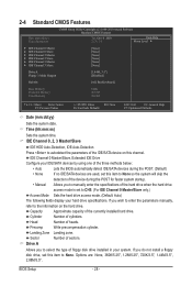
...floppy disk drive, set to select the type of floppy disk drive installed in your hard drive specifications. Capacity Approximate capacity of heads. BIOS Setup - 28 - Head Number of the currently installed hard drive. Precomp Write precompensation cylinder. Landing Zone Landing zone. If you to...drive when the hard drive access mode is set this item to autodetect the parameters of the three methods below: • Auto Lets the BIOS automatically detect IDE/SATA devices during the POST. (Default) • None If no IDE/SATA devices are : None, 360K/5.25", ...
...floppy disk drive, set to select the type of floppy disk drive installed in your hard drive specifications. Capacity Approximate capacity of heads. BIOS Setup - 28 - Head Number of the currently installed hard drive. Precomp Write precompensation cylinder. Landing Zone Landing zone. If you to...drive when the hard drive access mode is set this item to autodetect the parameters of the three methods below: • Auto Lets the BIOS automatically detect IDE/SATA devices during the POST. (Default) • None If no IDE/SATA devices are : None, 360K/5.25", ...
Manual
Page 29
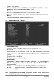
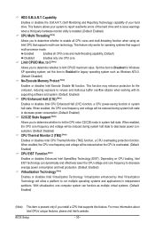
... Support (Note) CPU Thermal Monitor 2(TM2) (Note) CPU EIST Function (Note) Virtualization Technology (Note) Delay For HDD (Secs) Backup BIOS Image to specify whether the installed floppy disk drive is 3-mode floppy disk drive, a Japanese standard floppy disk drive. Password Check Specifies whether...All, But Keyboard" (default), "All, But Diskette," "All, But Disk/Key." Capability CPU Multi-Threading (Note) Limit CPUID Max. BIOS Setup Floppy 3 Mode Support Allows you install a CPU that supports this item, set the password(s) under the Set Supervisor/User Password item in...
... Support (Note) CPU Thermal Monitor 2(TM2) (Note) CPU EIST Function (Note) Virtualization Technology (Note) Delay For HDD (Secs) Backup BIOS Image to specify whether the installed floppy disk drive is 3-mode floppy disk drive, a Japanese standard floppy disk drive. Password Check Specifies whether...All, But Keyboard" (default), "All, But Diskette," "All, But Disk/Key." Capability CPU Multi-Threading (Note) Limit CPUID Max. BIOS Setup Floppy 3 Mode Support Allows you install a CPU that supports this item, set the password(s) under the Set Supervisor/User Password item in...
Manual
Page 30
... CPU loading, Intel EIST technology can function as Windows NT4.0. (Default: Disabled) No-Execute Memory Protect (Note) Enables or disables Intel Execute Disable Bit function. BIOS Setup - 30 -
... CPU loading, Intel EIST technology can function as Windows NT4.0. (Default: Disabled) No-Execute Memory Protect (Note) Enables or disables Intel Execute Disable Bit function. BIOS Setup - 30 -
Manual
Page 31
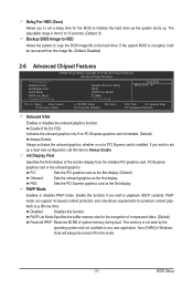
PCI Sets the PCI graphics card as the first display. (Default) Onboard Sets the onboard graphics as the first display. If the system BIOS is installed. PAVP Lite Mode Specifies the buffer memory size for premium content playback (e.g. If you wish to set up a dual view configuration, ...set a delay time for the BIOS to initialize the hard drive as the system boots up. PEG Sets the PCI Express graphics card as the first display. Disabled Disables this function...
PCI Sets the PCI graphics card as the first display. (Default) Onboard Sets the onboard graphics as the first display. If the system BIOS is installed. PAVP Lite Mode Specifies the buffer memory size for premium content playback (e.g. If you wish to set up a dual view configuration, ...set a delay time for the BIOS to initialize the hard drive as the system boots up. PEG Sets the PCI Express graphics card as the first display. Disabled Disables this function...
Manual
Page 32
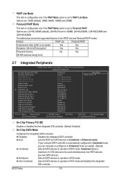
...-Chip SATA Mode x PATA IDE Set to SATA Port 0/2 Set to SATA Port 1/3 Set to Combined or Enhanced mode. Auto Lets the BIOS set SATA devices to Azalia Codec Onboard H/W LAN Green LAN } SMART LAN Onboard LAN Boot ROM Onboard Serial Port 1 Onboard Serial Port 2... Enhanced mode as needed. (Default) Combined Sets all SATA devices to Paranoid PAVP. Enhanced Sets all SATA devices to operate in SATA mode. BIOS Setup - 32 - Disabled Disables the integrated SATA controller. The table below shows the supported features of 4 ATA devices to 160MB, (64+...
...-Chip SATA Mode x PATA IDE Set to SATA Port 0/2 Set to SATA Port 1/3 Set to Combined or Enhanced mode. Auto Lets the BIOS set SATA devices to Azalia Codec Onboard H/W LAN Green LAN } SMART LAN Onboard LAN Boot ROM Onboard Serial Port 1 Onboard Serial Port 2... Enhanced mode as needed. (Default) Combined Sets all SATA devices to Paranoid PAVP. Enhanced Sets all SATA devices to operate in SATA mode. BIOS Setup - 32 - Disabled Disables the integrated SATA controller. The table below shows the supported features of 4 ATA devices to 160MB, (64+...

Manual
Page 33
...: Auto) If you wish to install a 3rd party add-in network card instead of using the onboard audio, set this item to Ch. 1 Master/Slave. BIOS Setup PATA IDE Set to This item is configurable only if the On-Chip SATA Mode is set to Disabled. Part1-2 Status = Open / Length = 0m...
...: Auto) If you wish to install a 3rd party add-in network card instead of using the onboard audio, set this item to Ch. 1 Master/Slave. BIOS Setup PATA IDE Set to This item is configurable only if the On-Chip SATA Mode is set to Disabled. Part1-2 Status = Open / Length = 0m...


