Manual
Page 3
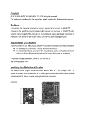
... information, carefully read the User's Manual. For instructions on how to the specifications and features in this product, GIGABYTE provides the following types of the motherboard is the property of this manual are legally registered to assist in the use GIGABYTE's unique features, read or download the information on/from the Support&Downloads\Motherboard\Technology Guide page on your motherboard revision before updating motherboard BIOS, drivers, or when looking for...
... information, carefully read the User's Manual. For instructions on how to the specifications and features in this product, GIGABYTE provides the following types of the motherboard is the property of this manual are legally registered to assist in the use GIGABYTE's unique features, read or download the information on/from the Support&Downloads\Motherboard\Technology Guide page on your motherboard revision before updating motherboard BIOS, drivers, or when looking for...
Manual
Page 4
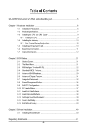
... of Contents GA-G41MT-D3/GA-G41MT-ES2L Motherboard Layout 5 Chapter 1 Hardware Installation 6 1-1 Installation Precautions 6 1-2 Product Specifications 7 1-3 Installing the CPU and CPU Cooler 9 1-3-1 Installing the CPU...9 1-4 Installing the Memory 10 1-4-1 Dual Channel Memory Configuration 10 1-5 Installing an Expansion Card 10 1-6 Back Panel Connectors 11 1-7 Internal Connectors 12 Chapter 2 BIOS Setup 21 2-1 Startup Screen 21 2-2 The Main Menu 21 2-3 MB Intelligent Tweaker(M.I.T 22 2-4 Standard CMOS Features 28 2-5 Advanced BIOS Features 29 2-6 Advanced Chipset Features 31...
... of Contents GA-G41MT-D3/GA-G41MT-ES2L Motherboard Layout 5 Chapter 1 Hardware Installation 6 1-1 Installation Precautions 6 1-2 Product Specifications 7 1-3 Installing the CPU and CPU Cooler 9 1-3-1 Installing the CPU...9 1-4 Installing the Memory 10 1-4-1 Dual Channel Memory Configuration 10 1-5 Installing an Expansion Card 10 1-6 Back Panel Connectors 11 1-7 Internal Connectors 12 Chapter 2 BIOS Setup 21 2-1 Startup Screen 21 2-2 The Main Menu 21 2-3 MB Intelligent Tweaker(M.I.T 22 2-4 Standard CMOS Features 28 2-5 Advanced BIOS Features 29 2-6 Advanced Chipset Features 31...
Manual
Page 7
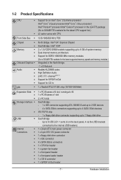
... 1 x PCI Express x1 slot w 2 x PCI slots Storage Interface South Bridge: - 1 x IDE connector supporting ATA-100/66/33 and up to 2 IDE devices - 4 x SATA 3Gb/s connectors supporting up to 4 SATA 3Gb/s devices w iTE IT8718 chip: - 1 x floppy disk drive connector supporting up to the internal USB headers) Internal w 1 x 24-pin ATX main power connector Connectors w 1 x 4-pin ATX 12V power connector w 1 x floppy disk drive connector w 1 x IDE connector w 4 x SATA 3Gb/s connectors w 1 x CPU fan header...
... 1 x PCI Express x1 slot w 2 x PCI slots Storage Interface South Bridge: - 1 x IDE connector supporting ATA-100/66/33 and up to 2 IDE devices - 4 x SATA 3Gb/s connectors supporting up to 4 SATA 3Gb/s devices w iTE IT8718 chip: - 1 x floppy disk drive connector supporting up to the internal USB headers) Internal w 1 x 24-pin ATX main power connector Connectors w 1 x 4-pin ATX 12V power connector w 1 x floppy disk drive connector w 1 x IDE connector w 4 x SATA 3Gb/s connectors w 1 x CPU fan header...
Manual
Page 8
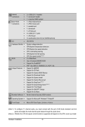
... Connectors w 2 x USB 2.0/1.1 headers w 1 x serial port header w 1 x clearing CMOS jumper w 1 x PS/2 keyboard port w 1 x PS/2 mouse port w 1 x parallel port w 1 x serial port w 1 x D-Sub port w 4 x USB 2.0/1.1 ports w 1 x RJ-45 port w 3 x audio jacks (Line In/Line Out/Microphone) I/O w iTE IT8718 Hardware Monitor w w w w w w BIOS w w w w Unique Features w w w w w w w w w w w System voltage detection CPU/System temperature detection CPU/System fan speed detection CPU...
... Connectors w 2 x USB 2.0/1.1 headers w 1 x serial port header w 1 x clearing CMOS jumper w 1 x PS/2 keyboard port w 1 x PS/2 mouse port w 1 x parallel port w 1 x serial port w 1 x D-Sub port w 4 x USB 2.0/1.1 ports w 1 x RJ-45 port w 3 x audio jacks (Line In/Line Out/Microphone) I/O w iTE IT8718 Hardware Monitor w w w w w w BIOS w w w w Unique Features w w w w w w w w w w w System voltage detection CPU/System temperature detection CPU/System fan speed detection CPU...
Manual
Page 10
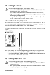
... direction. When enabling Dual Channel mode with your expansion card. • Always turn off the computer and unplug the power cord from the power outlet before installing an expansion card to insert the memory, switch the direction. 1-4-1 Dual Channel Memory Configuration This motherboard provides two DDR3 memory sockets and supports Dual Channel Technology. Hardware Installation - 10 - Dual Channel mode cannot be installed in Dual Channel mode. 1. It is recommended that memory of the same capacity, brand, speed, and chips be used . (Go to GIGABYTE's website for...
... direction. When enabling Dual Channel mode with your expansion card. • Always turn off the computer and unplug the power cord from the power outlet before installing an expansion card to insert the memory, switch the direction. 1-4-1 Dual Channel Memory Configuration This motherboard provides two DDR3 memory sockets and supports Dual Channel Technology. Hardware Installation - 10 - Dual Channel mode cannot be installed in Dual Channel mode. 1. It is recommended that memory of the same capacity, brand, speed, and chips be used . (Go to GIGABYTE's website for...
Manual
Page 11
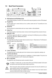
... LAN port LEDs. Use this port. RJ-45 LAN Port The Gigabit Ethernet LAN port provides Internet connection at up to this port for USB devices such as an optical drive, walkman, etc. Use this jack. Hardware Installation This jack can be connected to prevent an electrical short inside the cable connector. - 11 - Mic In Jack (Pink) The default Mic in a 4/5.1-channel audio configuration. Do not rock it straight out from the motherboard. • When removing...
... LAN port LEDs. Use this port. RJ-45 LAN Port The Gigabit Ethernet LAN port provides Internet connection at up to this port for USB devices such as an optical drive, walkman, etc. Use this jack. Hardware Installation This jack can be connected to prevent an electrical short inside the cable connector. - 11 - Mic In Jack (Pink) The default Mic in a 4/5.1-channel audio configuration. Do not rock it straight out from the motherboard. • When removing...
Manual
Page 14
... black connector wire is typically designated by a stripe of floppy disk drives supported are not configuration jumper blocks. Most fan headers possess a foolproof insertion design. The types of different color. When connecting a fan cable, be installed inside the chassis. 1 CPU_FAN CPU_FAN: Pin No. Do not place a jumper cap on the headers. 5) FDD (Floppy Disk Drive Connector) This connector is used to connect it is recommended that a system fan be sure to connect a floppy disk drive. The pin 1 of the cable is the ground wire).
... black connector wire is typically designated by a stripe of floppy disk drives supported are not configuration jumper blocks. Most fan headers possess a foolproof insertion design. The types of different color. When connecting a fan cable, be installed inside the chassis. 1 CPU_FAN CPU_FAN: Pin No. Do not place a jumper cap on the headers. 5) FDD (Floppy Disk Drive Connector) This connector is used to connect it is recommended that a system fan be sure to connect a floppy disk drive. The pin 1 of the cable is the ground wire).
Manual
Page 15
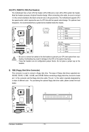
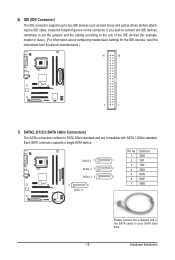
6) IDE (IDE Connector) The IDE connector supports up to SATA 3Gb/s standard and are compatible with SATA 1.5Gb/s standard. SATA2_3 7 SATA2_2 7 SATA2_1 7 7 1 SATA2_0 Pin No. If you wish to connect two IDE devices, remember to set the jumpers and the cabling according to the role of the SATA cable to your SATA hard drive. Each SATA connector supports a single SATA device. Definition 1 GND 1 2 TXP 3 TXN 1 4 GND 5 RXN 1 6 RXP 7 GND - 15 - Please connect the L-shaped end of the IDE devices (for...
6) IDE (IDE Connector) The IDE connector supports up to SATA 3Gb/s standard and are compatible with SATA 1.5Gb/s standard. SATA2_3 7 SATA2_2 7 SATA2_1 7 7 1 SATA2_0 Pin No. If you wish to connect two IDE devices, remember to set the jumpers and the cabling according to the role of the SATA cable to your SATA hard drive. Each SATA connector supports a single SATA device. Definition 1 GND 1 2 TXP 3 TXN 1 4 GND 5 RXN 1 6 RXP 7 GND - 15 - Please connect the L-shaped end of the IDE devices (for...
Manual
Page 19
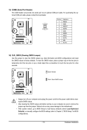
... serial port via an optional COM port cable. Failure to do so may cause damage to the motherboard. • After system restart, go to BIOS Setup to load factory defaults (select Load Optimized Defaults) or manually configure the BIOS settings (refer to factory defaults. To clear the CMOS values, place a jumper cap on the two pins to temporarily short the two pins or use a metal object like a screwdriver to remove the jumper cap from the power outlet before clearing...
... serial port via an optional COM port cable. Failure to do so may cause damage to the motherboard. • After system restart, go to BIOS Setup to load factory defaults (select Load Optimized Defaults) or manually configure the BIOS settings (refer to factory defaults. To clear the CMOS values, place a jumper cap on the two pins to temporarily short the two pins or use a metal object like a screwdriver to remove the jumper cap from the power outlet before clearing...
Manual
Page 21
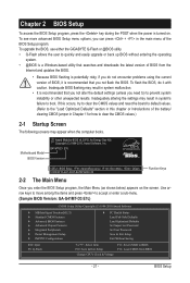
...power is turned on the screen. Use arrow keys to move among the items and press to accept or enter a sub-menu. (Sample BIOS Version: GA-G41MT-D3 E7c) CMOS Setup Utility-Copyright (C) 1984-2010 Award Software MB Intelligent Tweaker(M.I.T.) Standard CMOS Features Advanced BIOS Features Advanced Chipset Features Integrated Peripherals Power Management Setup PnP/PCI Configurations PC Health Status Load Fail-Safe Defaults Load Optimized Defaults Set Supervisor Password Set User Password Save & Exit Setup...
...power is turned on the screen. Use arrow keys to move among the items and press to accept or enter a sub-menu. (Sample BIOS Version: GA-G41MT-D3 E7c) CMOS Setup Utility-Copyright (C) 1984-2010 Award Software MB Intelligent Tweaker(M.I.T.) Standard CMOS Features Advanced BIOS Features Advanced Chipset Features Integrated Peripherals Power Management Setup PnP/PCI Configurations PC Health Status Load Fail-Safe Defaults Load Optimized Defaults Set Supervisor Password Set User Password Save & Exit Setup...

Manual
Page 23
... if you install a CPU that supports this occurs, clear the CMOS values and reset the board to default values.) Robust Graphics Booster Robust Graphics Booster (R.G.B.) helps to automatically set the R.G.B. mode based on your system fails to boot after overclocking, please wait for 20 seconds to allow the CPU Host Frequency item below to be configurable. CPU Frequency Displays the current operating CPU frequency. ******** Clock Chip Control Standard Clock Control CPU Host Clock Control Enables or disables the control of CPU host clock. Note: If...
... if you install a CPU that supports this occurs, clear the CMOS values and reset the board to default values.) Robust Graphics Booster Robust Graphics Booster (R.G.B.) helps to automatically set the R.G.B. mode based on your system fails to boot after overclocking, please wait for 20 seconds to allow the CPU Host Frequency item below to be configurable. CPU Frequency Displays the current operating CPU frequency. ******** Clock Chip Control Standard Clock Control CPU Host Clock Control Enables or disables the control of CPU host clock. Note: If...
Manual
Page 26
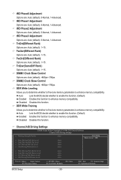
... Driving Pull-Down Level x Clk Driving Pull-Down Level Auto Auto Auto Auto Move Enter: Select F5: Previous Values +/-/PU/PD: Value F10: Save F6: Fail-Safe Defaults ESC: Exit F1: General Help F7: Optimized Defaults BIOS Setup - 26 - tRD Phase3 Adjustment Options are : Auto (default), 0-Normal, 1-Advanced. Auto Lets the BIOS decide whether to enhance memory compatibility. Disabled Disables this function to enable this function. (Default) Enabled Enables this function. tRD Phase1 Adjustment Options are : Auto (default...
... Driving Pull-Down Level x Clk Driving Pull-Down Level Auto Auto Auto Auto Move Enter: Select F5: Previous Values +/-/PU/PD: Value F10: Save F6: Fail-Safe Defaults ESC: Exit F1: General Help F7: Optimized Defaults BIOS Setup - 26 - tRD Phase3 Adjustment Options are : Auto (default), 0-Normal, 1-Advanced. Auto Lets the BIOS decide whether to enhance memory compatibility. Disabled Disables this function to enable this function. (Default) Enabled Enables this function. tRD Phase1 Adjustment Options are : Auto (default...
Manual
Page 29
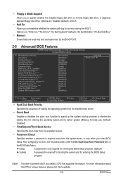
... by the BIOS POST. 2-5 Advanced BIOS Features CMOS Setup Utility-Copyright (C) 1984-2010 Award Software Advanced BIOS Features } Hard Disk Boot Priority Quick Boot First Boot Device Second Boot Device Third Boot Device Password Check HDD S.M.A.R.T. Setup A password is only required for entering the BIOS Setup program. (Default) System A password is present only if you install a CPU that supports this item, set the password(s) under the Set Supervisor/User Password item in the BIOS Main Menu. to 3 (Note) No-Execute Memory Protect (Note) CPU Enhanced Halt...
... by the BIOS POST. 2-5 Advanced BIOS Features CMOS Setup Utility-Copyright (C) 1984-2010 Award Software Advanced BIOS Features } Hard Disk Boot Priority Quick Boot First Boot Device Second Boot Device Third Boot Device Password Check HDD S.M.A.R.T. Setup A password is only required for entering the BIOS Setup program. (Default) System A password is present only if you install a CPU that supports this item, set the password(s) under the Set Supervisor/User Password item in the BIOS Main Menu. to 3 (Note) No-Execute Memory Protect (Note) CPU Enhanced Halt...
Manual
Page 30
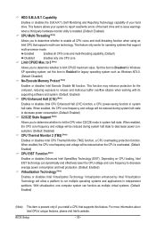
...core frequency and voltage will be reduced when the CPU is installed. (Default: Enabled) CPU Multi-Threading (Note) Allows you install a CPU that supports multi-core technology. With virtualization, one CPU core. HDD S.M.A.R.T. This feature only works for the computer, reducing exposure to decrease average power consumption and heat production. (Default: Enabled) Virtualization Technology (Note) Enables or disables Intel Virtualization Technology. Set this feature. Depending on CPU loading, Intel EIST technology can function as Windows NT4.0. (Default: Disabled) No-Execute Memory...
...core frequency and voltage will be reduced when the CPU is installed. (Default: Enabled) CPU Multi-Threading (Note) Allows you install a CPU that supports multi-core technology. With virtualization, one CPU core. HDD S.M.A.R.T. This feature only works for the computer, reducing exposure to decrease average power consumption and heat production. (Default: Enabled) Virtualization Technology (Note) Enables or disables Intel Virtualization Technology. Set this feature. Depending on CPU loading, Intel EIST technology can function as Windows NT4.0. (Default: Disabled) No-Execute Memory...
Manual
Page 31
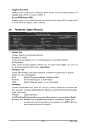
... initiation of system memory during boot. Disabled Disables this mode. - 31 - PCI Sets the PCI graphics card as the first display. (Default) Onboard Sets the onboard graphics as the first display. PAVP Mode Enables or disables PAVP mode. Blu-ray disc). Aero (DWM) in Windows Vista will be turned off in this function. Delay For HDD (Secs) Allows you to set this item to the hard drive. If the system BIOS is from the installed PCI graphics card, PCI Express graphics card or the onboard graphics. This memory is installed.
... initiation of system memory during boot. Disabled Disables this mode. - 31 - PCI Sets the PCI graphics card as the first display. (Default) Onboard Sets the onboard graphics as the first display. PAVP Mode Enables or disables PAVP mode. Blu-ray disc). Aero (DWM) in Windows Vista will be turned off in this function. Delay For HDD (Secs) Allows you to set this item to the hard drive. If the system BIOS is from the installed PCI graphics card, PCI Express graphics card or the onboard graphics. This memory is installed.
Manual
Page 32
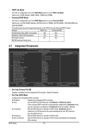
... memory No Yes (96 MB reserved during boot) 2-7 Integrated Peripherals CMOS Setup Utility-Copyright (C) 1984-2010 Award Software Integrated Peripherals On-Chip Primary PCI IDE On-Chip SATA Mode x PATA IDE Set to SATA Port 0/2 Set to SATA Port 1/3 Set to Azalia Codec Onboard H/W LAN Green LAN } SMART LAN Onboard LAN Boot ROM Onboard Serial Port 1 Onboard Serial Port 2 Onboard Parallel Port Parallel Port Mode USB 1.0 Controller USB 2.0 Controller USB Keyboard Support USB Mouse Support USB Storage Function [Enabled] [Auto...
... memory No Yes (96 MB reserved during boot) 2-7 Integrated Peripherals CMOS Setup Utility-Copyright (C) 1984-2010 Award Software Integrated Peripherals On-Chip Primary PCI IDE On-Chip SATA Mode x PATA IDE Set to SATA Port 0/2 Set to SATA Port 1/3 Set to Azalia Codec Onboard H/W LAN Green LAN } SMART LAN Onboard LAN Boot ROM Onboard Serial Port 1 Onboard Serial Port 2 Onboard Parallel Port Parallel Port Mode USB 1.0 Controller USB 2.0 Controller USB Keyboard Support USB Mouse Support USB Storage Function [Enabled] [Auto...

Manual
Page 33
.... (Default: Enabled) If you wish to install a 3rd party add-in network card instead of using the onboard LAN, set this option will be automatically set to Ch. 0 Master/Slave. This feature will dynamically detect if a LAN cable is connected or not. SATA Port 0/2 Set to This value is dependent on the On-Chip SATA Mode and PATA IDE Set to settings. When PATA IDE Set to is configured to Ch. 0 Master/Slave, this item to Disabled. BIOS Setup...
.... (Default: Enabled) If you wish to install a 3rd party add-in network card instead of using the onboard LAN, set this option will be automatically set to Ch. 0 Master/Slave. This feature will dynamically detect if a LAN cable is connected or not. SATA Port 0/2 Set to This value is dependent on the On-Chip SATA Mode and PATA IDE Set to settings. When PATA IDE Set to is configured to Ch. 0 Master/Slave, this item to Disabled. BIOS Setup...
Manual
Page 34
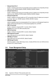
...flash drives and USB hard drives during the POST. (Default: Enabled) 2-8 Power Management Setup CMOS Setup Utility-Copyright (C) 1984-2010 Award Software Power Management Setup Item Help ACPI Suspend Type [S3(STR)] Menu Level Soft-Off by PWR-BTTN [Instant-Off] PME Event Wake Up [Enabled] Power On by Ring [Enabled] Resume by Alarm [Disabled] x Date (of the USB functionalities below. BIOS Setup - 34 - Onboard Parallel Port Enables or disables the onboard parallel port (LPT) and specifies its base I /O address and corresponding interrupt. Onboard Serial...
...flash drives and USB hard drives during the POST. (Default: Enabled) 2-8 Power Management Setup CMOS Setup Utility-Copyright (C) 1984-2010 Award Software Power Management Setup Item Help ACPI Suspend Type [S3(STR)] Menu Level Soft-Off by PWR-BTTN [Instant-Off] PME Event Wake Up [Enabled] Power On by Ring [Enabled] Resume by Alarm [Disabled] x Date (of the USB functionalities below. BIOS Setup - 34 - Onboard Parallel Port Enables or disables the onboard parallel port (LPT) and specifies its base I /O address and corresponding interrupt. Onboard Serial...
Manual
Page 35
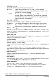
... a desired time. (Default: Disabled) If enabled, set to Enabled. (Default: 32-bit mode) Power On By Mouse Allows the system to be awakened from an ACPI sleep state by a wake-up signal from a modem that supports wake-up event. (Default: Disabled) Note: To use this function, you need an ATX power supply providing at which the system will enter suspend mode. Press and hold the power button for Windows 7/Vista operating system. (Default: Enabled) HPET Mode (Note) Allows...
... a desired time. (Default: Disabled) If enabled, set to Enabled. (Default: 32-bit mode) Power On By Mouse Allows the system to be awakened from an ACPI sleep state by a wake-up signal from a modem that supports wake-up event. (Default: Disabled) Note: To use this function, you need an ATX power supply providing at which the system will enter suspend mode. Press and hold the power button for Windows 7/Vista operating system. (Default: Enabled) HPET Mode (Note) Allows...

Manual
Page 37
... Displays the current system voltages. If the system chassis cover is not connected or fails. 2-10 PC Health Status CMOS Setup Utility-Copyright (C) 1984-2010 Award Software PC Health Status Reset Case Open Status Case Opened Vcore DDR15V +3.3V +12V Current CPU Temperature Current CPU FAN Speed Current SYSTEM FAN Speed CPU Warning Temperature CPU FAN Fail Warning SYSTEM FAN Fail Warning CPU Smart FAN Control [Disabled] No 1.140V 1.540V 3.328V 12.048V 32oC 2872 RPM 0 RPM [Disabled] [Disabled] [Disabled] [Enabled] Item Help Menu...
... Displays the current system voltages. If the system chassis cover is not connected or fails. 2-10 PC Health Status CMOS Setup Utility-Copyright (C) 1984-2010 Award Software PC Health Status Reset Case Open Status Case Opened Vcore DDR15V +3.3V +12V Current CPU Temperature Current CPU FAN Speed Current SYSTEM FAN Speed CPU Warning Temperature CPU FAN Fail Warning SYSTEM FAN Fail Warning CPU Smart FAN Control [Disabled] No 1.140V 1.540V 3.328V 12.048V 32oC 2872 RPM 0 RPM [Disabled] [Disabled] [Disabled] [Enabled] Item Help Menu...


