Manual
Page 1
GA-G41MT-D3 GA-G41MT-ES2L LGA775 socket motherboard for Intel® Core™ processor family/ Intel® Pentium® processor family/Intel® Celeron® processor family User's Manual Rev. 1303 12ME-G41MTD3-1303R
GA-G41MT-D3 GA-G41MT-ES2L LGA775 socket motherboard for Intel® Core™ processor family/ Intel® Pentium® processor family/Intel® Celeron® processor family User's Manual Rev. 1303 12ME-G41MTD3-1303R
Manual
Page 2
Motherboard GA-G41MT-D3/GA-G41MT-ES2L May 12, 2010 Motherboard GA-G41MT-D3/GA-G41MT-ES2L May 12, 2010
Motherboard GA-G41MT-D3/GA-G41MT-ES2L May 12, 2010 Motherboard GA-G41MT-D3/GA-G41MT-ES2L May 12, 2010
Manual
Page 3
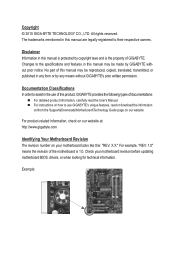
... Information in any means without prior notice. Copyright © 2010 GIGA-BYTE TECHNOLOGY CO., LTD. For example, "REV: 1.0" means the revision of the motherboard is the property of GIGABYTE. Documentation Classifications In order to assist in this manual may be reproduced, copied, translated, transmitted, or published in this : "REV: X.X." The trademarks mentioned...
... Information in any means without prior notice. Copyright © 2010 GIGA-BYTE TECHNOLOGY CO., LTD. For example, "REV: 1.0" means the revision of the motherboard is the property of GIGABYTE. Documentation Classifications In order to assist in this manual may be reproduced, copied, translated, transmitted, or published in this : "REV: X.X." The trademarks mentioned...
Manual
Page 4
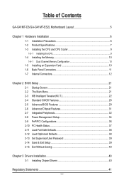
Table of Contents GA-G41MT-D3/GA-G41MT-ES2L Motherboard Layout 5 Chapter 1 Hardware Installation 6 1-1 Installation Precautions 6 1-2 Product Specifications 7 1-3 Installing the CPU and CPU Cooler 9 1-3-1 Installing the CPU...9 1-4 Installing the Memory 10 1-4-1 Dual Channel Memory Configuration ...
Table of Contents GA-G41MT-D3/GA-G41MT-ES2L Motherboard Layout 5 Chapter 1 Hardware Installation 6 1-1 Installation Precautions 6 1-2 Product Specifications 7 1-3 Installing the CPU and CPU Cooler 9 1-3-1 Installing the CPU...9 1-4 Installing the Memory 10 1-4-1 Dual Channel Memory Configuration ...
Manual
Page 5
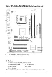
... cable The box contents above are for reference only and the actual items shall depend on the product package you obtain. - 5 - GA-G41MT-D3/GA-G41MT-ES2L Motherboard Layout KB_MS COMA ATX_12V LGA775 CPU_FAN CLR_CMOS GA-G41MT-D3/GA-G41MT-ES2L DDR3_1 DDR3_2 F_PANEL LPT COMB VGA R_USB USB_LAN AUDIO F_AUDIO Realtek RTL8111D/E PCIEX1 PCIEX16 iTE IT8718 PCI1 Intel® G41...
... cable The box contents above are for reference only and the actual items shall depend on the product package you obtain. - 5 - GA-G41MT-D3/GA-G41MT-ES2L Motherboard Layout KB_MS COMA ATX_12V LGA775 CPU_FAN CLR_CMOS GA-G41MT-D3/GA-G41MT-ES2L DDR3_1 DDR3_2 F_PANEL LPT COMB VGA R_USB USB_LAN AUDIO F_AUDIO Realtek RTL8111D/E PCIEX1 PCIEX16 iTE IT8718 PCI1 Intel® G41...
Manual
Page 6
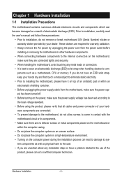
...have an ESD wrist strap, keep your hands dry and first touch a metal object to eliminate static electricity. • Prior to installing the motherboard, please have a problem related to the use of the product, please consult a certified computer technician. These stickers are required for warranty validation.... installation process can become damaged as a result of your dealer. If you are connected tightly and securely. • When handling the motherboard, avoid touching any installation steps or have it on top of an antistatic pad or within the computer casing. • Do not ...
...have an ESD wrist strap, keep your hands dry and first touch a metal object to eliminate static electricity. • Prior to installing the motherboard, please have a problem related to the use of the product, please consult a certified computer technician. These stickers are required for warranty validation.... installation process can become damaged as a result of your dealer. If you are connected tightly and securely. • When handling the motherboard, avoid touching any installation steps or have it on top of an antistatic pad or within the computer casing. • Do not ...
Manual
Page 9
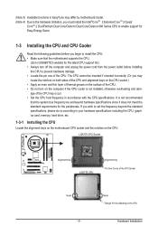
... an even and thin layer of thermal grease on the surface of the CPU Socket Notch - 9 - It is not recommended that the motherboard supports the CPU. (Go to GIGABYTE's website for Easy Energy Saver. 1-3 Installing the CPU and CPU Cooler Read the following guidelines before installing the CPU to your hardware specifications...
... an even and thin layer of thermal grease on the surface of the CPU Socket Notch - 9 - It is not recommended that the motherboard supports the CPU. (Go to GIGABYTE's website for Easy Energy Saver. 1-3 Installing the CPU and CPU Cooler Read the following guidelines before installing the CPU to your hardware specifications...
Manual
Page 10
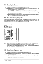
... 1-4 Installing the Memory Read the following guidelines before you begin to insert the memory, switch the direction. 1-4-1 Dual Channel Memory Configuration This motherboard provides two DDR3 memory sockets and supports Dual Channel Technology. A memory module can be used . 1-5 Installing an Expansion Card Read the following... mode with two memory modules, it is recommended that memory of the memory. Dual Channel mode cannot be used . (Go to GIGABYTE's website for the latest supported memory speeds and memory modules.) • Always turn off the computer and unplug the power cord from...
... 1-4 Installing the Memory Read the following guidelines before you begin to insert the memory, switch the direction. 1-4-1 Dual Channel Memory Configuration This motherboard provides two DDR3 memory sockets and supports Dual Channel Technology. A memory module can be used . 1-5 Installing an Expansion Card Read the following... mode with two memory modules, it is recommended that memory of the memory. Dual Channel mode cannot be used . (Go to GIGABYTE's website for the latest supported memory speeds and memory modules.) • Always turn off the computer and unplug the power cord from...
Manual
Page 11
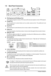
... port. Do not rock it side to side to a back panel connector, first remove the cable from your device and then remove it from the motherboard. • When removing the cable, pull it straight out from the connector. Hardware Installation 1-6 Back Panel Connectors PS/2 Keyboard and PS/2 Mouse Port Use the...
... port. Do not rock it side to side to a back panel connector, first remove the cable from your device and then remove it from the motherboard. • When removing the cable, pull it straight out from the connector. Hardware Installation 1-6 Back Panel Connectors PS/2 Keyboard and PS/2 Mouse Port Use the...
Manual
Page 12
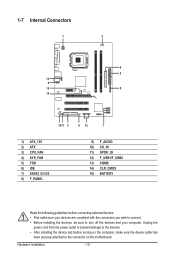
... devices and your devices are compliant with the connectors you wish to connect. • Before installing the devices, be sure to the connector on the motherboard. 1-7 Internal Connectors 1 3 6 2 13 9 15 8 14 1011 5 4 12 7 1) ATX_12V 2) ATX 3) CPU_FAN 4) SYS_FAN 5) FDD 6) IDE 7) SATA2_0/1/2/3 8) F_PANEL 9) 10) 11) 12) 13) 14) 15) F_AUDIO CD_IN SPDIF_IO F_USB1...
... devices and your devices are compliant with the connectors you wish to connect. • Before installing the devices, be sure to the connector on the motherboard. 1-7 Internal Connectors 1 3 6 2 13 9 15 8 14 1011 5 4 12 7 1) ATX_12V 2) ATX 3) CPU_FAN 4) SYS_FAN 5) FDD 6) IDE 7) SATA2_0/1/2/3 8) F_PANEL 9) 10) 11) 12) 13) 14) 15) F_AUDIO CD_IN SPDIF_IO F_USB1...
Manual
Page 13
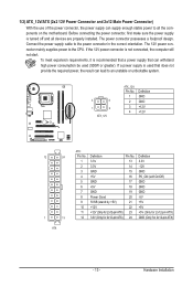
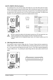
... power connector mainly supplies power to the power connector in the correct orientation. If a power supply is turned off and all the components on the motherboard. If the 12V power connector is recommended that a power supply that does not provide the required power, the result can lead to an unstable or...
... power connector mainly supplies power to the power connector in the correct orientation. If a power supply is turned off and all the components on the motherboard. If the 12V power connector is recommended that a power supply that does not provide the required power, the result can lead to an unstable or...
Manual
Page 14
The motherboard supports CPU fan speed control, which requires the use of different color. Definition 1 GND 2 +12V 3 Sense 4 Speed Control 1 SYS_FAN SYS_FAN: Pin No. 1 2 3 Definition GND +12V ...) This connector is the ground wire). Before connecting a floppy disk drive, be installed inside the chassis. 1 CPU_FAN CPU_FAN: Pin No. 3/4) CPU_FAN/SYS_FAN (Fan Headers) The motherboard has a 4-pin CPU fan header (CPU_FAN) and a 3-pin (SYS_FAN) system fan header. Most fan headers possess a foolproof insertion design. For optimum heat dissipation, it in...
The motherboard supports CPU fan speed control, which requires the use of different color. Definition 1 GND 2 +12V 3 Sense 4 Speed Control 1 SYS_FAN SYS_FAN: Pin No. 1 2 3 Definition GND +12V ...) This connector is the ground wire). Before connecting a floppy disk drive, be installed inside the chassis. 1 CPU_FAN CPU_FAN: Pin No. 3/4) CPU_FAN/SYS_FAN (Fan Headers) The motherboard has a 4-pin CPU fan header (CPU_FAN) and a 3-pin (SYS_FAN) system fan header. Most fan headers possess a foolproof insertion design. For optimum heat dissipation, it in...
Manual
Page 17
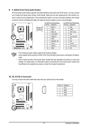
... of the module connector match the pin assignments of the front and back panel audio connections simultane- Incorrect connection between the module connector and the motherboard header will be present on each wire instead of a single plug. Definition 1 CD-L 2 GND 3 GND 4 CD-R - 17 - Definition 2 10 1 MIC2_L Pin...Audio: For AC'97 Front Panel Audio: Pin No. You may connect the audio cable that has separated connectors on both of the motherboard header. ously. • Some chassis provide a front panel audio module that came with your chassis front panel audio module to work...
... of the module connector match the pin assignments of the front and back panel audio connections simultane- Incorrect connection between the module connector and the motherboard header will be present on each wire instead of a single plug. Definition 1 CD-L 2 GND 3 GND 4 CD-R - 17 - Definition 2 10 1 MIC2_L Pin...Audio: For AC'97 Front Panel Audio: Pin No. You may connect the audio cable that has separated connectors on both of the motherboard header. ously. • Some chassis provide a front panel audio module that came with your chassis front panel audio module to work...
Manual
Page 19
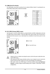
... temporarily short the two pins or use a metal object like a screwdriver to factory defaults. Hardware Installation Failure to do so may cause damage to the motherboard. • After system restart, go to BIOS Setup to load factory defaults (select Load Optimized Defaults) or manually configure the BIOS settings (refer to Chapter...
... temporarily short the two pins or use a metal object like a screwdriver to factory defaults. Hardware Installation Failure to do so may cause damage to the motherboard. • After system restart, go to BIOS Setup to load factory defaults (select Load Optimized Defaults) or manually configure the BIOS settings (refer to Chapter...
Manual
Page 21
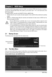
... when the computer boots. Motherboard Model BIOS Version Award Modular BIOS v6.00PG, An Energy Star Ally Copyright (C) 1984-2010, Award Software, Inc. Use arrow keys to move among the items and press to accept or enter a sub-menu. (Sample BIOS Version: GA-G41MT-D3 E7c) CMOS Setup Utility-...values.) 2-1 Startup Screen The following screens may result in the main menu of the BIOS Setup program. To upgrade the BIOS, use either the GIGABYTE Q-Flash or @BIOS utility. • Q-Flash allows the user to quickly and easily upgrade or back up BIOS without entering the operating system...
... when the computer boots. Motherboard Model BIOS Version Award Modular BIOS v6.00PG, An Energy Star Ally Copyright (C) 1984-2010, Award Software, Inc. Use arrow keys to move among the items and press to accept or enter a sub-menu. (Sample BIOS Version: GA-G41MT-D3 E7c) CMOS Setup Utility-...values.) 2-1 Startup Screen The following screens may result in the main menu of the BIOS Setup program. To upgrade the BIOS, use either the GIGABYTE Q-Flash or @BIOS utility. • Q-Flash allows the user to quickly and easily upgrade or back up BIOS without entering the operating system...

Manual
Page 33
...; Move Enter: Select F5: Previous Values +/-/PU/PD: Value F10: Save F6: Fail-Safe Defaults ESC: Exit F1: General Help F7: Optimized Defaults This motherboard incorporates cable diagnostic feature designed to detect the status of using the onboard audio, set to Ch. 0 Master/Slave. PATA IDE Set to This item...
...; Move Enter: Select F5: Previous Values +/-/PU/PD: Value F10: Save F6: Fail-Safe Defaults ESC: Exit F1: General Help F7: Optimized Defaults This motherboard incorporates cable diagnostic feature designed to detect the status of using the onboard audio, set to Ch. 0 Master/Slave. PATA IDE Set to This item...

Manual
Page 37
... connected or fails. Current CPU/SYSTEM FAN Speed (RPM) Displays current CPU/system fan speed. CPU/SYSTEM FAN Fail Warning Allows the system to the motherboard CI header. 2-10 PC Health Status CMOS Setup Utility-Copyright (C) 1984-2010 Award Software PC Health Status Reset Case Open Status Case Opened Vcore DDR15V...
... connected or fails. Current CPU/SYSTEM FAN Speed (RPM) Displays current CPU/system fan speed. CPU/SYSTEM FAN Fail Warning Allows the system to the motherboard CI header. 2-10 PC Health Status CMOS Setup Utility-Copyright (C) 1984-2010 Award Software PC Health Status Reset Case Open Status Case Opened Vcore DDR15V...
Manual
Page 38
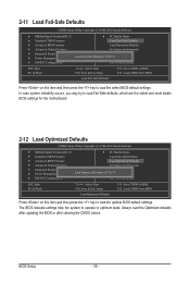
... - 38 - In case system instability occurs, you may try to load Fail-Safe defaults, which are the safest and most stable BIOS settings for the motherboard. 2-12 Load Optimized Defaults CMOS Setup Utility-Copyright (C) 1984-2010 Award Software MB Intelligent Tweaker(M.I .T.) PC Health Status Standard CMOS Features Load...
... - 38 - In case system instability occurs, you may try to load Fail-Safe defaults, which are the safest and most stable BIOS settings for the motherboard. 2-12 Load Optimized Defaults CMOS Setup Utility-Copyright (C) 1984-2010 Award Software MB Intelligent Tweaker(M.I .T.) PC Health Status Standard CMOS Features Load...

Manual
Page 40
... wish to the CMOS. Chapter 3 Drivers Installation • Before installing the drivers, first install the operating system. • After installing the operating system, insert the motherboard driver disk into your system and then list all the drivers that shown in BIOS Setup to install. Press or to return to BIOS F12...
... wish to the CMOS. Chapter 3 Drivers Installation • Before installing the drivers, first install the operating system. • After installing the operating system, insert the motherboard driver disk into your system and then list all the drivers that shown in BIOS Setup to install. Press or to return to BIOS F12...
Manual
Page 41
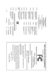
... contained herein was accurate in your product's user's manual and we at the Customer Care number listed in all GIGABYTE motherboards fulfill European Union regulations for RoHS (Restriction of environmentally safe recycling. To prevent releases of harmful substances into the environment... This document must not be copied without notice and should be prosecuted. Waste Electrical & Electronic Equipment (WEEE) Directive Statement GIGABYTE will be used equipment must be marked, collected separately, and disposed of electric and electronic devices and their components. Under ...
... contained herein was accurate in your product's user's manual and we at the Customer Care number listed in all GIGABYTE motherboards fulfill European Union regulations for RoHS (Restriction of environmentally safe recycling. To prevent releases of harmful substances into the environment... This document must not be copied without notice and should be prosecuted. Waste Electrical & Electronic Equipment (WEEE) Directive Statement GIGABYTE will be used equipment must be marked, collected separately, and disposed of electric and electronic devices and their components. Under ...


