Manual
Page 3
...REV: 1.0" means the revision of the motherboard is the property of GIGABYTE. Example: All rights reserved. Check your motherboard looks like this manual...information, check on our website at: http://www.gigabyte.com.tw Identifying Your Motherboard Revision The revision number on ...their respective owners. The trademarks mentioned in any form or by GIGABYTE without GIGABYTE's prior written permission. Documentation Classifications In order to assist in ... our website. No part of this product, GIGABYTE provides the following types of this manual may be reproduced, copied,...
...REV: 1.0" means the revision of the motherboard is the property of GIGABYTE. Example: All rights reserved. Check your motherboard looks like this manual...information, check on our website at: http://www.gigabyte.com.tw Identifying Your Motherboard Revision The revision number on ...their respective owners. The trademarks mentioned in any form or by GIGABYTE without GIGABYTE's prior written permission. Documentation Classifications In order to assist in ... our website. No part of this product, GIGABYTE provides the following types of this manual may be reproduced, copied,...
Manual
Page 4
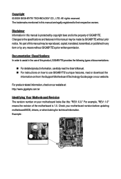
Table of Contents Box Contents ...6 OptionalItems...6 GA-G41M-ES2L Motherboard Layout 7 Block Diagram...8 Chapter 1 Hardware Installation 9 1-1 Installation Precautions 9 1-2 Product Specifications 10 1-3 Installing the CPU and CPU ... Installing an Expansion Card 18 1-6 Back Panel Connectors 19 1-7 Internal Connectors 21 Chapter 2 BIOS Setup 31 2-1 Startup Screen 32 2-2 The Main Menu 33 2-3 MB Intelligent Tweaker(M.I.T 35 2-4 Standard CMOS Features 41 2-5 Advanced BIOS Features 43 2-6 Advanced Chipset Features 45 2-7 IntegratedPeripherals 47 2-8 Power Management Setup 50 2-9...
Table of Contents Box Contents ...6 OptionalItems...6 GA-G41M-ES2L Motherboard Layout 7 Block Diagram...8 Chapter 1 Hardware Installation 9 1-1 Installation Precautions 9 1-2 Product Specifications 10 1-3 Installing the CPU and CPU ... Installing an Expansion Card 18 1-6 Back Panel Connectors 19 1-7 Internal Connectors 21 Chapter 2 BIOS Setup 31 2-1 Startup Screen 32 2-2 The Main Menu 33 2-3 MB Intelligent Tweaker(M.I.T 35 2-4 Standard CMOS Features 41 2-5 Advanced BIOS Features 43 2-6 Advanced Chipset Features 45 2-7 IntegratedPeripherals 47 2-8 Power Management Setup 50 2-9...
Manual
Page 5
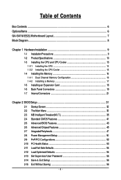
... 58 3-3 Technical Manuals 58 3-4 Contact ...59 3-5 System ...59 3-6 Download Center 60 Chapter 4 Unique Features 61 4-1 Xpress Recovery2 61 4-2 BIOS Update Utilities 64 4-2-1 Updating the BIOS with the Q-Flash Utility 64 4-2-2 Updating the BIOS with the @BIOS Utility 67 4-3 EasyTune 6 ...68 4-4 Easy Energy Saver 69 4-5 Q-Share ...71 4-6 Time Repair ...72 Chapter 5 Appendix ...73 5-1 Configuring Audio...
... 58 3-3 Technical Manuals 58 3-4 Contact ...59 3-5 System ...59 3-6 Download Center 60 Chapter 4 Unique Features 61 4-1 Xpress Recovery2 61 4-2 BIOS Update Utilities 64 4-2-1 Updating the BIOS with the Q-Flash Utility 64 4-2-2 Updating the BIOS with the @BIOS Utility 67 4-3 EasyTune 6 ...68 4-4 Easy Energy Saver 69 4-5 Q-Share ...71 4-6 Time Repair ...72 Chapter 5 Appendix ...73 5-1 Configuring Audio...
Manual
Page 8
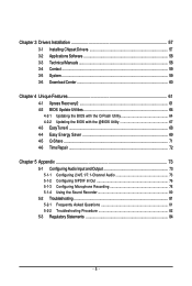
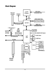
Block Diagram PCIe CLK (100 MHz) D-Sub PCI Express x16 1 PCI Express x1 LAN PCIe CLK RJ45 (100 MHz) x1 RTL8111C/D(L) PCI Express Bus PCI Bus LGA775 Processor Host Interface Intel® G41 CPU CLK+/(333/266/200 MHz) DDR2 800/667 MHz Dual Channel Memory GMCH CLK (333/266/200 MHz) Intel® ICH7 CODEC Dual BIOS ATA-100/66/33 IDE Channel 4 SATA 3Gb/s 8 USB Ports IT8718 Floppy LPT Port COM Ports PS/2 KB/Mouse 2 PCI PCI CLK (33 MHz) Surround Speaker Out Center/Subwoofer Speaker Out Side Speaker Out MIC Line Out Line In S/PDIF In S/PDIF Out - 8 -
Block Diagram PCIe CLK (100 MHz) D-Sub PCI Express x16 1 PCI Express x1 LAN PCIe CLK RJ45 (100 MHz) x1 RTL8111C/D(L) PCI Express Bus PCI Bus LGA775 Processor Host Interface Intel® G41 CPU CLK+/(333/266/200 MHz) DDR2 800/667 MHz Dual Channel Memory GMCH CLK (333/266/200 MHz) Intel® ICH7 CODEC Dual BIOS ATA-100/66/33 IDE Channel 4 SATA 3Gb/s 8 USB Ports IT8718 Floppy LPT Port COM Ports PS/2 KB/Mouse 2 PCI PCI CLK (33 MHz) Surround Speaker Out Center/Subwoofer Speaker Out Side Speaker Out MIC Line Out Line In S/PDIF In S/PDIF Out - 8 -
Manual
Page 11
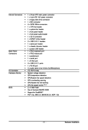
...; CPU temperature detection CPU/System fan speed detection CPU overheating warning CPU/System fan fail warning CPU fan speed control (Note 3) BIOS 2 x 8 Mbit flash Use of licensed AWARD BIOS Support for DualBIOSTM PnP 1.0a, DMI 2.0, SM...
...; CPU temperature detection CPU/System fan speed detection CPU overheating warning CPU/System fan fail warning CPU fan speed control (Note 3) BIOS 2 x 8 Mbit flash Use of licensed AWARD BIOS Support for DualBIOSTM PnP 1.0a, DMI 2.0, SM...
Manual
Page 12
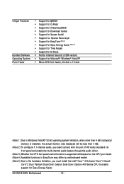
Unique Features Bundled Software Operating System Form Factor Support for @BIOS Support for Q-Flash Support for Virtual DualBIOS Support for Download Center Support for Xpress Install Support for Xpress Recovery2 ... Intel® CoreTM 2 Extreme/ CoreTM 2 Quad/ CoreTM 2 Duo/ Pentium Dual-Core/ Celeron Dual-Core/ Celeron 400 Series CPU to enable support for Easy Energy Saver. GA-G41M-ES2L Motherboard - 12 -
Unique Features Bundled Software Operating System Form Factor Support for @BIOS Support for Q-Flash Support for Virtual DualBIOS Support for Download Center Support for Xpress Install Support for Xpress Recovery2 ... Intel® CoreTM 2 Extreme/ CoreTM 2 Quad/ CoreTM 2 Duo/ Pentium Dual-Core/ Celeron Dual-Core/ Celeron 400 Series CPU to enable support for Easy Energy Saver. GA-G41M-ES2L Motherboard - 12 -

Manual
Page 16
...DDR2_2 Due to install the memory: • Make sure that the motherboard supports the memory. GA-G41M-ES2L Motherboard - 16 - Enabling Dual Channel memory mode will automatically detect the specifications and capacity of... installed in Dual Channel mode. 1. Dual Channel mode cannot be used . (Go to GIGABYTE's website for the latest memory support list.) • Always turn off the computer and ...outlet before installing the memory in only one DDR2 memory module is installed, the BIOS will double the original memory bandwidth. If you begin to chipset limitation, read...
...DDR2_2 Due to install the memory: • Make sure that the motherboard supports the memory. GA-G41M-ES2L Motherboard - 16 - Enabling Dual Channel memory mode will automatically detect the specifications and capacity of... installed in Dual Channel mode. 1. Dual Channel mode cannot be used . (Go to GIGABYTE's website for the latest memory support list.) • Always turn off the computer and ...outlet before installing the memory in only one DDR2 memory module is installed, the BIOS will double the original memory bandwidth. If you begin to chipset limitation, read...
Manual
Page 18
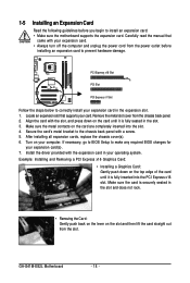
...lift the card straight out from the chassis back panel. 2. Locate an expansion slot that came with your computer. If necessary, go to BIOS Setup to prevent hardware damage. Example: Installing and Removing a PCI Express x16 Graphics Card: • Installing a Graphics Card: Gently push down... card: • Make sure the motherboard supports the expansion card. After installing all expansion cards, replace the chassis cover(s). 6. GA-G41M-ES2L Motherboard - 18 - 1-5 Installing an Expansion Card Read the following guidelines before installing an expansion card to make any required...
...lift the card straight out from the chassis back panel. 2. Locate an expansion slot that came with your computer. If necessary, go to BIOS Setup to prevent hardware damage. Example: Installing and Removing a PCI Express x16 Graphics Card: • Installing a Graphics Card: Gently push down... card: • Make sure the motherboard supports the expansion card. After installing all expansion cards, replace the chassis cover(s). 6. GA-G41M-ES2L Motherboard - 18 - 1-5 Installing an Expansion Card Read the following guidelines before installing an expansion card to make any required...
Manual
Page 25
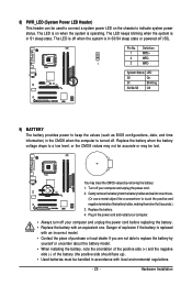
... system is operating. System Status LED S0 On S1 Blinking S3/S4/S5 Off 9) BATTERY The battery provides power to keep the values (such as BIOS configurations, date, and time information) in accordance with an incorrect model. • Contact the place of explosion if the battery is on the chassis to...
... system is operating. System Status LED S0 On S1 Blinking S3/S4/S5 Off 9) BATTERY The battery provides power to keep the values (such as BIOS configurations, date, and time information) in accordance with an incorrect model. • Contact the place of explosion if the battery is on the chassis to...
Manual
Page 26
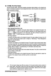
... correctly. One single short beep will be heard if no problem is detected, the BIOS may differ by issuing a beep code. When connecting your system using the power switch (refer to Chapter 2, "BIOS Setup," "Power Management Setup," for information about beep codes. • HD (IDE...chassis front panel. A front panel module mainly consists of power switch, reset switch, power LED, hard drive activity LED, speaker and etc. GA-G41M-ES2L Motherboard - 26 - If a problem is detected at system startup. Note the positive and negative pins before connecting the cables. HDHD+ Reset Switch...
... correctly. One single short beep will be heard if no problem is detected, the BIOS may differ by issuing a beep code. When connecting your system using the power switch (refer to Chapter 2, "BIOS Setup," "Power Management Setup," for information about beep codes. • HD (IDE...chassis front panel. A front panel module mainly consists of power switch, reset switch, power LED, hard drive activity LED, speaker and etc. GA-G41M-ES2L Motherboard - 26 - If a problem is detected at system startup. Note the positive and negative pins before connecting the cables. HDHD+ Reset Switch...
Manual
Page 29
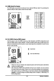
... so may cause damage to the motherboard. • After system restart, go to BIOS Setup to load factory defaults (select Load Optimized Defaults) or manually configure the BIOS settings (refer to Chapter 2, "BIOS Setup," for a few seconds. date information and BIOS configurations) and reset the CMOS values to clear the CMOS values (e.g. For purchasing... the jumper cap from the jumper. To clear the CMOS values, place a jumper cap on your computer, be sure to touch the two pins for BIOS configurations). - 29 -
... so may cause damage to the motherboard. • After system restart, go to BIOS Setup to load factory defaults (select Load Optimized Defaults) or manually configure the BIOS settings (refer to Chapter 2, "BIOS Setup," for a few seconds. date information and BIOS configurations) and reset the CMOS values to clear the CMOS values (e.g. For purchasing... the jumper cap from the jumper. To clear the CMOS values, place a jumper cap on your computer, be sure to touch the two pins for BIOS configurations). - 29 -
Manual
Page 31
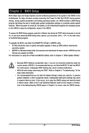
... need to) to prevent system instability or other unexpected results. To upgrade the BIOS, use either the GIGABYTE Q-Flash or @BIOS utility. • Q-Flash allows the user to quickly and easily upgrade or back up BIOS without entering the operating system. • @BIOS is a Windows-based utility that you can press + in the main menu...
... need to) to prevent system instability or other unexpected results. To upgrade the BIOS, use either the GIGABYTE Q-Flash or @BIOS utility. • Q-Flash allows the user to quickly and easily upgrade or back up BIOS without entering the operating system. • @BIOS is a Windows-based utility that you can press + in the main menu...
Manual
Page 32
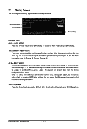
.... : XPRESS RECOVERY2 If you to set the first boot device without having to accept. You can be based on BIOS Setup settings. GA-G41M-ES2L Motherboard - 32 - In Boot Menu, use the up hard drive data using the driver disk, the key can access Boot Menu again to change the ...boot order will directly boot from the device configured in Boot Menu is effective for subsequent access to access the Q-Flash utility directly without entering BIOS Setup. 2-1 Startup Screen The following screens may appear when the computer boots. Note: The setting in Boot Menu. Motherboard Model...
.... : XPRESS RECOVERY2 If you to set the first boot device without having to accept. You can be based on BIOS Setup settings. GA-G41M-ES2L Motherboard - 32 - In Boot Menu, use the up hard drive data using the driver disk, the key can access Boot Menu again to change the ...boot order will directly boot from the device configured in Boot Menu is effective for subsequent access to access the Q-Flash utility directly without entering BIOS Setup. 2-1 Startup Screen The following screens may appear when the computer boots. Note: The setting in Boot Menu. Motherboard Model...
Manual
Page 33
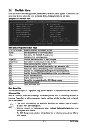
... Defaults Set Supervisor Password Set User Password Save & Exit Setup Exit Without Saving F11: Save CMOS to BIOS F12: Load CMOS from BIOS Change CPU's Clock & Voltage BIOS Setup Program Function Keys Move the selection bar to select an item Execute command or enter the submenu Main...settings for the current submenus Access the Q-Flash utility Display system information Save all the changes and exit the BIOS Setup program Save CMOS to BIOS Load CMOS from BIOS Main Menu Help The onscreen description of a highlighted setup option is displayed on the bottom line of the ...
... Defaults Set Supervisor Password Set User Password Save & Exit Setup Exit Without Saving F11: Save CMOS to BIOS F12: Load CMOS from BIOS Change CPU's Clock & Voltage BIOS Setup Program Function Keys Move the selection bar to select an item Execute command or enter the submenu Main...settings for the current submenus Access the Q-Flash utility Display system information Save all the changes and exit the BIOS Setup program Save CMOS to BIOS Load CMOS from BIOS Main Menu Help The onscreen description of a highlighted setup option is displayed on the bottom line of the ...

Manual
Page 34
First enter the profile name (to erase the default profile name, use this function to the CMOS and exit BIOS Setup. (Pressing can also carry out this task.) GA-G41M-ES2L Motherboard - 34 - It allows you to restrict access to see information about autodetected system/CPU temperature, system voltage and...61550; MB Intelligent Tweaker(M.I.T.) Use this menu to configure the clock, frequency and voltages of your system becomes unstable and you have loaded the BIOS default settings, you can create up to 8 profiles (Profile 1-8) and name each profile. You can use the SPACE key) and then ...
First enter the profile name (to erase the default profile name, use this function to the CMOS and exit BIOS Setup. (Pressing can also carry out this task.) GA-G41M-ES2L Motherboard - 34 - It allows you to restrict access to see information about autodetected system/CPU temperature, system voltage and...61550; MB Intelligent Tweaker(M.I.T.) Use this menu to configure the clock, frequency and voltages of your system becomes unstable and you have loaded the BIOS default settings, you can create up to 8 profiles (Profile 1-8) and name each profile. You can use the SPACE key) and then ...
Manual
Page 35
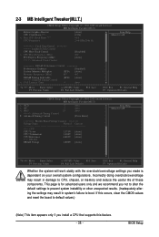
If this feature. - 35 - BIOS Setup Incorrectly doing overclock/overvoltage may result in damage to boot. This page is dependent on your overall system configurations. 2-3 MB Intelligent Tweaker(M.I.T.) CMOS Setup ...
If this feature. - 35 - BIOS Setup Incorrectly doing overclock/overvoltage may result in damage to boot. This page is dependent on your overall system configurations. 2-3 MB Intelligent Tweaker(M.I.T.) CMOS Setup ...
Manual
Page 36
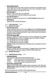
Auto allows the BIOS to 266 MHz. The item is present only if a CPU with the CPU specifications. The adjustable range is installed. For a 1066 MHz FSB CPU, set ... Control CPU Host Clock Control Enables or disables the control of the graphics chip and memory. System Memory Multiplier (SPD) Allows you to 333 MHz. GA-G41M-ES2L Motherboard - 36 - Options are dependent on system configurations. For a 1333 MHz FSB CPU, set the PCIe clock frequency. Extreme Lets the system operate at three...
Auto allows the BIOS to 266 MHz. The item is present only if a CPU with the CPU specifications. The adjustable range is installed. For a 1066 MHz FSB CPU, set ... Control CPU Host Clock Control Enables or disables the control of the graphics chip and memory. System Memory Multiplier (SPD) Allows you to 333 MHz. GA-G41M-ES2L Motherboard - 36 - Options are dependent on system configurations. For a 1333 MHz FSB CPU, set the PCIe clock frequency. Extreme Lets the system operate at three...
Manual
Page 37
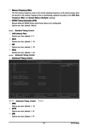
... being used; DRAM Timing Selectable (SPD) Manual allows all DRAM timing control items below to the CPU Host Frequency (Mhz) and System Memory Multiplier settings. BIOS Setup tWTR Options are : Auto (default), 1~15.
... being used; DRAM Timing Selectable (SPD) Manual allows all DRAM timing control items below to the CPU Host Frequency (Mhz) and System Memory Multiplier settings. BIOS Setup tWTR Options are : Auto (default), 1~15.
Manual
Page 39
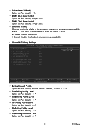
... Driving Pull-Up Level Options are : Auto (default), +8~-7. Data Driving Pull-Down Level Options are : Auto (default), +8~-7. Auto Lets the BIOS decide whether to enable this function. (Default) Disabled Disables this function to enhance memory compatibility. Cmd Driving Pull-Up Level Options are : Auto... (default), +8~-7. - 39 - DIMM2 Clock Skew Control Options are : Auto (default), +8~-7. BIOS Setup DDR Write Training Allows you to determine whether to fine-tune memory parameters to enhance memory compatibility. Enabled Enables this function. ...
... Driving Pull-Up Level Options are : Auto (default), +8~-7. Data Driving Pull-Down Level Options are : Auto (default), +8~-7. Auto Lets the BIOS decide whether to enable this function. (Default) Disabled Disables this function to enhance memory compatibility. Cmd Driving Pull-Up Level Options are : Auto... (default), +8~-7. - 39 - DIMM2 Clock Skew Control Options are : Auto (default), +8~-7. BIOS Setup DDR Write Training Allows you to determine whether to fine-tune memory parameters to enhance memory compatibility. Enabled Enables this function. ...

Manual
Page 41
... 0 Master/Slave Configure your IDE/SATA devices by using one of the three methods below : • Auto • None Access Mode Lets BIOS automatically detect IDE/SATA devices during the POST. (Default) If no IDE/SATA devices are used , set the date. Extended IDE Drive Configure your... IDE/SATA devices by using one of the two methods below : • Auto • None Lets BIOS automatically detect IDE/SATA devices during the POST. (Default) If no IDE/SATA devices are used , set this item to manually enter the specifications...
... 0 Master/Slave Configure your IDE/SATA devices by using one of the three methods below : • Auto • None Access Mode Lets BIOS automatically detect IDE/SATA devices during the POST. (Default) If no IDE/SATA devices are used , set the date. Extended IDE Drive Configure your... IDE/SATA devices by using one of the two methods below : • Auto • None Lets BIOS automatically detect IDE/SATA devices during the POST. (Default) If no IDE/SATA devices are used , set this item to manually enter the specifications...


