Manual
Page 3
...Motherboard\Technology Guide page on your motherboard revision before updating motherboard BIOS, drivers, or when looking for technical information. For product-related information, check on our website at: http://www.gigabyte.com.tw Identifying Your Motherboard Revision The revision number on ...or published in this : "REV: X.X." Check your motherboard looks like this manual may be made by any form or by GIGABYTE without GIGABYTE's prior written permission. Copyright © 2009 GIGA-BYTE TECHNOLOGY CO., LTD. Changes to their respective owners. Disclaimer Information in ...
...Motherboard\Technology Guide page on your motherboard revision before updating motherboard BIOS, drivers, or when looking for technical information. For product-related information, check on our website at: http://www.gigabyte.com.tw Identifying Your Motherboard Revision The revision number on ...or published in this : "REV: X.X." Check your motherboard looks like this manual may be made by any form or by GIGABYTE without GIGABYTE's prior written permission. Copyright © 2009 GIGA-BYTE TECHNOLOGY CO., LTD. Changes to their respective owners. Disclaimer Information in ...
Manual
Page 4
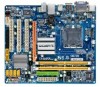
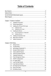
Table of Contents Box Contents...6 Optional Items...6 GA-G41M-ES2H Motherboard Layout 7 Block Diagram...8 Chapter 1 Hardware Installation 9 1-1 Installation Precautions 9 1-2 Product Specifications 10 1-3 Installing the CPU and CPU Cooler... Installing an Expansion Card 18 1-6 Back Panel Connectors 19 1-7 Internal Connectors 21 Chapter 2 BIOS Setup 31 2-1 Startup Screen 32 2-2 The Main Menu 33 2-3 MB Intelligent Tweaker(M.I.T 35 2-4 Standard CMOS Features 41 2-5 Advanced BIOS Features 43 2-6 Advanced Chipset Features 45 2-7 Integrated Peripherals 47 2-8 Power Management Setup 50 ...
Table of Contents Box Contents...6 Optional Items...6 GA-G41M-ES2H Motherboard Layout 7 Block Diagram...8 Chapter 1 Hardware Installation 9 1-1 Installation Precautions 9 1-2 Product Specifications 10 1-3 Installing the CPU and CPU Cooler... Installing an Expansion Card 18 1-6 Back Panel Connectors 19 1-7 Internal Connectors 21 Chapter 2 BIOS Setup 31 2-1 Startup Screen 32 2-2 The Main Menu 33 2-3 MB Intelligent Tweaker(M.I.T 35 2-4 Standard CMOS Features 41 2-5 Advanced BIOS Features 43 2-6 Advanced Chipset Features 45 2-7 Integrated Peripherals 47 2-8 Power Management Setup 50 ...
Manual
Page 5
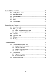
... 58 3-3 Technical Manuals 58 3-4 Contact...59 3-5 System...59 3-6 Download Center 60 Chapter 4 Unique Features 61 4-1 Xpress Recovery2 61 4-2 BIOS Update Utilities 64 4-2-1 Updating the BIOS with the Q-Flash Utility 64 4-2-2 Updating the BIOS with the @BIOS Utility 67 4-3 EasyTune 6...68 4-4 Easy Energy Saver 69 4-5 Q-Share...71 4-6 Time Repair...72 Chapter 5 Appendix...73 5-1 Configuring Audio...
... 58 3-3 Technical Manuals 58 3-4 Contact...59 3-5 System...59 3-6 Download Center 60 Chapter 4 Unique Features 61 4-1 Xpress Recovery2 61 4-2 BIOS Update Utilities 64 4-2-1 Updating the BIOS with the Q-Flash Utility 64 4-2-2 Updating the BIOS with the @BIOS Utility 67 4-3 EasyTune 6...68 4-4 Easy Energy Saver 69 4-5 Q-Share...71 4-6 Time Repair...72 Chapter 5 Appendix...73 5-1 Configuring Audio...
Manual
Page 8
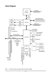
.../266/200 MHz) Host Interface Intel® G41 DDR2 800/667 MHz Dual Channel Memory GMCH CLK (333/266/200 MHz) Intel® ICH7 Dual BIOS ATA-100/66/33 IDE Channel 4 SATA 3Gb/s 8 USB Ports CODEC IT8720 Floppy COM Port PS/2 KB/Mouse Surround Speaker Out Center/Subwoofer Speaker Out...
.../266/200 MHz) Host Interface Intel® G41 DDR2 800/667 MHz Dual Channel Memory GMCH CLK (333/266/200 MHz) Intel® ICH7 Dual BIOS ATA-100/66/33 IDE Channel 4 SATA 3Gb/s 8 USB Ports CODEC IT8720 Floppy COM Port PS/2 KB/Mouse Surround Speaker Out Center/Subwoofer Speaker Out...
Manual
Page 11
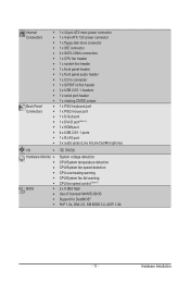
.../2 mouse port w 1 x D-Sub port w 1 x DVI-D port (Note 3) w 1 x HDMI port w 4 x USB 2.0/1.1 ports w 1 x RJ-45 port w 3 x audio jacks (Line In/Line Out/Microphone) I/O w iTE IT8720 Hardware Monitor w w w w w w BIOS w w w w System voltage detection CPU/System temperature detection CPU/System fan speed detection CPU overheating warning CPU/System fan fail warning CPU fan speed control (Note...
.../2 mouse port w 1 x D-Sub port w 1 x DVI-D port (Note 3) w 1 x HDMI port w 4 x USB 2.0/1.1 ports w 1 x RJ-45 port w 3 x audio jacks (Line In/Line Out/Microphone) I/O w iTE IT8720 Hardware Monitor w w w w w w BIOS w w w w System voltage detection CPU/System temperature detection CPU/System fan speed detection CPU overheating warning CPU/System fan fail warning CPU fan speed control (Note...
Manual
Page 12
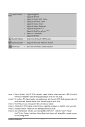
Hardware Installation - 12 - Unique Features w w w w w w w w w w Bundled Software w Support for @BIOS Support for Q-Flash Support for Xpress BIOS Rescue Support for Download Center Support for Xpress Install Support for Xpress Recovery2 Support for EasyTune (Note 5) Support for Easy Energy Saver (Note 6) Support for ...
Hardware Installation - 12 - Unique Features w w w w w w w w w w Bundled Software w Support for @BIOS Support for Q-Flash Support for Xpress BIOS Rescue Support for Download Center Support for Xpress Install Support for Xpress Recovery2 Support for EasyTune (Note 5) Support for Easy Energy Saver (Note 6) Support for ...
Manual
Page 16
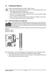
... Channel Memory Configuration This motherboard provides four DDR2 memory sockets and supports Dual Channel Technology. Dual Channel mode cannot be used . (Go to GIGABYTE's website for the latest memory support list.) • Always turn off the computer and unplug the power cord from the power outlet before ...installing the memory in only one DDR2 memory module is installed, the BIOS will double the original memory bandwidth. When enabling Dual Channel mode with two memory modules, it is recommended that memory of the ...
... Channel Memory Configuration This motherboard provides four DDR2 memory sockets and supports Dual Channel Technology. Dual Channel mode cannot be used . (Go to GIGABYTE's website for the latest memory support list.) • Always turn off the computer and unplug the power cord from the power outlet before ...installing the memory in only one DDR2 memory module is installed, the BIOS will double the original memory bandwidth. When enabling Dual Channel mode with two memory modules, it is recommended that memory of the ...
Manual
Page 18
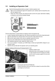
... that came with a screw. 5. 1-5 Installing an Expansion Card Read the following guidelines before installing an expansion card to prevent hardware damage. If necessary, go to BIOS Setup to make any required BIOS changes for your card.
... that came with a screw. 5. 1-5 Installing an Expansion Card Read the following guidelines before installing an expansion card to prevent hardware damage. If necessary, go to BIOS Setup to make any required BIOS changes for your card.
Manual
Page 20
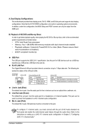
... in operating system environments. Refer to 1 Gbps data rate. In addition, under this audio jack for line in a 4/5.1-channel audio configuration. Use this configuration, the BIOS Setup and POST screens can be used to this jack. Microphones must be output from the HDMI port. The following describes the states of HD...
... in operating system environments. Refer to 1 Gbps data rate. In addition, under this audio jack for line in a 4/5.1-channel audio configuration. Use this configuration, the BIOS Setup and POST screens can be used to this jack. Microphones must be output from the HDMI port. The following describes the states of HD...
Manual
Page 25
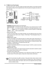
...the reset switch on when the hard drive is detected at system startup. When connecting your system using the power switch (refer to Chapter 2, "BIOS Setup," "Power Management Setup," for information about beep codes. • HD (Hard Drive Activity LED, Blue) Connects to indicate the problem. ...): Connects to the chassis intrusion switch/sensor on the chassis front panel to the power status indicator on when the system is detected, the BIOS may differ by issuing a beep code. 8) F_PANEL (Front Panel Header) Connect the power switch, reset switch, speaker and system status indicator...
...the reset switch on when the hard drive is detected at system startup. When connecting your system using the power switch (refer to Chapter 2, "BIOS Setup," "Power Management Setup," for information about beep codes. • HD (Hard Drive Activity LED, Blue) Connects to indicate the problem. ...): Connects to the chassis intrusion switch/sensor on the chassis front panel to the power status indicator on when the system is detected, the BIOS may differ by issuing a beep code. 8) F_PANEL (Front Panel Header) Connect the power switch, reset switch, speaker and system status indicator...
Manual
Page 28
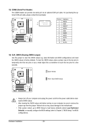
...) and reset the CMOS values to touch the two pins for BIOS configurations). To clear the CMOS values, place a jumper cap on your computer and unplug the power cord from the jumper. Hardware Installation - 28 - Definition 1 NDCD- 9 1 ... dealer. Failure to do so may cause damage to the motherboard. • After system restart, go to BIOS Setup to load factory defaults (select Load Optimized Defaults) or manually configure the BIOS settings (refer to Chapter 2, "BIOS Setup," for a few seconds. Pin No. 13) COMA (Serial Port Header) The COMA header can provide...
...) and reset the CMOS values to touch the two pins for BIOS configurations). To clear the CMOS values, place a jumper cap on your computer and unplug the power cord from the jumper. Hardware Installation - 28 - Definition 1 NDCD- 9 1 ... dealer. Failure to do so may cause damage to the motherboard. • After system restart, go to BIOS Setup to load factory defaults (select Load Optimized Defaults) or manually configure the BIOS settings (refer to Chapter 2, "BIOS Setup," for a few seconds. Pin No. 13) COMA (Serial Port Header) The COMA header can provide...

Manual
Page 29
... replaced with an incorrect model. • Contact the place of purchase or local dealer if you are not able to keep the values (such as BIOS configurations, date, and time information) in the CMOS when the computer is turned off. Gently remove the battery from the battery holder and wait for...
... replaced with an incorrect model. • Contact the place of purchase or local dealer if you are not able to keep the values (such as BIOS configurations, date, and time information) in the CMOS when the computer is turned off. Gently remove the battery from the battery holder and wait for...
Manual
Page 31
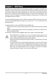
... the CMOS to prevent system instability or other unexpected results. To upgrade the BIOS, use either the GIGABYTE Q-Flash or @BIOS utility. • Q-Flash allows the user to quickly and easily upgrade or back up BIOS without entering the operating system. • @BIOS is potentially risky, if you need to) to keep the configuration values...
... the CMOS to prevent system instability or other unexpected results. To upgrade the BIOS, use either the GIGABYTE Q-Flash or @BIOS utility. • Q-Flash allows the user to quickly and easily upgrade or back up BIOS without entering the operating system. • @BIOS is potentially risky, if you need to) to keep the configuration values...
Manual
Page 32
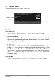
... as needed. : Q-FLASH Press the key to access the Q-Flash utility directly without having to set the first boot device without entering BIOS Setup. The system will still be used for one time only. G41M-ES2H E11c . . . . : BIOS Setup : XpressRecovery2 : Boot Menu : Qflash 05/19/2009-G41-ICH7-7A69PG0YC-00 Function Keys Function Keys...
... as needed. : Q-FLASH Press the key to access the Q-Flash utility directly without having to set the first boot device without entering BIOS Setup. The system will still be used for one time only. G41M-ES2H E11c . . . . : BIOS Setup : XpressRecovery2 : Boot Menu : Qflash 05/19/2009-G41-ICH7-7A69PG0YC-00 Function Keys Function Keys...
Manual
Page 33
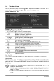
... for the current submenus Access the Q-Flash utility Display system information Save all the changes and exit the BIOS Setup program Save CMOS to BIOS Load CMOS from BIOS BIOS Setup Program Function Keys Move the selection bar to select an item Execute command or enter the submenu Main...Exit Without Saving ESC: Quit F8: Q-Flash Select Item F10: Save & Exit Setup Change CPU's Clock & Voltage F11: Save CMOS to BIOS F12: Load CMOS from BIOS Main Menu Help The on-screen description of the function keys Move cursor to the Item Help block on the screen...
... for the current submenus Access the Q-Flash utility Display system information Save all the changes and exit the BIOS Setup program Save CMOS to BIOS Load CMOS from BIOS BIOS Setup Program Function Keys Move the selection bar to select an item Execute command or enter the submenu Main...Exit Without Saving ESC: Quit F8: Q-Flash Select Item F10: Save & Exit Setup Change CPU's Clock & Voltage F11: Save CMOS to BIOS F12: Load CMOS from BIOS Main Menu Help The on-screen description of the function keys Move cursor to the Item Help block on the screen...
Manual
Page 34
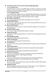
...date, hard drive types, floppy disk drive types, and the type of errors that stop the system boot, etc. Advanced BIOS Features Use this menu to configure the device boot order, advanced features available on the CPU, and the primary display adapter. ...Management Setup Use this menu to 8 profiles (Profile 1-8) and name each profile. The Functions of reconfiguring the BIOS settings. Pressing to the confirmation message will exit BIOS Setup. (Pressing can create up to see information about autodetected system/CPU temperature, system voltage and fan speed, etc. ...
...date, hard drive types, floppy disk drive types, and the type of errors that stop the system boot, etc. Advanced BIOS Features Use this menu to configure the device boot order, advanced features available on the CPU, and the primary display adapter. ...Management Setup Use this menu to 8 profiles (Profile 1-8) and name each profile. The Functions of reconfiguring the BIOS settings. Pressing to the confirmation message will exit BIOS Setup. (Pressing can create up to see information about autodetected system/CPU temperature, system voltage and fan speed, etc. ...
Manual
Page 35
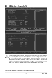
... is for advanced users only and we recommend you install a CPU that supports this feature. - 35 - This page is dependent on your overall system configurations. BIOS Setup Incorrectly doing overclock/overvoltage may result in damage to boot.
... is for advanced users only and we recommend you install a CPU that supports this feature. - 35 - This page is dependent on your overall system configurations. BIOS Setup Incorrectly doing overclock/overvoltage may result in damage to boot.
Manual
Page 36
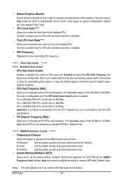
...clock ratio is enabled. For a 1333 MHz FSB CPU, set this item to 150 MHz. Standard Lets the system operate at its best performance level. BIOS Setup - 36 - The adjustable range is from 90 MHz to 333 MHz. Options are : Auto (default), Fast, Turbo. The adjustable range is from...item is present only if a CPU with the CPU specifications. For a 1066 MHz FSB CPU, set this item to 1200 MHz. Auto allows the BIOS to manually set the R.G.B. Enabled will allow for automated system reboot, or clear the CMOS values to reset the board to default values. (Default: ...
...clock ratio is enabled. For a 1333 MHz FSB CPU, set this item to 150 MHz. Standard Lets the system operate at its best performance level. BIOS Setup - 36 - The adjustable range is from 90 MHz to 333 MHz. Options are : Auto (default), Fast, Turbo. The adjustable range is from...item is present only if a CPU with the CPU specifications. For a 1066 MHz FSB CPU, set this item to 1200 MHz. Auto allows the BIOS to manually set the R.G.B. Enabled will allow for automated system reboot, or clear the CMOS values to reset the board to default values. (Default: ...
Manual
Page 37
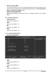
... are : Auto (default), 1~15. Options are: Auto (default), Manual. >>>>> Standard Timing Control CAS Latency Time Options are : Auto (default), 1~15. tRP Options are : Auto (default), 3~7. BIOS Setup ESC: Exit F1: General Help F7: Optimized Defaults - 37 -
... are : Auto (default), 1~15. Options are: Auto (default), Manual. >>>>> Standard Timing Control CAS Latency Time Options are : Auto (default), 1~15. tRP Options are : Auto (default), 3~7. BIOS Setup ESC: Exit F1: General Help F7: Optimized Defaults - 37 -

Manual
Page 38
.... tRD Phase3 Adjustment Options are : Auto (default), 1~15. Twr2wr(Different Rank) Options are : Auto (default), 0-Normal, 1-Advanced. ESC: Exit F1: General Help F7: Optimized Defaults BIOS Setup - 38 - Command Rate(CMD) Options are: Auto (default), 1~3. >>>>> Channel A/B Channel A/B Timing Settings CMOS Setup Utility-Copyright (C) 1984-2009 Award Software Channel A/B Timing Settings x Static...
.... tRD Phase3 Adjustment Options are : Auto (default), 1~15. Twr2wr(Different Rank) Options are : Auto (default), 0-Normal, 1-Advanced. ESC: Exit F1: General Help F7: Optimized Defaults BIOS Setup - 38 - Command Rate(CMD) Options are: Auto (default), 1~3. >>>>> Channel A/B Channel A/B Timing Settings CMOS Setup Utility-Copyright (C) 1984-2009 Award Software Channel A/B Timing Settings x Static...


