Manual
Page 4
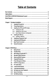
... ...6 OptionalItems...6 GA-EP45C-UD3R/UD3 Motherboard Layout 7 Block Diagram...8 Chapter 1 Hardware Installation 9 1-1 Installation Precautions 9 1-2 Product Specifications 10 1-3 Installing the CPU and CPU Cooler 13 1-3-1 Installing the CPU 13 1-3-2 Installing the CPU Cooler 15 1-4-1 Dual Channel Memory Configuration 16 1-4 Installing the Memory 16 1-4-2 Installing a Memory 17 1-5 Installing an Expansion Card 18 1-6 Installing the SATA Bracket 19 1-7 Back Panel Connectors 20 1-8 Internal Connectors 22 Chapter 2 BIOS Setup 35 2-1 Startup Screen 36 2-2 The Main Menu 37 2-3 MB...
... ...6 OptionalItems...6 GA-EP45C-UD3R/UD3 Motherboard Layout 7 Block Diagram...8 Chapter 1 Hardware Installation 9 1-1 Installation Precautions 9 1-2 Product Specifications 10 1-3 Installing the CPU and CPU Cooler 13 1-3-1 Installing the CPU 13 1-3-2 Installing the CPU Cooler 15 1-4-1 Dual Channel Memory Configuration 16 1-4 Installing the Memory 16 1-4-2 Installing a Memory 17 1-5 Installing an Expansion Card 18 1-6 Installing the SATA Bracket 19 1-7 Back Panel Connectors 20 1-8 Internal Connectors 22 Chapter 2 BIOS Setup 35 2-1 Startup Screen 36 2-2 The Main Menu 37 2-3 MB...
Manual
Page 10
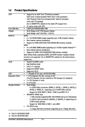
... GA-EP45C-UD3R. Support for SATA RAID 0, RAID 1, and JBOD iTE IT8718 chip: - 1 x floppy disk drive connector supporting up to 6 SATA 3Gb/s devices - Only for DDR3 2000/1600/13331066/800 MHz memory modules DDR2: 4 x 1.8V DDR2 DIMM sockets supporting up to 2 SATA 3Gb/s devices - 1-2 Product Specifications CPU Front Side Bus Chipset Memory Audio LAN Expansion Slots Storage Interface Support for an Intel® CoreTM 2 Extreme processor/ Intel® CoreTM 2 Quad processor/Intel® CoreTM 2 Duo processor/ Intel® Pentium® Dual-Core processor...
... GA-EP45C-UD3R. Support for SATA RAID 0, RAID 1, and JBOD iTE IT8718 chip: - 1 x floppy disk drive connector supporting up to 6 SATA 3Gb/s devices - Only for DDR3 2000/1600/13331066/800 MHz memory modules DDR2: 4 x 1.8V DDR2 DIMM sockets supporting up to 2 SATA 3Gb/s devices - 1-2 Product Specifications CPU Front Side Bus Chipset Memory Audio LAN Expansion Slots Storage Interface Support for an Intel® CoreTM 2 Extreme processor/ Intel® CoreTM 2 Quad processor/Intel® CoreTM 2 Duo processor/ Intel® Pentium® Dual-Core processor...

Manual
Page 16
...; Flex Memory Technology offers greater flexibility to upgrade by allowing different memory sizes to be enabled if only one direction. 1-4 Installing the Memory Read the following guidelines before you are unable to insert the memory, switch the direction. • Mixed mode, populating DDR2 and DDR3 memory modules simultaneously is not supported. 1-4-1 Dual Channel Memory Configuration This motherboard provides four DDR2 and two DDR3 memory sockets and supports Dual Channel Technology. DS/SS - - - - When enabling Dual Channel mode with...
...; Flex Memory Technology offers greater flexibility to upgrade by allowing different memory sizes to be enabled if only one direction. 1-4 Installing the Memory Read the following guidelines before you are unable to insert the memory, switch the direction. • Mixed mode, populating DDR2 and DDR3 memory modules simultaneously is not supported. 1-4-1 Dual Channel Memory Configuration This motherboard provides four DDR2 and two DDR3 memory sockets and supports Dual Channel Technology. DS/SS - - - - When enabling Dual Channel mode with...
Manual
Page 18
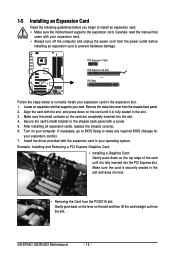
... the motherboard supports the expansion card. Install the driver provided with a screw. 5. Locate an expansion slot that came with the slot, and press down on your expansion card. • Always turn off the computer and unplug the power cord from the chassis back panel. 2. Example: Installing and Removing a PCI Express Graphics Card: • Installing a Graphics Card: Gently push down on the slot and then lift the card straight out from the slot. PCI Express x1 Slot PCI Express x16 Slot PCI Slot Follow...
... the motherboard supports the expansion card. Install the driver provided with a screw. 5. Locate an expansion slot that came with the slot, and press down on your expansion card. • Always turn off the computer and unplug the power cord from the chassis back panel. 2. Example: Installing and Removing a PCI Express Graphics Card: • Installing a Graphics Card: Gently push down on the slot and then lift the card straight out from the slot. PCI Express x1 Slot PCI Express x16 Slot PCI Slot Follow...

Manual
Page 27
... device unable to work or even damage it. Incorrect connection between the module connector and the motherboard header will be used to connect a system power LED on when the system is operating. Definition Pin No. If your chassis front panel audio module to this header. If you want to mute the back panel audio (only supported when using an HD front panel audio module), refer to Chapter 5, "Configuring 2/4/5.1/7.1-Channel Audio." • Some chassis provide a front panel audio...
... device unable to work or even damage it. Incorrect connection between the module connector and the motherboard header will be used to connect a system power LED on when the system is operating. Definition Pin No. If your chassis front panel audio module to this header. If you want to mute the back panel audio (only supported when using an HD front panel audio module), refer to Chapter 5, "Configuring 2/4/5.1/7.1-Channel Audio." • Some chassis provide a front panel audio...
Manual
Page 33
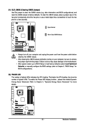
... Short: Clear CMOS Values • Always turn off your computer, be sure to touch the two pins for a few seconds. Failure to do so may cause damage to the motherboard. • After system restart, go to BIOS Setup to load factory defaults (select Load Optimized Defaults) or manually configure the BIOS settings (refer to Chapter 4, "Dynamic Energy Saver Advanced," for BIOS configurations). 22) PHASE LED The number of lighted LEDs. To enable the...
... Short: Clear CMOS Values • Always turn off your computer, be sure to touch the two pins for a few seconds. Failure to do so may cause damage to the motherboard. • After system restart, go to BIOS Setup to load factory defaults (select Load Optimized Defaults) or manually configure the BIOS settings (refer to Chapter 4, "Dynamic Energy Saver Advanced," for BIOS configurations). 22) PHASE LED The number of lighted LEDs. To enable the...
Manual
Page 36
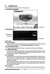
... Boot Menu, press . GA-EP45C-UD3R/UD3 Motherboard - 36 - The LOGO Screen (Default) Function Keys B. In Boot Menu, use the up hard drive data using the driver disk, the key can access Boot Menu again to change the first boot device setting as needed. : Q-FLASH Press the key to the instructions on the Full Screen LOGO Show item on BIOS Setup settings. Note: The setting in Boot Menu. After system restart, the device boot order will directly boot from the device configured in Boot Menu is effective for subsequent access to show the BIOS POST screen...
... Boot Menu, press . GA-EP45C-UD3R/UD3 Motherboard - 36 - The LOGO Screen (Default) Function Keys B. In Boot Menu, use the up hard drive data using the driver disk, the key can access Boot Menu again to change the first boot device setting as needed. : Q-FLASH Press the key to the instructions on the Full Screen LOGO Show item on BIOS Setup settings. Note: The setting in Boot Menu. After system restart, the device boot order will directly boot from the device configured in Boot Menu is effective for subsequent access to show the BIOS POST screen...
Manual
Page 38
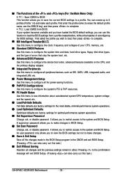
... CPU, and the primary display adapter. „ Integrated Peripherals Use this menu to configure all peripheral devices, such as IDE, SATA, USB, integrated audio, and integrated LAN, etc. „ Power Management Setup Use this menu to configure all the power-saving functions. „ PnP/PCI Configurations Use this menu to configure the system's PCI & PnP resources. „ PC Health Status Use this menu to see information about autodetected system/CPU temperature, system voltage and fan speed, etc. „ Load Fail-Safe Defaults Fail-Safe defaults...
... CPU, and the primary display adapter. „ Integrated Peripherals Use this menu to configure all peripheral devices, such as IDE, SATA, USB, integrated audio, and integrated LAN, etc. „ Power Management Setup Use this menu to configure all the power-saving functions. „ PnP/PCI Configurations Use this menu to configure the system's PCI & PnP resources. „ PC Health Status Use this menu to see information about autodetected system/CPU temperature, system voltage and fan speed, etc. „ Load Fail-Safe Defaults Fail-Safe defaults...
Manual
Page 40
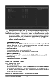
If this feature. CPU Frequency Displays the current operating CPU frequency. ******** Clock Chip Control Standard Clock Control CPU Host Clock Control Enables or disables the control of these components. GA-EP45C-UD3R/UD3 Motherboard - 40 - Incorrectly doing overclock/overvoltage may result in system's failure to boot. The item is present only if a CPU with the overclock/overvoltage settings you made is dependent on system configurations. Options are: Auto (default), Fast, Turbo. Enabled will work stably with unlocked clock ratio is for advanced users only and...
If this feature. CPU Frequency Displays the current operating CPU frequency. ******** Clock Chip Control Standard Clock Control CPU Host Clock Control Enables or disables the control of these components. GA-EP45C-UD3R/UD3 Motherboard - 40 - Incorrectly doing overclock/overvoltage may result in system's failure to boot. The item is present only if a CPU with the overclock/overvoltage settings you made is dependent on system configurations. Options are: Auto (default), Fast, Turbo. Enabled will work stably with unlocked clock ratio is for advanced users only and...

Manual
Page 48
... error during the POST for faster system startup. • Manual Allows you to selects the type of floppy disk drive installed in your hard drive specifications. Base Memory Also called conventional memory. Extended Memory The amount of heads. Options are : Disabled (default), Drive A. All, But Disk/Key The system boot will not stop for a keyboard or a floppy disk drive error but stop for all other errors. • Auto • None Lets BIOS automatically detect IDE/SATA devices during the POST. (Default) If no IDE/SATA devices are used , set...
... error during the POST for faster system startup. • Manual Allows you to selects the type of floppy disk drive installed in your hard drive specifications. Base Memory Also called conventional memory. Extended Memory The amount of heads. Options are : Disabled (default), Drive A. All, But Disk/Key The system boot will not stop for a keyboard or a floppy disk drive error but stop for all other errors. • Auto • None Lets BIOS automatically detect IDE/SATA devices during the POST. (Default) If no IDE/SATA devices are used , set...

Manual
Page 49
... password(s) under the Set Supervisor/User Password item in the BIOS Main Menu. Use the up or down arrow key to select a device and press to 3 (Note) No-Execute Memory Protect (Note) CPU Enhanced Halt (C1E) (Note) C2/C2E State Support (Note) C4/C4E State Support (Note) CPU Thermal Monitor 2(TM2) (Note) CPU EIST Function (Note) Virtualization Technology (Note) Delay For HDD (Secs) Full Screen LOGO Show Init Display First [Press Enter] [Floppy] [Hard Disk] [CDROM] [Setup] [Enabled] [Enabled] [Disabled] [Enabled] [Enabled] [Disabled] Disabled [Enabled] [Enabled] [Enabled] [0] [Enabled] [PCI...
... password(s) under the Set Supervisor/User Password item in the BIOS Main Menu. Use the up or down arrow key to select a device and press to 3 (Note) No-Execute Memory Protect (Note) CPU Enhanced Halt (C1E) (Note) C2/C2E State Support (Note) C4/C4E State Support (Note) CPU Thermal Monitor 2(TM2) (Note) CPU EIST Function (Note) Virtualization Technology (Note) Delay For HDD (Secs) Full Screen LOGO Show Init Display First [Press Enter] [Floppy] [Hard Disk] [CDROM] [Setup] [Enabled] [Enabled] [Disabled] [Enabled] [Enabled] [Disabled] Disabled [Enabled] [Enabled] [Enabled] [0] [Enabled] [PCI...

Manual
Page 52
... hot plug. GA-EP45C-UD3R/UD3 Motherboard - 52 - 2-6 Integrated Peripherals CMOS Setup Utility-Copyright (C) 1984-2008 Award Software SATA RAID/AHCI Mode 1 SATA AHCI Mode 2 SATA Port0-3 Native Mode Azalia Codec Onboard H/W 1394 Onboard H/W LAN Green LAN ` SMART LAN Onboard LAN Boot ROM Onboard SATA/IDE Device Onboard SATA/IDE Ctrl Mode Onboard Serial Port 1 Onboard Parallel Port Parallel Port Mode USB 1.0 Controller USB 2.0 Controller USB Keyboard Function USB Mouse Function USB Storage Function [Disabled] [Disabled] [Disabled] [Auto] [Enabled] [Enabled] [Disbabled] [Press Enter] [Disabled...
... hot plug. GA-EP45C-UD3R/UD3 Motherboard - 52 - 2-6 Integrated Peripherals CMOS Setup Utility-Copyright (C) 1984-2008 Award Software SATA RAID/AHCI Mode 1 SATA AHCI Mode 2 SATA Port0-3 Native Mode Azalia Codec Onboard H/W 1394 Onboard H/W LAN Green LAN ` SMART LAN Onboard LAN Boot ROM Onboard SATA/IDE Device Onboard SATA/IDE Ctrl Mode Onboard Serial Port 1 Onboard Parallel Port Parallel Port Mode USB 1.0 Controller USB 2.0 Controller USB Keyboard Function USB Mouse Function USB Storage Function [Disabled] [Disabled] [Disabled] [Auto] [Enabled] [Enabled] [Disbabled] [Press Enter] [Disabled...

Manual
Page 54
... to AHCI mode. Enables RAID for the SATA controller and configures the SATA controller to PATA mode. (Default) AHCI Configures the SATA controller to detect USB storage devices, including USB flash drives and USB hard drives during the POST. (Default: Enabled) GA-EP45C-UD3R/UD3 Motherboard - 54 - USB 2.0 Controller Enables or disables the integrated USB 2.0 controller. (Default: Enabled) USB Keyboard Function Allows USB keyboard to be used in MS-DOS. (Default: Disabled) USB Mouse Function Allows USB mouse to be the approximate distance to the fault or short. Options are...
... to AHCI mode. Enables RAID for the SATA controller and configures the SATA controller to PATA mode. (Default) AHCI Configures the SATA controller to detect USB storage devices, including USB flash drives and USB hard drives during the POST. (Default: Enabled) GA-EP45C-UD3R/UD3 Motherboard - 54 - USB 2.0 Controller Enables or disables the integrated USB 2.0 controller. (Default: Enabled) USB Keyboard Function Allows USB keyboard to be used in MS-DOS. (Default: Disabled) USB Mouse Function Allows USB mouse to be the approximate distance to the fault or short. Options are...

Manual
Page 73
... monitor will display the update process. • Do not turn off or restart the system when the system is reading/updating the BIOS. • Do not remove the floppy disk, USB flash drive, or hard drive when the system is saved to a hard drive in RAID/AHCI mode or a hard drive attached to an independent IDE/SATA controller, use the up or down arrow key to select Update BIOS from Drive Sa0vefilBeI(Os)SfotounDdrive KL:Move ESC:Reset :Power Off Total size : 0 Free size...
... monitor will display the update process. • Do not turn off or restart the system when the system is reading/updating the BIOS. • Do not remove the floppy disk, USB flash drive, or hard drive when the system is saved to a hard drive in RAID/AHCI mode or a hard drive attached to an independent IDE/SATA controller, use the up or down arrow key to select Update BIOS from Drive Sa0vefilBeI(Os)SfotounDdrive KL:Move ESC:Reset :Power Off Total size : 0 Free size...
Manual
Page 76
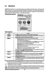
... Monitor tab allows you to change system clock settings and voltages settings using the sliders. • Save allows you to save the current settings to a new profile (.txt file). • Load allows you set temperature/fan speed alarm. Grayed-out area(s) indicates that you must install an Intel® CoreTM 2 Extreme/ CoreTM2 Quad/ CoreTM2 Duo/ Pentium Dual-Core/ Celeron Dual-Core Series CPU and DDR2 800 MHz memory module(s) (or above) to enable support...
... Monitor tab allows you to change system clock settings and voltages settings using the sliders. • Save allows you to save the current settings to a new profile (.txt file). • Load allows you set temperature/fan speed alarm. Grayed-out area(s) indicates that you must install an Intel® CoreTM 2 Extreme/ CoreTM2 Quad/ CoreTM2 Duo/ Pentium Dual-Core/ Celeron Dual-Core Series CPU and DDR2 800 MHz memory module(s) (or above) to enable support...

Manual
Page 82
...have and the BIOS version. To create RAID, set this section may differ from the exact settings for your computer and press to configure the SATA controller mode correctly in this item to RAID (Figure 1)(Disabled by default). If you will see shall depend on your motherboard. CMOS Setup Utility-Copyright (C) 1984-2008 Award Software SATA RAID/AHCI Mode SATA Port0-3 Native Mode Azalia Codec Onboard H/W 1394 Onboard H/W LAN Green LAN ` SMART LAN Onboard LAN Boot ROM Onboard SATA/IDE Device Onboard SATA/IDE Ctrl Mode Onboard Serial Port 1 Onboard Parallel Port Parallel Port Mode USB...
...have and the BIOS version. To create RAID, set this section may differ from the exact settings for your computer and press to configure the SATA controller mode correctly in this item to RAID (Figure 1)(Disabled by default). If you will see shall depend on your motherboard. CMOS Setup Utility-Copyright (C) 1984-2008 Award Software SATA RAID/AHCI Mode SATA Port0-3 Native Mode Azalia Codec Onboard H/W 1394 Onboard H/W LAN Green LAN ` SMART LAN Onboard LAN Boot ROM Onboard SATA/IDE Device Onboard SATA/IDE Ctrl Mode Onboard Serial Port 1 Onboard Parallel Port Parallel Port Mode USB...
Manual
Page 87
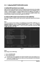
... Defaults Only for GA-EP45C-UD3. In BIOS Setup, go to RAID/IDE (Figure 1). CMOS Setup Utility-Copyright (C) 1984-2008 Award Software SATA RAID/AHCI Mode 1 SATA AHCI Mode 2 SATA Port0-3 Native Mode Azalia Codec Onboard H/W 1394 Onboard H/W LAN Green LAN ` SMART LAN Onboard LAN Boot ROM Onboard SATA/IDE Device Onboard SATA/IDE Ctrl Mode Onboard Serial Port 1 Onboard Parallel Port Parallel Port Mode USB 1.0 Controller USB 2.0 Controller USB Keyboard Function USB Mouse Function USB Storage Function [Disabled] [Disabled] [Disabled] [Auto] [Enabled] [Enabled] [Disbabled] [Press Enter...
... Defaults Only for GA-EP45C-UD3. In BIOS Setup, go to RAID/IDE (Figure 1). CMOS Setup Utility-Copyright (C) 1984-2008 Award Software SATA RAID/AHCI Mode 1 SATA AHCI Mode 2 SATA Port0-3 Native Mode Azalia Codec Onboard H/W 1394 Onboard H/W LAN Green LAN ` SMART LAN Onboard LAN Boot ROM Onboard SATA/IDE Device Onboard SATA/IDE Ctrl Mode Onboard Serial Port 1 Onboard Parallel Port Parallel Port Mode USB 1.0 Controller USB 2.0 Controller USB Keyboard Function USB Mouse Function USB Storage Function [Disabled] [Disabled] [Disabled] [Auto] [Enabled] [Enabled] [Disbabled] [Press Enter...
Manual
Page 88
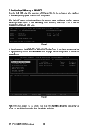
... Type/Status Non-RAID Non-RAID [ RAID Disk Drive List ] [IJTAB]-Switch Window [KL]-Select ITEM [ENTER]-Action Figure 3 [ESC]-Exit Note: In the main screen, you wish to the installation of the GIGABYTE SATA2 RAID BIOS utility (Figure 3), use the up or down arrow key to enter RAID Setup Utility ... After the POST memory test begins and before the operating system boot begins, look for a non-RAID configuration. GA-EP45C-UD3R/UD3 Motherboard - 88 - PCIE-to enter the GIGABYTE SATA2 RAID BIOS utility. GIGABYTE Technology Corp. Press + to -SATAII/IDE RAID Controller BIOS...
... Type/Status Non-RAID Non-RAID [ RAID Disk Drive List ] [IJTAB]-Switch Window [KL]-Select ITEM [ENTER]-Action Figure 3 [ESC]-Exit Note: In the main screen, you wish to the installation of the GIGABYTE SATA2 RAID BIOS utility (Figure 3), use the up or down arrow key to enter RAID Setup Utility ... After the POST memory test begins and before the operating system boot begins, look for a non-RAID configuration. GA-EP45C-UD3R/UD3 Motherboard - 88 - PCIE-to enter the GIGABYTE SATA2 RAID BIOS utility. GIGABYTE Technology Corp. Press + to -SATAII/IDE RAID Controller BIOS...

Manual
Page 94
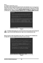
... Vista installation. Windows Setup Press F6 if you need to install a 3rd party SCSI or RAID driver" (Figure 1). 5-1-4 Installing the SATA RAID/AHCI Driver and Operating System Now that below appears, insert the floppy disk containing the SATA RAID/AHCI driver and press (Figure 2). Installing Windows XP Step 1: Restart your hard drive(s). S=Specify Additional Device ENTER=Continue F3=Exit Figure 2 GA-EP45C-UD3R/UD3 Motherboard - 94 - After pressing , there will load support for use with Windows, press ENTER. A. Windows Setup Setup could not determine the type...
... Vista installation. Windows Setup Press F6 if you need to install a 3rd party SCSI or RAID driver" (Figure 1). 5-1-4 Installing the SATA RAID/AHCI Driver and Operating System Now that below appears, insert the floppy disk containing the SATA RAID/AHCI driver and press (Figure 2). Installing Windows XP Step 1: Restart your hard drive(s). S=Specify Additional Device ENTER=Continue F3=Exit Figure 2 GA-EP45C-UD3R/UD3 Motherboard - 94 - After pressing , there will load support for use with Windows, press ENTER. A. Windows Setup Setup could not determine the type...
Manual
Page 96
... the GIGABYTE SATA2 SATA RAID/AHCI driver in the floppy disk, a controller menu similar to Figure 5 below appears, press to continue the driver installation from a mass storage device manufacturer, or do not have any device support disks from the floppy disk. Use the arrow keys to RAID or AHCI mode, select (Windows XP/2003) RAID/AHCI Driver for use with Windows, including those for which you have chosen to configure a SCSI Adapter for GIGABYTE GBB36X Controller. If you set the Onboard SATA/IDE Ctrl Mode item in BIOS Setup...
... the GIGABYTE SATA2 SATA RAID/AHCI driver in the floppy disk, a controller menu similar to Figure 5 below appears, press to continue the driver installation from a mass storage device manufacturer, or do not have any device support disks from the floppy disk. Use the arrow keys to RAID or AHCI mode, select (Windows XP/2003) RAID/AHCI Driver for use with Windows, including those for which you have chosen to configure a SCSI Adapter for GIGABYTE GBB36X Controller. If you set the Onboard SATA/IDE Ctrl Mode item in BIOS Setup...


