Manual
Page 1
GA-EP45C-UD3R/ GA-EP45C-UD3 LGA775 socket motherboard for Intel® CoreTM processor family/ Intel® Pentium® processor family/Intel® Celeron® processor family User's Manual Rev. 1001 12ME-EP45CUD3R-1001R
GA-EP45C-UD3R/ GA-EP45C-UD3 LGA775 socket motherboard for Intel® CoreTM processor family/ Intel® Pentium® processor family/Intel® Celeron® processor family User's Manual Rev. 1001 12ME-EP45CUD3R-1001R

Manual
Page 2
Motherboard GA-EP45C-UD3R/GA-EP45C-UD3 Oct. 22, 2008 Motherboard GA-EP45C-UD3R/ GA-EP45C-UD3 Oct. 22, 2008
Motherboard GA-EP45C-UD3R/GA-EP45C-UD3 Oct. 22, 2008 Motherboard GA-EP45C-UD3R/ GA-EP45C-UD3 Oct. 22, 2008
Manual
Page 4
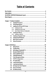
Table of Contents Box Contents ...6 OptionalItems...6 GA-EP45C-UD3R/UD3 Motherboard Layout 7 Block Diagram...8 Chapter 1 Hardware Installation 9 1-1 Installation Precautions 9 1-2 Product Specifications 10 1-3 Installing the CPU and CPU Cooler 13 1-3-1 Installing the CPU 13 1-3-2 Installing the ...
Table of Contents Box Contents ...6 OptionalItems...6 GA-EP45C-UD3R/UD3 Motherboard Layout 7 Block Diagram...8 Chapter 1 Hardware Installation 9 1-1 Installation Precautions 9 1-2 Product Specifications 10 1-3 Installing the CPU and CPU Cooler 13 1-3-1 Installing the CPU 13 1-3-2 Installing the ...
Manual
Page 6
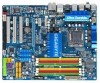
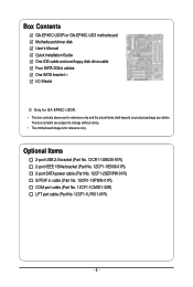
Box Contents GA-EP45C-UD3R or GA-EP45C-UD3 motherboard Motherboard driver disk User's Manual Quick Installation Guide One IDE cable and one floppy disk drive cable Four SATA 3Gb/s cables One SATA bracket I/O Shield Only for GA-EP45C-UD3R. • The box contents above are subject to change without notice. • The motherboard image is for reference only and...
Box Contents GA-EP45C-UD3R or GA-EP45C-UD3 motherboard Motherboard driver disk User's Manual Quick Installation Guide One IDE cable and one floppy disk drive cable Four SATA 3Gb/s cables One SATA bracket I/O Shield Only for GA-EP45C-UD3R. • The box contents above are subject to change without notice. • The motherboard image is for reference only and...
Manual
Page 7
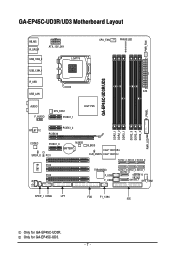
Only for GA-EP45C-UD3R. GA-EP45C-UD3R/UD3 Motherboard Layout PWR_FAN KB_MS R_SPDIF ATX_12V_2X4 USB_1394_2 LGA775 USB_1394_1 R_USB USB_LAN CPU_FAN PHASE LED ATX GA-EP45C-UD3R/UD3 F_PANEL AUDIO F_AUDIO SYS_FAN1 ...PCIEX1_1 Intel® P45 DDR2_1 DDR2_2 DDR3_1 DDR2_3 DDR2_4 DDR3_2 PWR_LED RTL8111C PCIEX16 PCIEX1_2 CODEC SPDIF_O IT8718 CI PCIEX1_3 M_BIOS BATTERY PCI1 PCI2 PCI3 B_BIOS Intel® ICH10R CLR_CMOS Intel® ICH10 SATA2_4 SATA2_2 SATA2_0 TSB43AB23 F_USB1 F_USB2 SATA2_5 SATA2_3 SATA2_1 GSATA2_0 GIGABYTE...
Only for GA-EP45C-UD3R. GA-EP45C-UD3R/UD3 Motherboard Layout PWR_FAN KB_MS R_SPDIF ATX_12V_2X4 USB_1394_2 LGA775 USB_1394_1 R_USB USB_LAN CPU_FAN PHASE LED ATX GA-EP45C-UD3R/UD3 F_PANEL AUDIO F_AUDIO SYS_FAN1 ...PCIEX1_1 Intel® P45 DDR2_1 DDR2_2 DDR3_1 DDR2_3 DDR2_4 DDR3_2 PWR_LED RTL8111C PCIEX16 PCIEX1_2 CODEC SPDIF_O IT8718 CI PCIEX1_3 M_BIOS BATTERY PCI1 PCI2 PCI3 B_BIOS Intel® ICH10R CLR_CMOS Intel® ICH10 SATA2_4 SATA2_2 SATA2_0 TSB43AB23 F_USB1 F_USB2 SATA2_5 SATA2_3 SATA2_1 GSATA2_0 GIGABYTE...

Manual
Page 8
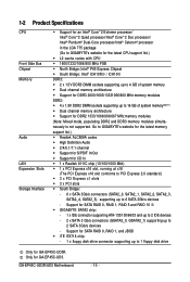
... CLK (100 MHz) x1 x1 x1 PCI Express Bus LAN RJ45 RTL 8111C x1 2 SATA 3Gb/s ATA-133/100/66/ 33 IDE Channel PCI Bus GIGABYTE SATA2 TSB43AB23 3 IEEE 1394a Intel® P45 Dual Channel Memory DDR3 2000/1600/1333/ 1066/800 MHz Dual Channel Memory MCH CLK (400/333/266... Speaker Out Center/Subwoofer Speaker Out Side Speaker Out MIC Line-Out Line-In SPDIF In SPDIF Out 3 PCI PCI CLK (33 MHz) Only for GA-EP45C-UD3. - 8 - Only for GA-EP45C-UD3R.
... CLK (100 MHz) x1 x1 x1 PCI Express Bus LAN RJ45 RTL 8111C x1 2 SATA 3Gb/s ATA-133/100/66/ 33 IDE Channel PCI Bus GIGABYTE SATA2 TSB43AB23 3 IEEE 1394a Intel® P45 Dual Channel Memory DDR3 2000/1600/1333/ 1066/800 MHz Dual Channel Memory MCH CLK (400/333/266... Speaker Out Center/Subwoofer Speaker Out Side Speaker Out MIC Line-Out Line-In SPDIF In SPDIF Out 3 PCI PCI CLK (33 MHz) Only for GA-EP45C-UD3. - 8 - Only for GA-EP45C-UD3R.
Manual
Page 10
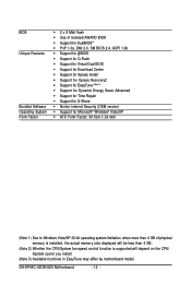
... Only for DDR2 1333/1066/800/667 MHz memory modules (Note: Mixed mode, populating DDR2 and DDR3 memory modules simultaneously is not supported. GA-EP45C-UD3R/UD3 Motherboard - 10 - Go to GIGABYTE's website for the latest memory support list.) Realtek ALC889A codec High Definition Audio 2/4/5.1/7.1-channel Support for S/PDIF In/Out...
... Only for DDR2 1333/1066/800/667 MHz memory modules (Note: Mixed mode, populating DDR2 and DDR3 memory modules simultaneously is not supported. GA-EP45C-UD3R/UD3 Motherboard - 10 - Go to GIGABYTE's website for the latest memory support list.) Realtek ALC889A codec High Definition Audio 2/4/5.1/7.1-channel Support for S/PDIF In/Out...
Manual
Page 12
GA-EP45C-UD3R/UD3 Motherboard - 12 - BIOS Unique Features Bundled Software Operating System Form Factor Š 2 x 8 Mbit flash Š Use of licensed AWARD BIOS Š Support for DualBIOSTM Š ...
GA-EP45C-UD3R/UD3 Motherboard - 12 - BIOS Unique Features Bundled Software Operating System Form Factor Š 2 x 8 Mbit flash Š Use of licensed AWARD BIOS Š Support for DualBIOSTM Š ...
Manual
Page 14
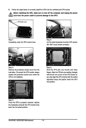
... with the socket alignment keys) and gently insert the CPU into the motherboard CPU socket. CPU Socket Lever Step 1: Completely raise the CPU socket lever. GA-EP45C-UD3R/UD3 Motherboard - 14 -
... with the socket alignment keys) and gently insert the CPU into the motherboard CPU socket. CPU Socket Lever Step 1: Completely raise the CPU socket lever. GA-EP45C-UD3R/UD3 Motherboard - 14 -

Manual
Page 16
... mode. 1. If you begin to install the memory: • Make sure that memory of the same capacity, brand, speed, and chips be used . (Go to GIGABYTE's website for optimum performance. When memory modules of different capacity and chips are divided into two channels and each channel has two memory sockets as... installed in Flex Memory Mode will double the original memory bandwidth. When enabling Dual Channel mode with two or four memory modules, it is installed. 2. GA-EP45C-UD3R/UD3 Motherboard - 16 -
... mode. 1. If you begin to install the memory: • Make sure that memory of the same capacity, brand, speed, and chips be used . (Go to GIGABYTE's website for optimum performance. When memory modules of different capacity and chips are divided into two channels and each channel has two memory sockets as... installed in Flex Memory Mode will double the original memory bandwidth. When enabling Dual Channel mode with two or four memory modules, it is installed. 2. GA-EP45C-UD3R/UD3 Motherboard - 16 -
Manual
Page 18
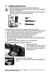
... is fully seated in your operating system. PCI Express x1 Slot PCI Express x16 Slot PCI Slot Follow the steps below to prevent hardware damage. GA-EP45C-UD3R/UD3 Motherboard - 18 - Locate an expansion slot that came with a screw. 5. Align the card with the expansion card in the slot. 3. If necessary, go to BIOS...
... is fully seated in your operating system. PCI Express x1 Slot PCI Express x16 Slot PCI Slot Follow the steps below to prevent hardware damage. GA-EP45C-UD3R/UD3 Motherboard - 18 - Locate an expansion slot that came with a screw. 5. Align the card with the expansion card in the slot. 3. If necessary, go to BIOS...
Manual
Page 20
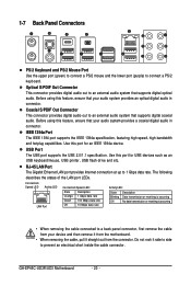
..., first remove the cable from the connector. Before using this port for an IEEE 1394a device. Use this feature, ensure that supports digital optical audio. GA-EP45C-UD3R/UD3 Motherboard - 20 -
..., first remove the cable from the connector. Before using this port for an IEEE 1394a device. Use this feature, ensure that supports digital optical audio. GA-EP45C-UD3R/UD3 Motherboard - 20 -

Manual
Page 22
GA-EP45C-UD3R/UD3 Motherboard - 22 - 1-8 Internal Connectors 1 3 22 5 2 4 11 12 10 23 21 15 20 8 9 4 13 14 19 18 6 17 16 7 1) ATX_12V_2X4 2) ATX 3) CPU_FAN 4) SYS_FAN1/SYS_FAN2 5) PWR_FAN 6) FDD 7) ...
GA-EP45C-UD3R/UD3 Motherboard - 22 - 1-8 Internal Connectors 1 3 22 5 2 4 11 12 10 23 21 15 20 8 9 4 13 14 19 18 6 17 16 7 1) ATX_12V_2X4 2) ATX 3) CPU_FAN 4) SYS_FAN1/SYS_FAN2 5) PWR_FAN 6) FDD 7) ...
Manual
Page 24
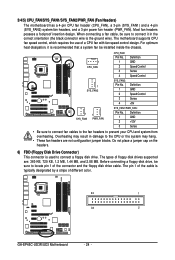
.... Do not place a jumper cap on the headers. 6) FDD (Floppy Disk Drive Connector) This connector is typically designated by a stripe of different color. 33 1 34 2 GA-EP45C-UD3R/UD3 Motherboard - 24 - The types of the connector and the floppy disk drive cable. The motherboard supports CPU fan speed control, which requires the use of...
.... Do not place a jumper cap on the headers. 6) FDD (Floppy Disk Drive Connector) This connector is typically designated by a stripe of different color. 33 1 34 2 GA-EP45C-UD3R/UD3 Motherboard - 24 - The types of the connector and the floppy disk drive cable. The motherboard supports CPU fan speed control, which requires the use of...

Manual
Page 26
... four hard drives and the total number of hard drives must be an even number. • A RAID 5 configuration requires at least two hard drives. The GIGABYTE SATA2 controller supports RAID 0 and RAID 1. GSATA2_0 7 1 1 7 GSATA2_1 Pin No. 1 2 3 4 5 6 7 Definition GND TXP TXN GND RXN RXP GND • A ... Please connect the L-shaped end of hard drives does not have to Chapter 5, "Configuring SATA Hard Drive(s)," for GA-EP45C-UD3. Each SATA connector supports a single SATA device. GA-EP45C-UD3R/UD3 Motherboard - 26 - Only for instructions on configuring a RAID array.
... four hard drives and the total number of hard drives must be an even number. • A RAID 5 configuration requires at least two hard drives. The GIGABYTE SATA2 controller supports RAID 0 and RAID 1. GSATA2_0 7 1 1 7 GSATA2_1 Pin No. 1 2 3 4 5 6 7 Definition GND TXP TXN GND RXN RXP GND • A ... Please connect the L-shaped end of hard drives does not have to Chapter 5, "Configuring SATA Hard Drive(s)," for GA-EP45C-UD3. Each SATA connector supports a single SATA device. GA-EP45C-UD3R/UD3 Motherboard - 26 - Only for instructions on configuring a RAID array.
Manual
Page 28
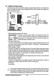
... system startup. The LED is on when the hard drive is in S1 sleep state. Speaker Power Switch Message/Power/ Sleep LED 20 19 SPEAK- GA-EP45C-UD3R/UD3 Motherboard - 28 - You may configure the way to turn off when the system is reading or writing data. • RES (Reset Switch, Green): Connects to...
... system startup. The LED is on when the hard drive is in S1 sleep state. Speaker Power Switch Message/Power/ Sleep LED 20 19 SPEAK- GA-EP45C-UD3R/UD3 Motherboard - 28 - You may configure the way to turn off when the system is reading or writing data. • RES (Reset Switch, Green): Connects to...

Manual
Page 30
... the USB bracket. Definition 1 SPDIFO 1 2 GND 16) F_USB1/F_USB2 (USB Headers, Yellow) The headers conform to certain expansion cards like graphics cards and sound cards. GA-EP45C-UD3R/UD3 Motherboard - 30 - For purchasing the optional USB bracket, please contact the local dealer. 9 1 10 2 Pin No. 1 2 3 4 5 6 7 8 9 10 Definition Power (5V) Power (5V) USB DXUSB DYUSB...
... the USB bracket. Definition 1 SPDIFO 1 2 GND 16) F_USB1/F_USB2 (USB Headers, Yellow) The headers conform to certain expansion cards like graphics cards and sound cards. GA-EP45C-UD3R/UD3 Motherboard - 30 - For purchasing the optional USB bracket, please contact the local dealer. 9 1 10 2 Pin No. 1 2 3 4 5 6 7 8 9 10 Definition Power (5V) Power (5V) USB DXUSB DYUSB...

Manual
Page 32
Pin No. Definition 1 Signal 1 2 GND GA-EP45C-UD3R/UD3 Motherboard - 32 - For purchasing the optional COM port cable, please contact the local dealer. 9 1 10 2 Pin No. 1 2 3 4 5 6 7 8 9 10 Definition NDCD NSIN NSOUT NDTR GND NDSR NRTS NCTS NRI No Pin 20) CI (Chassis Intrusion Header) This motherboard provides a chassis detection feature that detects if the chassis cover has been removed. 19) COMA (Serial Port Header) The COM header can provide one serial port via an optional COM port cable. This function requires a chassis with chassis intrusion detection design.
Pin No. Definition 1 Signal 1 2 GND GA-EP45C-UD3R/UD3 Motherboard - 32 - For purchasing the optional COM port cable, please contact the local dealer. 9 1 10 2 Pin No. 1 2 3 4 5 6 7 8 9 10 Definition NDCD NSIN NSOUT NDTR GND NDSR NRTS NCTS NRI No Pin 20) CI (Chassis Intrusion Header) This motherboard provides a chassis detection feature that detects if the chassis cover has been removed. 19) COMA (Serial Port Header) The COM header can provide one serial port via an optional COM port cable. This function requires a chassis with chassis intrusion detection design.
Manual
Page 34
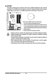
Danger of explosion if the battery is turned off. GA-EP45C-UD3R/UD3 Motherboard - 34 - 23) BATTERY The battery provides power to keep the values (such as BIOS configurations, date, and time information) in the CMOS when the ...
Danger of explosion if the battery is turned off. GA-EP45C-UD3R/UD3 Motherboard - 34 - 23) BATTERY The battery provides power to keep the values (such as BIOS configurations, date, and time information) in the CMOS when the ...
Manual
Page 36
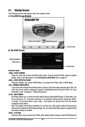
... to the instructions on the Full Screen LOGO Show item on BIOS Setup settings. Note: The setting in Boot Menu. GA-EP45C-UD3R/UD3 Motherboard - 36 - To exit Boot Menu, press . Motherboard Model BIOS Version EP45C-UD3R E9c . . . . : BIOS Setup : XpressRecovery2 : Boot Menu : Qflash 10/09/2008-P45-ICH10-7A69PG05C-00 Function Keys Function Keys: : POST...
... to the instructions on the Full Screen LOGO Show item on BIOS Setup settings. Note: The setting in Boot Menu. GA-EP45C-UD3R/UD3 Motherboard - 36 - To exit Boot Menu, press . Motherboard Model BIOS Version EP45C-UD3R E9c . . . . : BIOS Setup : XpressRecovery2 : Boot Menu : Qflash 10/09/2008-P45-ICH10-7A69PG05C-00 Function Keys Function Keys: : POST...


