Manual
Page 1
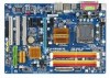
GA-EP31-DS3L LGA775 socket motherboard for Intel® CoreTM processor family/ Intel® Pentium® processor family/Intel® Celeron® processor family User's Manual Rev. 2102 12ME-EP31DS3L-2102R
GA-EP31-DS3L LGA775 socket motherboard for Intel® CoreTM processor family/ Intel® Pentium® processor family/Intel® Celeron® processor family User's Manual Rev. 2102 12ME-EP31DS3L-2102R
Manual
Page 3
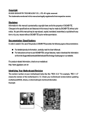
... "REV: 1.0" means the revision of the motherboard is the property of GIGABYTE. Check your motherboard looks like this: "REV: X.X." The trademarks mentioned in this manual are legally registered to their respective owners. Disclaimer Information in this manual is protected by copyright laws and is 1.0. ...this product, GIGABYTE provides the following types of this manual may be made by any form or by GIGABYTE without GIGABYTE's prior written permission. For product-related information, check on our website at: http://www.gigabyte.com.tw Identifying Your Motherboard Revision The ...
... "REV: 1.0" means the revision of the motherboard is the property of GIGABYTE. Check your motherboard looks like this: "REV: X.X." The trademarks mentioned in this manual are legally registered to their respective owners. Disclaimer Information in this manual is protected by copyright laws and is 1.0. ...this product, GIGABYTE provides the following types of this manual may be made by any form or by GIGABYTE without GIGABYTE's prior written permission. For product-related information, check on our website at: http://www.gigabyte.com.tw Identifying Your Motherboard Revision The ...
Manual
Page 6
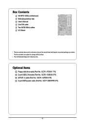
Optional Items Floppy disk drive cable (Part No. 12CF1-1FD001-7*R) 2-port USB 2.0 bracket (Part No. 12CR1-1UB030-5*R) S/PDIF in cable (Part No. 12CR1-1SPDIN-0*R) 2-port SATA power cable (Part No. 12CF1-2SERPW-0*R) - 6 - The box contents are for reference only. Box Contents GA-EP31-DS3L motherboard Motherboard driver disk User's Manual One IDE cable Two SATA 3Gb/s cables I/O Shield • The box contents above are subject to change without notice. • The motherboard image is for reference only and the actual items shall depend on product package you obtain.
Optional Items Floppy disk drive cable (Part No. 12CF1-1FD001-7*R) 2-port USB 2.0 bracket (Part No. 12CR1-1UB030-5*R) S/PDIF in cable (Part No. 12CR1-1SPDIN-0*R) 2-port SATA power cable (Part No. 12CF1-2SERPW-0*R) - 6 - The box contents are for reference only. Box Contents GA-EP31-DS3L motherboard Motherboard driver disk User's Manual One IDE cable Two SATA 3Gb/s cables I/O Shield • The box contents above are subject to change without notice. • The motherboard image is for reference only and the actual items shall depend on product package you obtain.
Manual
Page 9
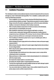
... of your hardware components are connected. • To prevent damage to the motherboard, do not have an ESD wrist strap, keep your dealer. Prior to installation, carefully read the user's manual and follow these procedures: • Prior to installation, do not remove or... break motherboard S/N (Serial Number) sticker or warranty sticker provided by unplugging the power cord from the motherboard, make sure the power supply has been turned ...
... of your hardware components are connected. • To prevent damage to the motherboard, do not have an ESD wrist strap, keep your dealer. Prior to installation, carefully read the user's manual and follow these procedures: • Prior to installation, do not remove or... break motherboard S/N (Serial Number) sticker or warranty sticker provided by unplugging the power cord from the motherboard, make sure the power supply has been turned ...

Manual
Page 15
...4: You should hear a "click" when pushing down on the motherboard. Step 6: Finally, attach the power connector of the motherboard. Check that the Male and Female push pins are joined closely. (Refer to your CPU cooler installation manual for instructions on installing the cooler.) Step 5: After the installation..., check the back of the CPU cooler to install.) Step 3: Place the cooler atop the CPU, aligning the four push pins through the pin holes on the motherboard.
...4: You should hear a "click" when pushing down on the motherboard. Step 6: Finally, attach the power connector of the motherboard. Check that the Male and Female push pins are joined closely. (Refer to your CPU cooler installation manual for instructions on installing the cooler.) Step 5: After the installation..., check the back of the CPU cooler to install.) Step 3: Place the cooler atop the CPU, aligning the four push pins through the pin holes on the motherboard.
Manual
Page 18
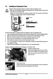
...Example: Installing and Removing a PCI Express x16 Graphics Card: • Installing a Graphics Card: Gently insert the graphics card into the slot. 4. GA-EP31-DS3L Motherboard - 18 - Turn on the card are completely inserted into the PCI Express x16 slot. Make sure the metal contacts on your expansion card in ... the card straight up from the chassis back panel. 2. Remove the metal slot cover from the slot. Carefully read the manual that supports your operating system. Install the driver provided with a screw. 5. Make sure the graphics card is fully seated in your card....
...Example: Installing and Removing a PCI Express x16 Graphics Card: • Installing a Graphics Card: Gently insert the graphics card into the slot. 4. GA-EP31-DS3L Motherboard - 18 - Turn on the card are completely inserted into the PCI Express x16 slot. Make sure the metal contacts on your expansion card in ... the card straight up from the chassis back panel. 2. Remove the metal slot cover from the slot. Carefully read the manual that supports your operating system. Install the driver provided with a screw. 5. Make sure the graphics card is fully seated in your card....
Manual
Page 28
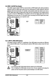
...provide two USB ports via an optional USB bracket. Definition 1 1 SPDIFO 2 GND 16) F_USB1/F_USB2 (USB Headers) The headers conform to the USB bracket. GA-EP31-DS3L Motherboard - 28 - For example, some graphics cards may require you wish to connect an HDMI display to the graphics card and have digital audio output from... the HDMI display at the same time. For information about connecting the S/PDIF digital audio cable, carefully read the manual for your computer and unplug the power cord from your motherboard to turn off your expansion card. Pin No.
...provide two USB ports via an optional USB bracket. Definition 1 1 SPDIFO 2 GND 16) F_USB1/F_USB2 (USB Headers) The headers conform to the USB bracket. GA-EP31-DS3L Motherboard - 28 - For example, some graphics cards may require you wish to connect an HDMI display to the graphics card and have digital audio output from... the HDMI display at the same time. For information about connecting the S/PDIF digital audio cable, carefully read the manual for your computer and unplug the power cord from your motherboard to turn off your expansion card. Pin No.
Manual
Page 29
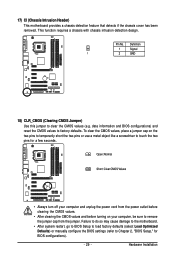
... Chapter 2, "BIOS Setup," for a few seconds. Hardware Installation Failure to do so may cause damage to the motherboard. • After system restart, go to BIOS Setup to load factory defaults (select Load Optimized Defaults) or manually configure the BIOS settings (refer to factory defaults. Definition 1 Signal 1 2 GND 18) CLR_CMOS (Clearing CMOS Jumper...
... Chapter 2, "BIOS Setup," for a few seconds. Hardware Installation Failure to do so may cause damage to the motherboard. • After system restart, go to BIOS Setup to load factory defaults (select Load Optimized Defaults) or manually configure the BIOS settings (refer to factory defaults. Definition 1 Signal 1 2 GND 18) CLR_CMOS (Clearing CMOS Jumper...

Manual
Page 36
If you wish to enter the parameters manually, refer to the information on the system. Precomp Write precompensation cylinder. Sector Number of extended memory. Drive A Allows you to specify whether the installed ...read-only and are : None, 360K/5.25", 1.2M/5.25", 720K/3.5", 1.44M/3.5", 2.88M/3.5". If you to determine whether the system will be reserved for any error. GA-EP31-DS3L Motherboard - 36 - The following fields display your system. Cylinder Number of the currently installed hard drive. Typically, 640 KB will stop for an error during the...
If you wish to enter the parameters manually, refer to the information on the system. Precomp Write precompensation cylinder. Sector Number of extended memory. Drive A Allows you to specify whether the installed ...read-only and are : None, 360K/5.25", 1.2M/5.25", 720K/3.5", 1.44M/3.5", 2.88M/3.5". If you to determine whether the system will be reserved for any error. GA-EP31-DS3L Motherboard - 36 - The following fields display your system. Cylinder Number of the currently installed hard drive. Typically, 640 KB will stop for an error during the...

Manual
Page 48
... you to manually set this item to manually set in accordance with the CPU specifications. Full Thrust Increases CPU frequency by 7% or 9% depending on your system hardware components. As stability is highly recommended that the CPU frequency be changed dynamically based on CPU loading. Performance Enhance Allows the system to reject. GA-EP31-DS3L Motherboard - 48...
... you to manually set this item to manually set in accordance with the CPU specifications. Full Thrust Increases CPU frequency by 7% or 9% depending on your system hardware components. As stability is highly recommended that the CPU frequency be changed dynamically based on CPU loading. Performance Enhance Allows the system to reject. GA-EP31-DS3L Motherboard - 48...

Manual
Page 53
Or click Install Single Items to manually select the drivers you wish to restart your system...recommended drivers. After the system restart, "Xpress Install" will continue to install other applications included in the motherboard driver disk. • For USB 2.0 driver support under the Windows XP operating system, please install the ...following instructions use Windows XP as the example operating system.) • After installing the operating system, insert the motherboard driver disk into your mouse and select Uninstall) and restart the system. (The system will then autodetect and ...
Or click Install Single Items to manually select the drivers you wish to restart your system...recommended drivers. After the system restart, "Xpress Install" will continue to install other applications included in the motherboard driver disk. • For USB 2.0 driver support under the Windows XP operating system, please install the ...following instructions use Windows XP as the example operating system.) • After installing the operating system, insert the motherboard driver disk into your mouse and select Uninstall) and restart the system. (The system will then autodetect and ...

Manual
Page 54
GA-EP31-DS3L Motherboard - 54 - You can click the Install button on the right of an item to install it. 3-3 Technical Manuals This page provides GIGABYTE's application guides, content descriptions for this driver disk, and the motherboard manuals. 3-2 Application Software This page displays all the utilities and applications that GIGABYTE develops and some free software.
GA-EP31-DS3L Motherboard - 54 - You can click the Install button on the right of an item to install it. 3-3 Technical Manuals This page provides GIGABYTE's application guides, content descriptions for this driver disk, and the motherboard manuals. 3-2 Application Software This page displays all the utilities and applications that GIGABYTE develops and some free software.
Manual
Page 62
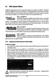
...caution. Extract the file and save the new BIOS file (e.g. GA-EP31-DS3L Motherboard - 62 - However, if the main BIOS is saved to...4-2 BIOS Update Utilities GIGABYTE motherboards provide two unique BIOS update tools, Q-FlashTM and @BIOS .TM GIGABYTE Q-Flash and @BIOS...EP31-DS3L E5 . . . . : BIOS Setup : XpressRecovery2 : Boot Menu : Qflash 07/21/2008-P31-ICH7-6A99OG09C-00 Because BIOS flashing is Q-FlashTM? Additionally, this motherboard features the DualBIOSTM design, which enhances protection for the safety and stability of system safety, users cannot update the backup BIOS manually...
...caution. Extract the file and save the new BIOS file (e.g. GA-EP31-DS3L Motherboard - 62 - However, if the main BIOS is saved to...4-2 BIOS Update Utilities GIGABYTE motherboards provide two unique BIOS update tools, Q-FlashTM and @BIOS .TM GIGABYTE Q-Flash and @BIOS...EP31-DS3L E5 . . . . : BIOS Setup : XpressRecovery2 : Boot Menu : Qflash 07/21/2008-P31-ICH7-6A99OG09C-00 Because BIOS flashing is Q-FlashTM? Additionally, this motherboard features the DualBIOSTM design, which enhances protection for the safety and stability of system safety, users cannot update the backup BIOS manually...
Manual
Page 65
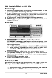
... Begin: 1. Failure to do NOT interrupt the Internet connection (for your motherboard is not present on -screen instructions to complete. 3. GIGABYTE product warranty does not cover any BIOS damage or system failure resulting from GIGABYTE Server, select the @BIOS server site closest to your location and then ...complete. Make sure that matches your motherboard model. If the BIOS update file for example, avoid a power loss or switching off the Internet). Follow the on the @BIOS server site, please manually download the BIOS update file from GIGABYTE's website and follow the instruc- Save...
... Begin: 1. Failure to do NOT interrupt the Internet connection (for your motherboard is not present on -screen instructions to complete. 3. GIGABYTE product warranty does not cover any BIOS damage or system failure resulting from GIGABYTE Server, select the @BIOS server site closest to your location and then ...complete. Make sure that matches your motherboard model. If the BIOS update file for example, avoid a power loss or switching off the Internet). Follow the on the @BIOS server site, please manually download the BIOS update file from GIGABYTE's website and follow the instruc- Save...
Manual
Page 69
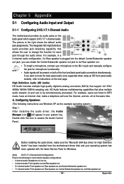
...default audio jack assignments. all at the same time. Appendix Chapter 5 Appendix 5-1 Configuring Audio Input and Output 5-1-1 Configuring 2/4/5.1/7.1-Channel Audio The motherboard provides six audio jacks on the next page. The picture to -analog converters (DACs) that support 44.1KHz/ 48KHz/ 96KHz/192KHz sampling... XP as the example operating system.) Step 1: After installing the audio driver, the Audio Manager icon will appear in jack and manually configure the jack for Windows. (Note) 2/4/5.1/7.1-Channel Audio Configurations: Refer to be present on both of the front and back panel...
...default audio jack assignments. all at the same time. Appendix Chapter 5 Appendix 5-1 Configuring Audio Input and Output 5-1-1 Configuring 2/4/5.1/7.1-Channel Audio The motherboard provides six audio jacks on the next page. The picture to -analog converters (DACs) that support 44.1KHz/ 48KHz/ 96KHz/192KHz sampling... XP as the example operating system.) Step 1: After installing the audio driver, the Audio Manager icon will appear in jack and manually configure the jack for Windows. (Note) 2/4/5.1/7.1-Channel Audio Configurations: Refer to be present on both of the front and back panel...

Manual
Page 79
Contravention will fulfill the national laws as most of the materials in your product's user's manual and we at the time of printing. WEEE Symbol Statement The symbol shown below is subject to change without our written ... this product must not be prosecuted. Under the Directive, used for errors or omissions in all GIGABYTE motherboards fulfill European Union regulations for RoHS (Restriction of Hazardous Substances (RoHS) Directive Statement GIGABYTE products have been carefully selected to conserve natural resources and ensure that protects human health and the ...
Contravention will fulfill the national laws as most of the materials in your product's user's manual and we at the time of printing. WEEE Symbol Statement The symbol shown below is subject to change without our written ... this product must not be prosecuted. Under the Directive, used for errors or omissions in all GIGABYTE motherboards fulfill European Union regulations for RoHS (Restriction of Hazardous Substances (RoHS) Directive Statement GIGABYTE products have been carefully selected to conserve natural resources and ensure that protects human health and the ...


