Manual
Page 3
... read or download the information on/from the Support&Downloads\Motherboard\Technology Guide page on your motherboard revision before updating motherboard BIOS, drivers, or when looking for technical information. Check your motherboard looks like this manual are legally registered to their respective owners. Documentation Classifications In order to assist in the use GIGABYTE's unique features, read the User's Manual. For instructions on how to the specifications and features...
... read or download the information on/from the Support&Downloads\Motherboard\Technology Guide page on your motherboard revision before updating motherboard BIOS, drivers, or when looking for technical information. Check your motherboard looks like this manual are legally registered to their respective owners. Documentation Classifications In order to assist in the use GIGABYTE's unique features, read the User's Manual. For instructions on how to the specifications and features...
Manual
Page 4
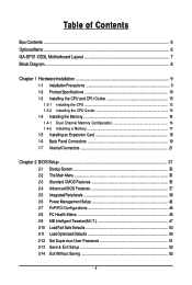
......6 GA-EP31-DS3L Motherboard Layout 7 Block Diagram...8 Chapter 1 Hardware Installation 9 1-1 Installation Precautions 9 1-2 Product Specifications 10 1-3 Installing the CPU and CPU Cooler 13 1-3-1 Installing the CPU 13 1-3-2 Installing the CPU Cooler 15 1-4 Installing the Memory 16 1-4-1 Dual Channel Memory Configuration 16 1-4-2 Installing a Memory 17 1-5 Installing an Expansion Card 18 1-6 Back Panel Connectors 19 1-7 Internal Connectors 21 Chapter 2 BIOS Setup 31 2-1 Startup Screen 32 2-2 The Main Menu 33 2-3 Standard CMOS Features 35 2-4 Advanced BIOS Features...
......6 GA-EP31-DS3L Motherboard Layout 7 Block Diagram...8 Chapter 1 Hardware Installation 9 1-1 Installation Precautions 9 1-2 Product Specifications 10 1-3 Installing the CPU and CPU Cooler 13 1-3-1 Installing the CPU 13 1-3-2 Installing the CPU Cooler 15 1-4 Installing the Memory 16 1-4-1 Dual Channel Memory Configuration 16 1-4-2 Installing a Memory 17 1-5 Installing an Expansion Card 18 1-6 Back Panel Connectors 19 1-7 Internal Connectors 21 Chapter 2 BIOS Setup 31 2-1 Startup Screen 32 2-2 The Main Menu 33 2-3 Standard CMOS Features 35 2-4 Advanced BIOS Features...
Manual
Page 16
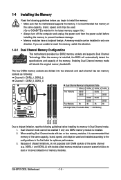
... memory modules to prevent system's failure to GIGABYTE's website for optimum performance. 3. Enabling Dual Channel memory mode will automatically detect the specifications and capacity of memory modules. DS/SS DS/SS - - - - GA-EP31-DS3L Motherboard - 16 - DS/SS - - DS/SS - - Because of chipset limitations, do not populate both DIMM sockets of the same capacity, brand, speed, and chips be used . (Go to start or incorrect detection of the memory. Dual Channel mode cannot be installed...
... memory modules to prevent system's failure to GIGABYTE's website for optimum performance. 3. Enabling Dual Channel memory mode will automatically detect the specifications and capacity of memory modules. DS/SS DS/SS - - - - GA-EP31-DS3L Motherboard - 16 - DS/SS - - DS/SS - - Because of chipset limitations, do not populate both DIMM sockets of the same capacity, brand, speed, and chips be used . (Go to start or incorrect detection of the memory. Dual Channel mode cannot be installed...
Manual
Page 18
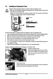
... damage. Turn on the card are completely inserted into the PCI Express x16 slot. Locate an expansion slot that came with the expansion card in your expansion card. • Always turn off the computer and unplug the power cord from the chassis back panel. 2. Example: Installing and Removing a PCI Express x16 Graphics Card: • Installing a Graphics Card: Gently insert the graphics card into the slot. 4. GA-EP31-DS3L Motherboard - 18 - Carefully read the manual that supports your expansion card in the slot. 3. Make...
... damage. Turn on the card are completely inserted into the PCI Express x16 slot. Locate an expansion slot that came with the expansion card in your expansion card. • Always turn off the computer and unplug the power cord from the chassis back panel. 2. Example: Installing and Removing a PCI Express x16 Graphics Card: • Installing a Graphics Card: Gently insert the graphics card into the slot. 4. GA-EP31-DS3L Motherboard - 18 - Carefully read the manual that supports your expansion card in the slot. 3. Make...
Manual
Page 25
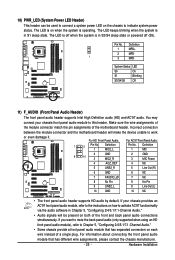
... the device unable to work or even damage it. Definition 1 MPD+ 2 MPD- 1 3 MPD- Incorrect connection between the module connector and the motherboard header will be used to connect a system power LED on the chassis to activate AC'97 functioninality via the audio software in S1 sleep state. System Status LED S0 On S1 Blinking S3/S4/S5 Off 11) F_AUDIO (Front Panel Audio Header) The front panel audio header supports Intel High Definition audio...
... the device unable to work or even damage it. Definition 1 MPD+ 2 MPD- 1 3 MPD- Incorrect connection between the module connector and the motherboard header will be used to connect a system power LED on the chassis to activate AC'97 functioninality via the audio software in S1 sleep state. System Status LED S0 On S1 Blinking S3/S4/S5 Off 11) F_AUDIO (Front Panel Audio Header) The front panel audio header supports Intel High Definition audio...
Manual
Page 29
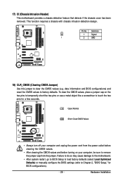
... reset the CMOS values to clear the CMOS values (e.g. Open: Normal Short: Clear CMOS Values • Always turn off your computer, be sure to Chapter 2, "BIOS Setup," for a few seconds. Hardware Installation Definition 1 Signal 1 2 GND 18) CLR_CMOS (Clearing CMOS Jumper) Use this jumper to factory defaults. Pin No. Failure to do so may cause damage to the motherboard. • After system restart, go to BIOS Setup to load factory defaults (select Load Optimized Defaults) or manually configure the BIOS settings...
... reset the CMOS values to clear the CMOS values (e.g. Open: Normal Short: Clear CMOS Values • Always turn off your computer, be sure to Chapter 2, "BIOS Setup," for a few seconds. Hardware Installation Definition 1 Signal 1 2 GND 18) CLR_CMOS (Clearing CMOS Jumper) Use this jumper to factory defaults. Pin No. Failure to do so may cause damage to the motherboard. • After system restart, go to BIOS Setup to load factory defaults (select Load Optimized Defaults) or manually configure the BIOS settings...
Manual
Page 32
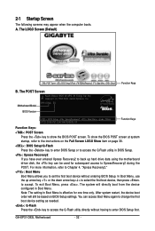
A. The LOGO Screen (Default) :POST Screen :BIOS Setup/Q-Flash :XpressRecovery2 :Boot Menu :Qflash Function Keys B. In Boot Menu, use the up hard drive data using the motherboard driver disk, the key can access Boot Menu again to change the first boot device setting as needed. : Q-Flash Press the key to access the Q-Flash utility directly without entering BIOS Setup. GA-EP31-DS3L Motherboard - 32 - Note: The setting in Boot Menu. 2-1 Startup Screen The following screens may appear when the computer boots. The POST Screen Award Modular BIOS v6.00PG, An Energy Star Ally ...
A. The LOGO Screen (Default) :POST Screen :BIOS Setup/Q-Flash :XpressRecovery2 :Boot Menu :Qflash Function Keys B. In Boot Menu, use the up hard drive data using the motherboard driver disk, the key can access Boot Menu again to change the first boot device setting as needed. : Q-Flash Press the key to access the Q-Flash utility directly without entering BIOS Setup. GA-EP31-DS3L Motherboard - 32 - Note: The setting in Boot Menu. 2-1 Startup Screen The following screens may appear when the computer boots. The POST Screen Award Modular BIOS v6.00PG, An Energy Star Ally ...
Manual
Page 34
..., hard drive types, floppy disk drive types, and the type of errors that stop the system boot, etc. „ Advanced BIOS Features Use this menu to configure the device boot order, advanced features available on the CPU, and the primary display adapter. „ Integrated Peripherals Use this menu to configure all peripheral devices, such as IDE, SATA, USB, integrated audio, and integrated LAN, etc. „ Power Management Setup Use this menu to configure all the power-saving functions. „ PnP/PCI Configurations Use this menu to configure the...
..., hard drive types, floppy disk drive types, and the type of errors that stop the system boot, etc. „ Advanced BIOS Features Use this menu to configure the device boot order, advanced features available on the CPU, and the primary display adapter. „ Integrated Peripherals Use this menu to configure all peripheral devices, such as IDE, SATA, USB, integrated audio, and integrated LAN, etc. „ Power Management Setup Use this menu to configure all the power-saving functions. „ PnP/PCI Configurations Use this menu to configure the...
Manual
Page 35
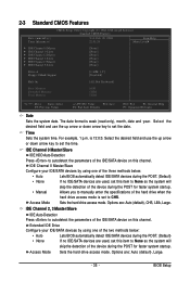
...; Manual Lets BIOS automatically detect IDE/SATA devices during the POST. (Default) If no IDE/SATA devices are used , set the date. Access Mode Sets the hard drive access mode. BIOS Setup Select the desired field and use the up arrow or down arrow key to CHS. Options are : Auto (default), Large. - 35 - IDE Channel 0 Master/Slave IDE HDD Auto-Detection Press to autodetect the parameters of the hard drive when the hard drive access mode is set to set this channel. For example, 1 p.m. IDE Channel 0 Master/Slave Configure your IDE/SATA devices by using one...
...; Manual Lets BIOS automatically detect IDE/SATA devices during the POST. (Default) If no IDE/SATA devices are used , set the date. Access Mode Sets the hard drive access mode. BIOS Setup Select the desired field and use the up arrow or down arrow key to CHS. Options are : Auto (default), Large. - 35 - IDE Channel 0 Master/Slave IDE HDD Auto-Detection Press to autodetect the parameters of the hard drive when the hard drive access mode is set to set this channel. For example, 1 p.m. IDE Channel 0 Master/Slave Configure your IDE/SATA devices by using one...
Manual
Page 37
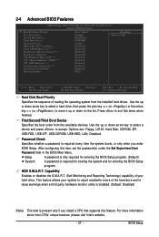
... entering the BIOS Setup program. (Default) A password is required every time the system boots, or only when you install a CPU that supports this menu when finished. 2-4 Advanced BIOS Features CMOS Setup Utility-Copyright (C) 1984-2008 Award Software Advanced BIOS Features ` Hard Disk Boot Priority First Boot Device Second Boot Device Third Boot Device Password Check HDD S.M.A.R.T. HDD S.M.A.R.T. After configuring this item, set the password(s) under the Set Supervisor/User Password item in the BIOS Main Menu. Use the up or down arrow key to select a hard drive, then press the plus key...
... entering the BIOS Setup program. (Default) A password is required every time the system boots, or only when you install a CPU that supports this menu when finished. 2-4 Advanced BIOS Features CMOS Setup Utility-Copyright (C) 1984-2008 Award Software Advanced BIOS Features ` Hard Disk Boot Priority First Boot Device Second Boot Device Third Boot Device Password Check HDD S.M.A.R.T. HDD S.M.A.R.T. After configuring this item, set the password(s) under the Set Supervisor/User Password item in the BIOS Main Menu. Use the up or down arrow key to select a hard drive, then press the plus key...
Manual
Page 38
.... GA-EP31-DS3L Motherboard - 38 - Set this feature. When enabled, the CPU core frequency and voltage will be reduced when the CPU is present only if you to determine whether to Disabled for legacy operating system such as multiple virtual systems. (Default: Enabled) Full Screen LOGO Show Allows you to determine whether to display the GIGABYTE Logo at system startup. PCI Sets the PCI graphics card as the first display. (Default) PEG Sets the PCI Express graphics card as the first display...
.... GA-EP31-DS3L Motherboard - 38 - Set this feature. When enabled, the CPU core frequency and voltage will be reduced when the CPU is present only if you to determine whether to Disabled for legacy operating system such as multiple virtual systems. (Default: Enabled) Full Screen LOGO Show Allows you to determine whether to display the GIGABYTE Logo at system startup. PCI Sets the PCI graphics card as the first display. (Default) PEG Sets the PCI Express graphics card as the first display...
Manual
Page 39
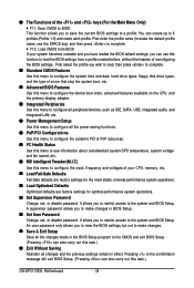
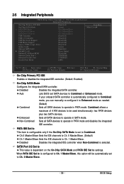
...Utility-Copyright (C) 1984-2008 Award Software Integrated Peripherals On-Chip Primary PCI IDE On-Chip SATA Mode x PATA IDE Set to SATA Port 0/2 Set to SATA Port 1/3 Set to Ch. 1 Master/Slave. If your onboard SATA controller is selected. Enhanced Sets all SATA devices to operate in SATA mode. Ch.0 Master/Slave Sets the IDE channels to Ch. 0 Master/Slave. (Default) Ch.1 Master/Slave Sets the IDE channels to USB Controller USB 2.0 Controller USB Keyboard Support USB Mouse Support Legacy USB storage detect Azalia Codec Onboard H/W LAN ` SMART LAN Onboard LAN Boot ROM Onboard Serial Port...
...Utility-Copyright (C) 1984-2008 Award Software Integrated Peripherals On-Chip Primary PCI IDE On-Chip SATA Mode x PATA IDE Set to SATA Port 0/2 Set to SATA Port 1/3 Set to Ch. 1 Master/Slave. If your onboard SATA controller is selected. Enhanced Sets all SATA devices to operate in SATA mode. Ch.0 Master/Slave Sets the IDE channels to Ch. 0 Master/Slave. (Default) Ch.1 Master/Slave Sets the IDE channels to USB Controller USB 2.0 Controller USB Keyboard Support USB Mouse Support Legacy USB storage detect Azalia Codec Onboard H/W LAN ` SMART LAN Onboard LAN Boot ROM Onboard Serial Port...
Manual
Page 40
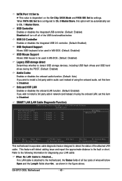
... install a 3rd party add-in MS-DOS. (Default: Disabled) USB Mouse Support Allows USB mouse to be automatically set this option will turn off all four pairs of the attached LAN cable. GA-EP31-DS3L Motherboard - 40 - When PATA IDE Set to is configured to Ch. 0 Master/Slave, this item to the following information for diagnosing your LAN cable: When No LAN Cable Is Attached... SMART LAN (LAN Cable Diagnostic Function) CMOS Setup Utility-Copyright (C) 1984-2008 Award Software SMART LAN Start detecting at Port...
... install a 3rd party add-in MS-DOS. (Default: Disabled) USB Mouse Support Allows USB mouse to be automatically set this option will turn off all four pairs of the attached LAN cable. GA-EP31-DS3L Motherboard - 40 - When PATA IDE Set to is configured to Ch. 0 Master/Slave, this item to the following information for diagnosing your LAN cable: When No LAN Cable Is Attached... SMART LAN (LAN Cable Diagnostic Function) CMOS Setup Utility-Copyright (C) 1984-2008 Award Software SMART LAN Start detecting at Port...
Manual
Page 41
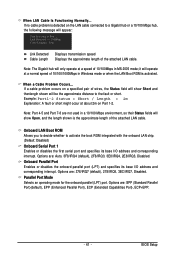
... mode; If a cable problem occurs on the LAN cable connected to a Gigabit hub or a 10/100 Mbps hub, the following message will operate at Port..... it will appear: Start detecting at a normal speed of 10/100Mbps in a 10/100 Mbps environment, so their Status fields will be the approximate distance to activate the boot ROM integrated with the onboard LAN chip. (Default: Disabled) Onboard Serial Port 1 Enables or disables the first serial port...
... mode; If a cable problem occurs on the LAN cable connected to a Gigabit hub or a 10/100 Mbps hub, the following message will operate at Port..... it will appear: Start detecting at a normal speed of 10/100Mbps in a 10/100 Mbps environment, so their Status fields will be the approximate distance to activate the boot ROM integrated with the onboard LAN chip. (Default: Disabled) Onboard Serial Port 1 Enables or disables the first serial port...
Manual
Page 45
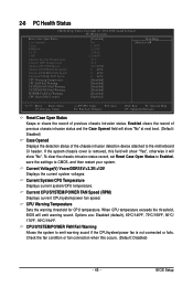
... chassis intrusion status. When CPU temperature exceeds the threshold, BIOS will show "No". BIOS Setup To clear the chassis intrusion status record, set Reset Case Open Status to Enabled, save the settings to emit warning sound if the CPU/system/power fan is removed, this occurs. (Default: Disabled) - 45 - Current Voltage(V) Vcore/DDR18V/+3.3V/+12V Displays the current system voltages. Current CPU/SYSTEM/POWER FAN Speed (RPM) Displays current CPU/system/power fan speed. CPU Warning Temperature Sets the warning threshold for CPU temperature. Options are: Disabled (default...
... chassis intrusion status. When CPU temperature exceeds the threshold, BIOS will show "No". BIOS Setup To clear the chassis intrusion status record, set Reset Case Open Status to Enabled, save the settings to emit warning sound if the CPU/system/power fan is removed, this occurs. (Default: Disabled) - 45 - Current Voltage(V) Vcore/DDR18V/+3.3V/+12V Displays the current system voltages. Current CPU/SYSTEM/POWER FAN Speed (RPM) Displays current CPU/system/power fan speed. CPU Warning Temperature Sets the warning threshold for CPU temperature. Options are: Disabled (default...
Manual
Page 47
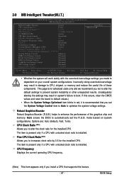
...'s failure to CPU, chipset, or memory and reduce the useful life of the graphics chip and memory. Options are: Auto (default), Fast, Turbo. Incorrectly doing overclock/overvoltage may result in damage to boot. If this feature. - 47 - The item is present only if a CPU with unlocked clock ratio is installed. The item is present only if a CPU with unlocked clock ratio is installed. 2-9 MB Intelligent Tweaker(M.I.T.) CMOS Setup Utility-Copyright (C) 1984-2008 Award Software...
...'s failure to CPU, chipset, or memory and reduce the useful life of the graphics chip and memory. Options are: Auto (default), Fast, Turbo. Incorrectly doing overclock/overvoltage may result in damage to boot. If this feature. - 47 - The item is present only if a CPU with unlocked clock ratio is installed. The item is present only if a CPU with unlocked clock ratio is installed. 2-9 MB Intelligent Tweaker(M.I.T.) CMOS Setup Utility-Copyright (C) 1984-2008 Award Software...
Manual
Page 52
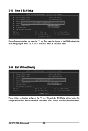
... & Exit Setup F11: Save CMOS to BIOS F12: Load CMOS from BIOS Save Data to CMOS Press on this item and press the key. Press or to return to the BIOS Setup Main Menu. 2-14 Exit Without Saving CMOS Setup Utility-Copyright (C) 1984-2008 Award Software ` Standard CMOS Features Load Fail-Safe Defaults ` Advanced BIOS Features Load Optimized Defaults ` Integrated Peripherals Set Supervisor Password ` Power Management Setup Quit Without Saving (SYe/tNU)?seNr Password ` PnP/PCI Configurations Save & Exit Setup ` PC Health...
... & Exit Setup F11: Save CMOS to BIOS F12: Load CMOS from BIOS Save Data to CMOS Press on this item and press the key. Press or to return to the BIOS Setup Main Menu. 2-14 Exit Without Saving CMOS Setup Utility-Copyright (C) 1984-2008 Award Software ` Standard CMOS Features Load Fail-Safe Defaults ` Advanced BIOS Features Load Optimized Defaults ` Integrated Peripherals Set Supervisor Password ` Power Management Setup Quit Without Saving (SYe/tNU)?seNr Password ` PnP/PCI Configurations Save & Exit Setup ` PC Health...
Manual
Page 62
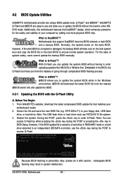
..., if the main BIOS is saved to a hard drive in RAID/AHCI mode or a hard drive attached to an independent IDE/SATA controller, use the key during the POST or pressing the key in the Windows environment. @BIOS will take over on the main BIOS. 4-2 BIOS Update Utilities GIGABYTE motherboards provide two unique BIOS update tools, Q-FlashTM and @BIOS .TM GIGABYTE Q-Flash and @BIOS are easy-to-use and allow you to update the BIOS without having to enter Q-Flash. Before You Begin: 1. EP31-DS3L E5 . . . . : BIOS Setup : XpressRecovery2 : Boot Menu : Qflash...
..., if the main BIOS is saved to a hard drive in RAID/AHCI mode or a hard drive attached to an independent IDE/SATA controller, use the key during the POST or pressing the key in the Windows environment. @BIOS will take over on the main BIOS. 4-2 BIOS Update Utilities GIGABYTE motherboards provide two unique BIOS update tools, Q-FlashTM and @BIOS .TM GIGABYTE Q-Flash and @BIOS are easy-to-use and allow you to update the BIOS without having to enter Q-Flash. Before You Begin: 1. EP31-DS3L E5 . . . . : BIOS Setup : XpressRecovery2 : Boot Menu : Qflash...
Manual
Page 63
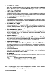
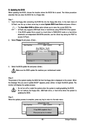
... of Q-Flash, use the key during the POST to a floppy disk. appears, press to update BIOS?" Q-Flash Utility v2.05 Flash Type/Size MXIC 25L8005 1M EnteFr l:oRppuyn A HDD 0-0 Keep DMI Data Enable Update BIOS from Drive and press . • The Save Main BIOS to Drive option allows you save the current BIOS file. • Q-Flash only supports USB flash drive or hard drives using FAT32/16/12 file system. • If the BIOS update file is saved to a hard drive in RAID/AHCI mode or a hard drive attached to an independent IDE/SATA controller, use the...
... of Q-Flash, use the key during the POST to a floppy disk. appears, press to update BIOS?" Q-Flash Utility v2.05 Flash Type/Size MXIC 25L8005 1M EnteFr l:oRppuyn A HDD 0-0 Keep DMI Data Enable Update BIOS from Drive and press . • The Save Main BIOS to Drive option allows you save the current BIOS file. • Q-Flash only supports USB flash drive or hard drives using FAT32/16/12 file system. • If the BIOS update file is saved to a hard drive in RAID/AHCI mode or a hard drive attached to an independent IDE/SATA controller, use the...

Manual
Page 76
... like a screwdriver to clear the CMOS values. Q:Why do I still get a weak sound even though I clear the CMOS values? A: The following Award BIOS beep code descriptions may help you identify possible computer problems. (For reference only.) 1 short: System boots successfully 2 short: CMOS setting error 1 long, 1 short: Memory or motherboard error 1 long, 2 short: Monitor or graphics card error 1 long, 3 short: Keyboard error 1 long, 9 short: BIOS ROM error Continuous long beeps: Graphics card not inserted properly Continuous short beeps: Power error GA-EP31-DS3L Motherboard - 76 -
... like a screwdriver to clear the CMOS values. Q:Why do I still get a weak sound even though I clear the CMOS values? A: The following Award BIOS beep code descriptions may help you identify possible computer problems. (For reference only.) 1 short: System boots successfully 2 short: CMOS setting error 1 long, 1 short: Memory or motherboard error 1 long, 2 short: Monitor or graphics card error 1 long, 3 short: Keyboard error 1 long, 9 short: BIOS ROM error Continuous long beeps: Graphics card not inserted properly Continuous short beeps: Power error GA-EP31-DS3L Motherboard - 76 -


