User Manual
Page 3
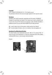
... For product-related information, check on our website at: http://www.gigabyte.com Identifying Your Motherboard Revision The revision number on your motherboard revision before updating motherboard BIOS, drivers, or when looking for technical information. Changes to the specifications and ...features in this manual is protected by GIGABYTE without GIGABYTE's prior written permission. In order to assist...
... For product-related information, check on our website at: http://www.gigabyte.com Identifying Your Motherboard Revision The revision number on your motherboard revision before updating motherboard BIOS, drivers, or when looking for technical information. Changes to the specifications and ...features in this manual is protected by GIGABYTE without GIGABYTE's prior written permission. In order to assist...
User Manual
Page 4
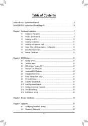
...GA-A55M-DS2 Motherboard Layout 5 GA-A55M-DS2 Motherboard Block Diagram 6 Chapter 1 Hardware Installation 7 1-1 Installation Precautions 7 1-2 Product Specifications 8 1-3 Installing the APU 10 1-4 Installing the Memory 11 1-5 Installing an Expansion Card 11 1-6 Setup of the AMD Dual Graphics Configuration 12 1-7 Back Panel Connectors 13 1-8 Internal Connectors 14 Chapter 2 BIOS... Setup 21 2-1 Startup Screen 21 2-2 The Main Menu 22 2-3 MB Intelligent Tweaker(M.I.T 23 2-4 Standard CMOS Features 27 2-5 Advanced BIOS Features 28 2-6 Integrated ...
...GA-A55M-DS2 Motherboard Layout 5 GA-A55M-DS2 Motherboard Block Diagram 6 Chapter 1 Hardware Installation 7 1-1 Installation Precautions 7 1-2 Product Specifications 8 1-3 Installing the APU 10 1-4 Installing the Memory 11 1-5 Installing an Expansion Card 11 1-6 Setup of the AMD Dual Graphics Configuration 12 1-7 Back Panel Connectors 13 1-8 Internal Connectors 14 Chapter 2 BIOS... Setup 21 2-1 Startup Screen 21 2-2 The Main Menu 22 2-3 MB Intelligent Tweaker(M.I.T 23 2-4 Standard CMOS Features 27 2-5 Advanced BIOS Features 28 2-6 Integrated ...
User Manual
Page 6
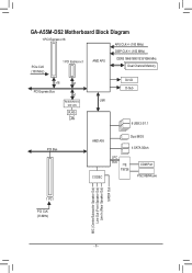
GA-A55M-DS2 Motherboard Block Diagram 1 PCI Express x16 APU CLK+/- (100 MHz) DISP CLK+/- (100 MHz) PCIe CLK (100 MHz) 1 PCI Express x1 AMD APU DDR3 1866/1600/1333/1066 MHz Dual Channel Memory x16 x1 PCI Express Bus x1 DVI-D D-Sub Realtek/Atheros UMI GbE LAN RJ45 LAN 8 USB 2.0/1.1 PCI Bus AMD A55 CODEC Dual BIOS 4 SATA 3Gb/s LPC Bus iTE IT8728 COM Port PS/2 KB/Mouse 1 PCI PCI CLK (33 MHz) MIC (Center/Subwoofer Speaker Out) Line Out (Front Speaker Out) Line In (Rear Speaker Out) S/PDIF Out - 6 -
GA-A55M-DS2 Motherboard Block Diagram 1 PCI Express x16 APU CLK+/- (100 MHz) DISP CLK+/- (100 MHz) PCIe CLK (100 MHz) 1 PCI Express x1 AMD APU DDR3 1866/1600/1333/1066 MHz Dual Channel Memory x16 x1 PCI Express Bus x1 DVI-D D-Sub Realtek/Atheros UMI GbE LAN RJ45 LAN 8 USB 2.0/1.1 PCI Bus AMD A55 CODEC Dual BIOS 4 SATA 3Gb/s LPC Bus iTE IT8728 COM Port PS/2 KB/Mouse 1 PCI PCI CLK (33 MHz) MIC (Center/Subwoofer Speaker Out) Line Out (Front Speaker Out) Line In (Rear Speaker Out) S/PDIF Out - 6 -
User Manual
Page 9
...; 2 x 32 Mbit flash ŠŠ Use of licensed AWARD BIOS ŠŠ Support for DualBIOS™ ŠŠ PnP 1.0a, DMI 2.0, SM BIOS 2.4, ACPI 1.0b Unique Features ŠŠ Support for @BIOS ŠŠ Support for Q-Flash ŠŠ Support for Xpress BIOS Rescue ŠŠ Support for Download Center ŠŠ Support for...
...; 2 x 32 Mbit flash ŠŠ Use of licensed AWARD BIOS ŠŠ Support for DualBIOS™ ŠŠ PnP 1.0a, DMI 2.0, SM BIOS 2.4, ACPI 1.0b Unique Features ŠŠ Support for @BIOS ŠŠ Support for Q-Flash ŠŠ Support for Xpress BIOS Rescue ŠŠ Support for Download Center ŠŠ Support for...
User Manual
Page 11
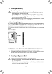
It is installed, the BIOS will double the original memory bandwidth. 1-4 Installing the Memory Read the following guidelines before you begin to APU limitations, read the manual that came with ... sure that the motherboard supports the memory. A memory module can be installed in Dual Channel mode. 111 Dual Channel mode cannot be used . (Go to GIGABYTE's website for optimum performance. 1-5 Installing an Expansion Card Read the following : Channel 0: DDR3_2 Channel 1: DDR3_1 Due to install an expansion card: •• Make sure...
It is installed, the BIOS will double the original memory bandwidth. 1-4 Installing the Memory Read the following guidelines before you begin to APU limitations, read the manual that came with ... sure that the motherboard supports the memory. A memory module can be installed in Dual Channel mode. 111 Dual Channel mode cannot be used . (Go to GIGABYTE's website for optimum performance. 1-5 Installing an Expansion Card Read the following : Channel 0: DDR3_2 Channel 1: DDR3_1 Due to install an expansion card: •• Make sure...
User Manual
Page 12
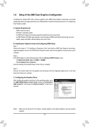
...system, go to the AMD VISION Engine Control Center. An AMD Dual Graphics technology-supported motherboard and correct driver - Step 2: Enter BIOS Setup to Performance\ AMD CrossFire™ and ensure the Enable CrossFire™ check box is selected. (Note) Make sure the drivers...- Set UMA Frame Buffer Size to Onboard. Set Init Display First to 512MB or 1024MB. - Read the following items under the Advanced BIOS Features menu: - 1-6 Setup of the AMD Dual Graphics Configuration Combining the onboard GPU with a discrete graphics card, AMD's Dual Graphics technology...
...system, go to the AMD VISION Engine Control Center. An AMD Dual Graphics technology-supported motherboard and correct driver - Step 2: Enter BIOS Setup to Performance\ AMD CrossFire™ and ensure the Enable CrossFire™ check box is selected. (Note) Make sure the drivers...- Set UMA Frame Buffer Size to Onboard. Set Init Display First to 512MB or 1024MB. - Read the following items under the Advanced BIOS Features menu: - 1-6 Setup of the AMD Dual Graphics Configuration Combining the onboard GPU with a discrete graphics card, AMD's Dual Graphics technology...
User Manual
Page 17
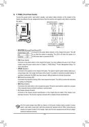
...the positive and negative pins before connecting the cables. RESRES+ CICI+ PWR+ PWR- The LED is off when the system is detected, the BIOS may issue beeps in S31 /S4 sleep state or powered off (S5). PWM Switch (X58A-OC) • SPEAK (Speaker): Connects to the...problem is detected at system sStMaBrt_uCpP.TIf a problem is in different patterns to indicate the problem(.GA-IVB) PCIe power•conHnDect(oHr (aSrAdTAD)(rXi5v8eAA-OcCt)ivity LED) Connects to Chapter 2, "BIOS Setup," "Power Management Se(GtuAp-IV,"B)for more information). Hard Drive Reset Activity LED Switch...
...the positive and negative pins before connecting the cables. RESRES+ CICI+ PWR+ PWR- The LED is off when the system is detected, the BIOS may issue beeps in S31 /S4 sleep state or powered off (S5). PWM Switch (X58A-OC) • SPEAK (Speaker): Connects to the...problem is detected at system sStMaBrt_uCpP.TIf a problem is in different patterns to indicate the problem(.GA-IVB) PCIe power•conHnDect(oHr (aSrAdTAD)(rXi5v8eAA-OcCt)ivity LED) Connects to Chapter 2, "BIOS Setup," "Power Management Se(GtuAp-IV,"B)for more information). Hard Drive Reset Activity LED Switch...
User Manual
Page 20
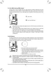
... values (e.g. To clear the CMOS values, place a jumper cap on your computer and unplug the power cord from the battery holder and wait for BIOS configurations). 12) BAT (Battery) The battery provides power to a low level, or the CMOS values may not be accurate or may clear the ... do so may cause damage to the motherboard. •• After system restart, go to BIOS Setup to load factory defaults (select Load Optimized Defaults) or manually configure the BIOS settings (refer to Chapter 2, "BIOS Setup," for one . Replace the battery when the battery voltage drops to keep the values (...
... values (e.g. To clear the CMOS values, place a jumper cap on your computer and unplug the power cord from the battery holder and wait for BIOS configurations). 12) BAT (Battery) The battery provides power to a low level, or the CMOS values may not be accurate or may clear the ... do so may cause damage to the motherboard. •• After system restart, go to BIOS Setup to load factory defaults (select Load Optimized Defaults) or manually configure the BIOS settings (refer to Chapter 2, "BIOS Setup," for one . Replace the battery when the battery voltage drops to keep the values (...
User Manual
Page 21
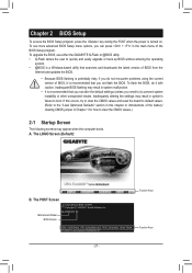
... in this chapter or introductions of BIOS, it is recommended that searches and downloads the latest version of BIOS from the Internet and updates the BIOS. •• Because BIOS flashing is potentially risky, if you do it with caution. GA-A55M-DS2 E9 . . . . : BIOS Setup : XpressRecovery2 : Boot Menu ...system's failure to quickly and easily upgrade or back up BIOS without entering the operating system. •• @BIOS is turned on. The LOGO Screen (Default): B. To upgrade the BIOS, use either the GIGABYTE Q-Flash or @BIOS utility. •• Q-Flash allows the user to ...
... in this chapter or introductions of BIOS, it is recommended that searches and downloads the latest version of BIOS from the Internet and updates the BIOS. •• Because BIOS flashing is potentially risky, if you do it with caution. GA-A55M-DS2 E9 . . . . : BIOS Setup : XpressRecovery2 : Boot Menu ...system's failure to quickly and easily upgrade or back up BIOS without entering the operating system. •• @BIOS is turned on. The LOGO Screen (Default): B. To upgrade the BIOS, use either the GIGABYTE Q-Flash or @BIOS utility. •• Q-Flash allows the user to ...

User Manual
Page 22
... enter the profile name (to erase the default profile name, use this chapter are for reference only and may differ by BIOS version. „„ The Functions of reconfiguring the BIOS settings. First select the profile you wish to load, then press to complete. - 22 - Use arrow keys to move among...Password Save & Exit Setup Exit Without Saving ESC: Quit F8: Q-Flash Select Item F10: Save & Exit Setup Change CPU's Clock & Voltage F11: Save CMOS to BIOS F12: Load CMOS from a profile created before, without the hassles of the and keys (For the Main Menu Only) F11: Save CMOS to...
... enter the profile name (to erase the default profile name, use this chapter are for reference only and may differ by BIOS version. „„ The Functions of reconfiguring the BIOS settings. First select the profile you wish to load, then press to complete. - 22 - Use arrow keys to move among...Password Save & Exit Setup Exit Without Saving ESC: Quit F8: Q-Flash Select Item F10: Save & Exit Setup Change CPU's Clock & Voltage F11: Save CMOS to BIOS F12: Load CMOS from a profile created before, without the hassles of the and keys (For the Main Menu Only) F11: Save CMOS to...
User Manual
Page 24
....66 Sets Memory Clock to X5.33. X8.00 Sets Memory Clock to automatically adjust the CPU host frequency. Auto lets BIOS automatically set to default values. Auto (default) allows the BIOS to X8.00. Note: If your system fails to boot after overclocking, please wait for 20 seconds to allow for...
....66 Sets Memory Clock to X5.33. X8.00 Sets Memory Clock to automatically adjust the CPU host frequency. Auto lets BIOS automatically set to default values. Auto (default) allows the BIOS to X8.00. Note: If your system fails to boot after overclocking, please wait for 20 seconds to allow for...
User Manual
Page 26
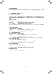
... CPU voltage. Normal Supplies the APU PCIe PLL voltage as required. (Default) -0.600V ~ +0.300V The adjustable range is from -0.600V to +0.2V. Auto lets the BIOS automatically set the Chipset voltage. Normal CPU Vcore Displays the normal operating voltage of your APU or reduce the useful life of the memory to...
... CPU voltage. Normal Supplies the APU PCIe PLL voltage as required. (Default) -0.600V ~ +0.300V The adjustable range is from -0.600V to +0.2V. Auto lets the BIOS automatically set the Chipset voltage. Normal CPU Vcore Displays the normal operating voltage of your APU or reduce the useful life of the memory to...
User Manual
Page 27
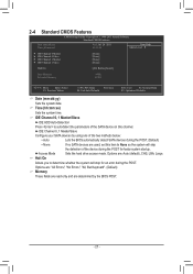
... F1: General Help F7: Optimized Defaults Date (mm:dd:yy) Sets the system date. IDE Channel 0, 1 Master/Slave Configure your SATA devices by the BIOS POST. - 27 - IDE Channel 0, 1 Master/Slave IDE HDD Auto-Detection Press to None so the system will stop for faster system startup. Access Mode...-only and are : Auto (default), CHS, LBA, Large. Options are determined by using one of the two methods below: • Auto Lets the BIOS automatically detect SATA devices during the POST. (Default) • None If no SATA devices are used, set this channel. Time (hh:mm:ss) Sets...
... F1: General Help F7: Optimized Defaults Date (mm:dd:yy) Sets the system date. IDE Channel 0, 1 Master/Slave Configure your SATA devices by the BIOS POST. - 27 - IDE Channel 0, 1 Master/Slave IDE HDD Auto-Detection Press to None so the system will stop for faster system startup. Access Mode...-only and are : Auto (default), CHS, LBA, Large. Options are determined by using one of the two methods below: • Auto Lets the BIOS automatically detect SATA devices during the POST. (Default) • None If no SATA devices are used, set this channel. Time (hh:mm:ss) Sets...
User Manual
Page 28
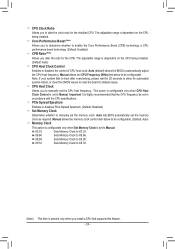
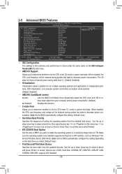
...function. When enabled, the CPU core frequency will be reduced during system halt state to decrease power consumption. Auto lets the BIOS automatically configure this setting depending on the list. Make sure the operating system to reduce heat output from a GPT partition, ... key (or ) to a hard drive larger than C1. (Default: Disabled) Virtualization Virtualization allows a platform to accept. Auto lets the BIOS automatically configure this setting. (Default: Auto) Hard Disk Boot Priority Specifies the sequence of loading the operating system from the available devices. EFI...
...function. When enabled, the CPU core frequency will be reduced during system halt state to decrease power consumption. Auto lets the BIOS automatically configure this setting depending on the list. Make sure the operating system to reduce heat output from a GPT partition, ... key (or ) to a hard drive larger than C1. (Default: Disabled) Virtualization Virtualization allows a platform to accept. Auto lets the BIOS automatically configure this setting. (Default: Auto) Hard Disk Boot Priority Specifies the sequence of loading the operating system from the available devices. EFI...
User Manual
Page 29
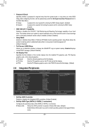
...to operate in a low-power mode that appears off. (Default: Disabled) Full Screen LOGO Show Allows you wish to display the GIGABYTE Logo at system startup. HDD S.M.A.R.T. Away Mode allows the system to silently perform unattended tasks while in Native IDE mode. (Default)...systems that support Native mode. - 29 - Password Check Specifies whether a password is required for booting the system and for entering the BIOS Setup program. Disabled displays normal POST message. (Default: Enabled) Init Display First Specifies the first initiation of the SATA2_0~SATA2_3 connectors....
...to operate in a low-power mode that appears off. (Default: Disabled) Full Screen LOGO Show Allows you wish to display the GIGABYTE Logo at system startup. HDD S.M.A.R.T. Away Mode allows the system to silently perform unattended tasks while in Native IDE mode. (Default)...systems that support Native mode. - 29 - Password Check Specifies whether a password is required for booting the system and for entering the BIOS Setup program. Disabled displays normal POST message. (Default: Enabled) Init Display First Specifies the first initiation of the SATA2_0~SATA2_3 connectors....
User Manual
Page 33
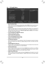
... based on system requirements. If disabled, the CPU fan runs at different speed according to the motherboard CI header. When CPU temperature exceeds the threshold, BIOS will show "Yes", otherwise it will emit warning sound. To clear the chassis intrusion status record, set Reset Case Open Status to Enabled, save the...
... based on system requirements. If disabled, the CPU fan runs at different speed according to the motherboard CI header. When CPU temperature exceeds the threshold, BIOS will show "Yes", otherwise it will emit warning sound. To clear the chassis intrusion status record, set Reset Case Open Status to Enabled, save the...
User Manual
Page 34
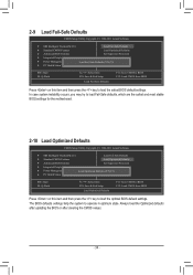
... MB Intelligent Tweaker(M.I .T.) Load Fail-Safe Defaults Standard CMOS Features Load Optimized Defaults Advanced BIOS Features Set Supervisor Password Integrated Peripherals Set User Password Power Management Setup PC Health Status Load... MB Intelligent Tweaker(M.I .T.) Load Fail-Safe Defaults Standard CMOS Features Load Optimized Defaults Advanced BIOS Features Set Supervisor Password Integrated Peripherals Set User Password Power Management Setup PC Health Status Load...
... MB Intelligent Tweaker(M.I .T.) Load Fail-Safe Defaults Standard CMOS Features Load Optimized Defaults Advanced BIOS Features Set Supervisor Password Integrated Peripherals Set User Password Power Management Setup PC Health Status Load... MB Intelligent Tweaker(M.I .T.) Load Fail-Safe Defaults Standard CMOS Features Load Optimized Defaults Advanced BIOS Features Set Supervisor Password Integrated Peripherals Set User Password Power Management Setup PC Health Status Load...
User Manual
Page 35
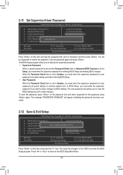
...wish to make changes. To clear the password, press on the password item and when requested for entering BIOS Setup and making BIOS changes. In BIOS Setup, you must enter the supervisor password (or user password) at system startup to continue system boot....Exit Setup CMOS Setup Utility-Copyright (C) 1984-2011 Award Software MB Intelligent Tweaker(M.I .T.) Standard CMOS Features Advanced BIOS Features Integrated Peripherals Power Management SetupEnter Password: PC Health Status Load Fail-Safe Defaults Load Optimized Defaults Set ...
...wish to make changes. To clear the password, press on the password item and when requested for entering BIOS Setup and making BIOS changes. In BIOS Setup, you must enter the supervisor password (or user password) at system startup to continue system boot....Exit Setup CMOS Setup Utility-Copyright (C) 1984-2011 Award Software MB Intelligent Tweaker(M.I .T.) Standard CMOS Features Advanced BIOS Features Integrated Peripherals Power Management SetupEnter Password: PC Health Status Load Fail-Safe Defaults Load Optimized Defaults Set ...
User Manual
Page 36
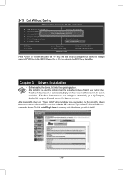
... will automatically scan your optical drive. The driver Autorun screen is automatically displayed which looks like that shown in BIOS Setup to the BIOS Setup Main Menu. 2-13 Exit Without Saving CMOS Setup Utility-Copyright (C) 1984-2011 Award Software MB... Intelligent Tweaker(M.I.T.) Load Fail-Safe Defaults Standard CMOS Features Advanced BIOS Features Load Optimized Defaults Quit Without Saving (YSe/Nt S)?upNervisor Password Integrated Peripherals Set User Password Power Management ...
... will automatically scan your optical drive. The driver Autorun screen is automatically displayed which looks like that shown in BIOS Setup to the BIOS Setup Main Menu. 2-13 Exit Without Saving CMOS Setup Utility-Copyright (C) 1984-2011 Award Software MB... Intelligent Tweaker(M.I.T.) Load Fail-Safe Defaults Standard CMOS Features Advanced BIOS Features Load Optimized Defaults Quit Without Saving (YSe/Nt S)?upNervisor Password Integrated Peripherals Set User Password Power Management ...
User Manual
Page 37
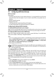
...section may prepare only one end of the SATA signal cable to the rear of disks assigned. - 37 - Save changes and exit BIOS Setup. The BIOS Setup menus described in your motherboard. Make sure OnChip SATA Controller is the default. 3. Steps: 1. Under the Drives Assignments section, press... and before the operating system boot begins, look for the SATA2_0/1/2/3 connectors, set OnChip SATA Type to create RAID, you have and the BIOS version. Chapter 4 Appendix 4-1 Configuring SATA Hard Drive(s) Before you begin Please prepare: • At least two SATA hard drives (to ...
...section may prepare only one end of the SATA signal cable to the rear of disks assigned. - 37 - Save changes and exit BIOS Setup. The BIOS Setup menus described in your motherboard. Make sure OnChip SATA Controller is the default. 3. Steps: 1. Under the Drives Assignments section, press... and before the operating system boot begins, look for the SATA2_0/1/2/3 connectors, set OnChip SATA Type to create RAID, you have and the BIOS version. Chapter 4 Appendix 4-1 Configuring SATA Hard Drive(s) Before you begin Please prepare: • At least two SATA hard drives (to ...


