Manual
Page 3
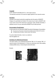
...Example: For product-related information, check on our website at: http://www.gigabyte.com Identifying Your Motherboard Revision The revision number on your motherboard revision before updating motherboard BIOS, drivers, or when looking for technical information. Disclaimer Information in this manual... are legally registered to assist in this manual is protected by GIGABYTE without GIGABYTE's prior written permission. No part of the...
...Example: For product-related information, check on our website at: http://www.gigabyte.com Identifying Your Motherboard Revision The revision number on your motherboard revision before updating motherboard BIOS, drivers, or when looking for technical information. Disclaimer Information in this manual... are legally registered to assist in this manual is protected by GIGABYTE without GIGABYTE's prior written permission. No part of the...
Manual
Page 4
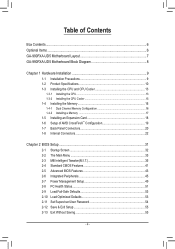
Table of Contents Box Contents...6 Optional Items...6 GA-990FXA-UD5 Motherboard Layout 7 GA-990FXA-UD5 Motherboard Block Diagram 8 Chapter 1 Hardware Installation 9 1-1 Installation Precautions 9 1-2 Product Specifications 10 1-3 Installing the CPU and CPU ...™ Configuration 19 1-7 Back Panel Connectors 20 1-8 Internal Connectors 22 Chapter 2 BIOS Setup 31 2-1 Startup Screen 32 2-2 The Main Menu 33 2-3 MB Intelligent Tweaker(M.I.T 35 2-4 Standard CMOS Features 41 2-5 Advanced BIOS Features 43 2-6 Integrated Peripherals 45 2-7 Power Management Setup 49 2-8 PC Health Status...
Table of Contents Box Contents...6 Optional Items...6 GA-990FXA-UD5 Motherboard Layout 7 GA-990FXA-UD5 Motherboard Block Diagram 8 Chapter 1 Hardware Installation 9 1-1 Installation Precautions 9 1-2 Product Specifications 10 1-3 Installing the CPU and CPU ...™ Configuration 19 1-7 Back Panel Connectors 20 1-8 Internal Connectors 22 Chapter 2 BIOS Setup 31 2-1 Startup Screen 32 2-2 The Main Menu 33 2-3 MB Intelligent Tweaker(M.I.T 35 2-4 Standard CMOS Features 41 2-5 Advanced BIOS Features 43 2-6 Integrated Peripherals 45 2-7 Power Management Setup 49 2-8 PC Health Status...
Manual
Page 5
... 58 3-4 Contact...59 3-5 System...59 3-6 Download Center 60 3-7 New Utilities...60 Chapter 4 Unique Features 61 4-1 Xpress Recovery2 61 4-2 BIOS Update Utilities 64 4-2-1 Updating the BIOS with the Q-Flash Utility 64 4-2-2 Updating the BIOS with the @BIOS Utility 67 4-3 EasyTune 6...68 4-4 Easy Energy Saver 69 4-5 Q-Share...71 4-6 SMART Recovery 72 4-7 Auto Green...73 4-8 Cloud OC...
... 58 3-4 Contact...59 3-5 System...59 3-6 Download Center 60 3-7 New Utilities...60 Chapter 4 Unique Features 61 4-1 Xpress Recovery2 61 4-2 BIOS Update Utilities 64 4-2-1 Updating the BIOS with the Q-Flash Utility 64 4-2-2 Updating the BIOS with the @BIOS Utility 67 4-3 EasyTune 6...68 4-4 Easy Energy Saver 69 4-5 Q-Share...71 4-6 SMART Recovery 72 4-7 Auto Green...73 4-8 Cloud OC...
Manual
Page 6
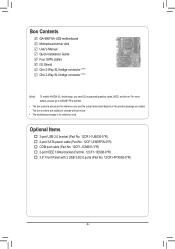
...6 - Box Contents GA-990FXA-UD5 motherboard Motherboard driver disk User's Manual Quick Installation Guide Four SATA cables I/O Shield One 2-Way SLI bridge connector (Note) One 3-Way SLI bridge connector (Note) (Note) To enable NVIDIA SLI technology, you obtain. For more details, please go to GIGABYTE's website. •... The box contents above are subject to change without notice. • The motherboard image is for reference only and the actual items shall depend on the product package you need SLI-supported graphics cards, BIOS, and driver. ...
...6 - Box Contents GA-990FXA-UD5 motherboard Motherboard driver disk User's Manual Quick Installation Guide Four SATA cables I/O Shield One 2-Way SLI bridge connector (Note) One 3-Way SLI bridge connector (Note) (Note) To enable NVIDIA SLI technology, you obtain. For more details, please go to GIGABYTE's website. •... The box contents above are subject to change without notice. • The motherboard image is for reference only and the actual items shall depend on the product package you need SLI-supported graphics cards, BIOS, and driver. ...
Manual
Page 8
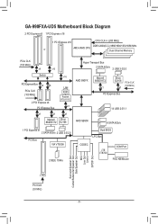
GA-990FXA-UD5 Motherboard Block Diagram 2 PCI Express x8 1 PCI Express x16 1 PCI Express x16 CPU CLK+/- (200 MHz) or DDR3 2000(O.C.)/1866/1600/1333/1066 MHz AM3+/... CLK (100 MHz) PCI Express Bus AMD SB950 14 USB 2.0/1.1 6 SATA 6Gb/s 1 PCI Express x1 2 SATA 6Gb/s 2 USB 3.0/2.0 PCI Bus VIA VT6308 2 IEEE 1394a Dual BIOS LPC Bus CODEC iTE IT8720 COM Port PS/2 KB/Mouse Surround Speaker Out Center/Subwoofer Speaker Out Side Speaker Out MIC Line Out Line In...
GA-990FXA-UD5 Motherboard Block Diagram 2 PCI Express x8 1 PCI Express x16 1 PCI Express x16 CPU CLK+/- (200 MHz) or DDR3 2000(O.C.)/1866/1600/1333/1066 MHz AM3+/... CLK (100 MHz) PCI Express Bus AMD SB950 14 USB 2.0/1.1 6 SATA 6Gb/s 1 PCI Express x1 2 SATA 6Gb/s 2 USB 3.0/2.0 PCI Bus VIA VT6308 2 IEEE 1394a Dual BIOS LPC Bus CODEC iTE IT8720 COM Port PS/2 KB/Mouse Surround Speaker Out Center/Subwoofer Speaker Out Side Speaker Out MIC Line Out Line In...
Manual
Page 12
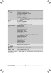
...the CPU/system cooler you install. BIOS ŠŠ 2 x 32 Mbit flash ŠŠ Use of licensed AWARD BIOS ŠŠ Support for DualBIOS™ ŠŠ PnP 1.0a, DMI 2.0, SM BIOS 2.4, ACPI 1.0b Unique Features ŠŠ Support for @BIOS ŠŠ Support for Q-...Flash ŠŠ Support for Xpress BIOS Rescue ŠŠ Support for Download Center...
...the CPU/system cooler you install. BIOS ŠŠ 2 x 32 Mbit flash ŠŠ Use of licensed AWARD BIOS ŠŠ Support for DualBIOS™ ŠŠ PnP 1.0a, DMI 2.0, SM BIOS 2.4, ACPI 1.0b Unique Features ŠŠ Support for @BIOS ŠŠ Support for Q-...Flash ŠŠ Support for Xpress BIOS Rescue ŠŠ Support for Download Center...
Manual
Page 16
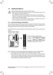
... begin to install the memory: • Make sure that memory of the memory. If you install them in Dual Channel mode. 1. It is installed, the BIOS will double the original memory bandwidth. Enabling Dual Channel memory mode will automatically detect the specifications and capacity of the same capacity, brand, speed, and... mode with two or four memory modules, it is installed. 2. DS/SS DS/SS DDR3_2 DS/SS - Dual Channel mode cannot be used . (Go to GIGABYTE's website for optimum performance. Hardware Installation - 16 -
... begin to install the memory: • Make sure that memory of the memory. If you install them in Dual Channel mode. 1. It is installed, the BIOS will double the original memory bandwidth. Enabling Dual Channel memory mode will automatically detect the specifications and capacity of the same capacity, brand, speed, and... mode with two or four memory modules, it is installed. 2. DS/SS DS/SS DDR3_2 DS/SS - Dual Channel mode cannot be used . (Go to GIGABYTE's website for optimum performance. Hardware Installation - 16 -
Manual
Page 18
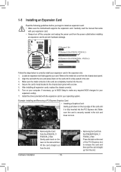
... outlet before you begin to install an expansion card: • Make sure the motherboard supports the expansion card. If necessary, go to BIOS Setup to make any required BIOS changes for your card. Turn on the top edge of the PCI Express slot to release the card and then pull the card...
... outlet before you begin to install an expansion card: • Make sure the motherboard supports the expansion card. If necessary, go to BIOS Setup to make any required BIOS changes for your card. Turn on the top edge of the PCI Express slot to release the card and then pull the card...
Manual
Page 24
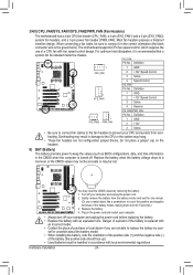
...), a 4-pin (SYS_FAN1) and a 3-pin (SYS_FAN2) system fan headers, and a 3-pin power fan header (PWR_FAN). Overheating may result in damage to keep the values (such as BIOS configurations, date, and time information) in accordance with local environmental regulations. Do not place a jumper cap on the headers. 6) BAT (Battery) The battery provides power...
...), a 4-pin (SYS_FAN1) and a 3-pin (SYS_FAN2) system fan headers, and a 3-pin power fan header (PWR_FAN). Overheating may result in damage to keep the values (such as BIOS configurations, date, and time information) in accordance with local environmental regulations. Do not place a jumper cap on the headers. 6) BAT (Battery) The battery provides power...
Manual
Page 26
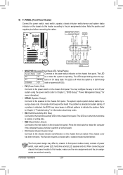
...on when the system is in S1 sleep state. S1 Blinking tem is operating. The LED is off when the system is detected, the BIOS may differ by issuing a beep code. Press the reset switch to restart the computer if the computer freezes and fails to perform a normal...Gray): Connects to the hard drive activity LED on the chassis front panel. When connecting your system using the power switch (refer to Chapter 2, "BIOS Setup," "Power Management Setup," for information about beep codes. • HD (Hard Drive Activity LED, Blue) Connects to the chassis intrusion switch/sensor...
...on when the system is in S1 sleep state. S1 Blinking tem is operating. The LED is off when the system is detected, the BIOS may differ by issuing a beep code. Press the reset switch to restart the computer if the computer freezes and fails to perform a normal...Gray): Connects to the hard drive activity LED on the chassis front panel. When connecting your system using the power switch (refer to Chapter 2, "BIOS Setup," "Power Management Setup," for information about beep codes. • HD (Hard Drive Activity LED, Blue) Connects to the chassis intrusion switch/sensor...
Manual
Page 28
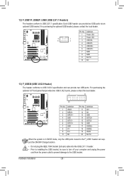
... connector (SATA)(X58A-OC) Pin No. Definition 1 VBUS 11 D2+ 2 SSRX1- 12 D2- 3 SSRX1+ 13 GND 4 GND 14 SSTX2+ 5 SSTX1- 15 SSTX2- 6 SSTX1+ 16 GND BIOS 7 GND 17 SSRX2+ DB_PORT 8 D1- 18 SSRX2- 9 D1+ 19 VBUS 10 NC 20 No Pin When the system is in S4/S5 mode, only the...
... connector (SATA)(X58A-OC) Pin No. Definition 1 VBUS 11 D2+ 2 SSRX1- 12 D2- 3 SSRX1+ 13 GND 4 GND 14 SSTX2+ 5 SSTX1- 15 SSTX2- 6 SSTX1+ 16 GND BIOS 7 GND 17 SSRX2+ DB_PORT 8 D1- 18 SSRX2- 9 D1+ 19 VBUS 10 NC 20 No Pin When the system is in S4/S5 mode, only the...
Manual
Page 30
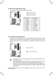
...before turning on the two pins to temporarily short the two pins or use a metal object like a screwdriver to touch the two pins for BIOS configurations). Open: Normal Short: Clear CMOS Values •• Always turn off your computer and unplug the power cord from the jumper. ...Hardware Installation - 30 - date information and BIOS configurations) and reset the CMOS values to factory defaults. Failure to do so may connect a TPM (Trusted Platform Module) to this jumper to ...
...before turning on the two pins to temporarily short the two pins or use a metal object like a screwdriver to touch the two pins for BIOS configurations). Open: Normal Short: Clear CMOS Values •• Always turn off your computer and unplug the power cord from the jumper. ...Hardware Installation - 30 - date information and BIOS configurations) and reset the CMOS values to factory defaults. Failure to do so may connect a TPM (Trusted Platform Module) to this jumper to ...

Manual
Page 31
... to default values. (Refer to prevent system instability or other unexpected results. To upgrade the BIOS, use either the GIGABYTE Q-Flash or @BIOS utility. • Q-Flash allows the user to activate certain system features. BIOS Setup Chapter 2 BIOS Setup BIOS (Basic Input and Output System) records hardware parameters of the system in the main menu of...
... to default values. (Refer to prevent system instability or other unexpected results. To upgrade the BIOS, use either the GIGABYTE Q-Flash or @BIOS utility. • Q-Flash allows the user to activate certain system features. BIOS Setup Chapter 2 BIOS Setup BIOS (Basic Input and Output System) records hardware parameters of the system in the main menu of...
Manual
Page 32
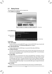
GA-990FXA-UD5 F1a . . . . : BIOS Setup : XpressRecovery2 : Boot Menu : Qflash 04/26/2011-RD990-SB950-7A66FG04C-00 Function Keys... for subsequent access to access the Q-Flash utility directly without entering BIOS Setup. You can be based on page 44. : BIOS SETUP\Q-FLASH Press the key to enter BIOS Setup or to access the Q-Flash utility in Boot Menu. After... system restart, the device boot order will directly boot from the device configured in BIOS Setup. : XPRESS RECOVERY2 If you to set the first boot device without having to back up arrow key...
GA-990FXA-UD5 F1a . . . . : BIOS Setup : XpressRecovery2 : Boot Menu : Qflash 04/26/2011-RD990-SB950-7A66FG04C-00 Function Keys... for subsequent access to access the Q-Flash utility directly without entering BIOS Setup. You can be based on page 44. : BIOS SETUP\Q-FLASH Press the key to enter BIOS Setup or to access the Q-Flash utility in Boot Menu. After... system restart, the device boot order will directly boot from the device configured in BIOS Setup. : XPRESS RECOVERY2 If you to set the first boot device without having to back up arrow key...
Manual
Page 33
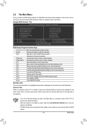
... Saving ESC: Quit F8: Q-Flash Select Item F10: Save & Exit Setup Change CPU's Clock & Voltage F11: Save CMOS to BIOS F12: Load CMOS from BIOS BIOS Setup Program Function Keys Move the selection bar to select an item Execute command or enter the submenu Main Menu: Exit the... settings for the current submenus Access the Q-Flash utility Display system information Save all the changes and exit the BIOS Setup program Save CMOS to BIOS Load CMOS from BIOS Main Menu Help The on-screen description of a highlighted setup option is in a submenu, press to exit the...
... Saving ESC: Quit F8: Q-Flash Select Item F10: Save & Exit Setup Change CPU's Clock & Voltage F11: Save CMOS to BIOS F12: Load CMOS from BIOS BIOS Setup Program Function Keys Move the selection bar to select an item Execute command or enter the submenu Main Menu: Exit the... settings for the current submenus Access the Q-Flash utility Display system information Save all the changes and exit the BIOS Setup program Save CMOS to BIOS Load CMOS from BIOS Main Menu Help The on-screen description of a highlighted setup option is in a submenu, press to exit the...
Manual
Page 34
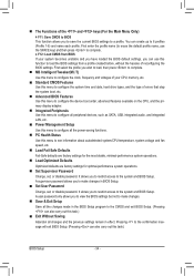
...password. First enter the profile name (to erase the default profile name, use this menu to the system and BIOS Setup. The Functions of reconfiguring the BIOS settings. First select the profile you to restrict access to see information about autodetected system/CPU temperature, system voltage and... configure the system time and date, hard drive types, and the type of errors that stop the system boot, etc. Advanced BIOS Features Use this menu to configure the device boot order, advanced features available on the CPU, and the primary display adapter. Integrated...
...password. First enter the profile name (to erase the default profile name, use this menu to the system and BIOS Setup. The Functions of reconfiguring the BIOS settings. First select the profile you to restrict access to see information about autodetected system/CPU temperature, system voltage and... configure the system time and date, hard drive types, and the type of errors that stop the system boot, etc. Advanced BIOS Features Use this menu to configure the device boot order, advanced features available on the CPU, and the primary display adapter. Integrated...
Manual
Page 35
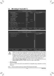
... advanced users only and we recommend you made is dependent on the CPU being used. (Note) This item is dependent on your overall system configurations. BIOS Setup Core Performance Boost (Note) CPB Ratio (Note) Turbo CPB (Note) CPU Host Clock Control x CPU Frequency(MHz) PCIE Clock(MHz) HT Link Width HT...
... advanced users only and we recommend you made is dependent on the CPU being used. (Note) This item is dependent on your overall system configurations. BIOS Setup Core Performance Boost (Note) CPB Ratio (Note) Turbo CPB (Note) CPU Host Clock Control x CPU Frequency(MHz) PCIE Clock(MHz) HT Link Width HT...
Manual
Page 36
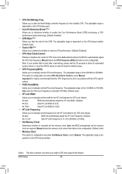
... on the CPU being used. Auto sets the PCIe clock frequency to standard 100 MHz. (Default: Auto) HT Link Width Allows you to Manual. Auto BIOS will automatically adjust the HT Link Width. (Default) 8 bit Sets HT Link Width to 8 bit. 16 bit Sets HT Link Width to be configurable. ... for the CPB. Manual allows the CPU Frequency (MHz) item below to 16 bit. The adjustable range is set the CPU host frequency. Auto BIOS will automatically adjust the HT Link Frequency. (Default) x1~x10 Sets HT Link Frequency to 150 MHz. HT Link Frequency Allows you to default values...
... on the CPU being used. Auto sets the PCIe clock frequency to standard 100 MHz. (Default: Auto) HT Link Width Allows you to Manual. Auto BIOS will automatically adjust the HT Link Width. (Default) 8 bit Sets HT Link Width to 8 bit. 16 bit Sets HT Link Width to be configurable. ... for the CPB. Manual allows the CPU Frequency (MHz) item below to 16 bit. The adjustable range is set the CPU host frequency. Auto BIOS will automatically adjust the HT Link Frequency. (Default) x1~x10 Sets HT Link Frequency to 150 MHz. HT Link Frequency Allows you to default values...
Manual
Page 37
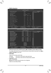
... mode. Unganged Sets memory control mode to two single-channel. (Default) DDR3 Timing Items Manual allows all DDR3 Timing items below to single dual-channel. BIOS Setup Auto 9T 9T Auto 9T 9T Auto 9T 9T Auto 24T 24T Auto 5T 5T Auto 110ns 110ns Auto -- -- Auto 10T 10T Auto 5T...
... mode. Unganged Sets memory control mode to two single-channel. (Default) DDR3 Timing Items Manual allows all DDR3 Timing items below to single dual-channel. BIOS Setup Auto 9T 9T Auto 9T 9T Auto 9T 9T Auto 24T 24T Auto 5T 5T Auto 110ns 110ns Auto -- -- Auto 10T 10T Auto 5T...
Manual
Page 38
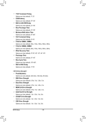
..., 1.25x, 1.5x, 2.0x. Data Drive Strength Options are : Auto (default), 90ns, 110ns, 160ns, 300ns, 350ns. CS/ODT Drive Strength Options are : Auto (default), 10T~56T. BIOS Setup - 38 - Row Cycle Time Options are : Auto (default), 1.0x, 1.25x, 1.5x, 2.0x. Minimum RAS Active Time Options are : Auto (default), 4T~9T. TwTr Command...
..., 1.25x, 1.5x, 2.0x. Data Drive Strength Options are : Auto (default), 90ns, 110ns, 160ns, 300ns, 350ns. CS/ODT Drive Strength Options are : Auto (default), 10T~56T. BIOS Setup - 38 - Row Cycle Time Options are : Auto (default), 1.0x, 1.25x, 1.5x, 2.0x. Minimum RAS Active Time Options are : Auto (default), 4T~9T. TwTr Command...


