Manual
Page 10
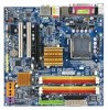
... Slots Š 1 PCI Express x16 slot Š 1 PCI Express x1 slot Š 2 PCI slots Internal Connectors Š 1 24-pin ATX power connector Š 1 4-pin ATX 12V power connector Š 1 floppy connector Š 1 IDE connector Š 6 SATA 3Gb/s connectors Š 1 CPU fan connector Š 1 system fan connector Š 1 front panel connector Š 1 front audio connector Š 1 CD In connector Š 1 power LED connector "*" Only the GA-965GM-DS2 adopts All-Solid Capacitor design. GA-965GM-(D)S2 Motherboard - 10 - Supports data striping (RAID 0), mirroring (RAID...
... Slots Š 1 PCI Express x16 slot Š 1 PCI Express x1 slot Š 2 PCI slots Internal Connectors Š 1 24-pin ATX power connector Š 1 4-pin ATX 12V power connector Š 1 floppy connector Š 1 IDE connector Š 6 SATA 3Gb/s connectors Š 1 CPU fan connector Š 1 system fan connector Š 1 front panel connector Š 1 front audio connector Š 1 CD In connector Š 1 power LED connector "*" Only the GA-965GM-DS2 adopts All-Solid Capacitor design. GA-965GM-(D)S2 Motherboard - 10 - Supports data striping (RAID 0), mirroring (RAID...

Manual
Page 13
... used for detailed installation instructions, please refer to the CPU cooler installation section of the user manual) Fig. 5 Please check the back of the heat paste. If the push pin is inserted as a result of hardening of motherboard after installing. Fig. 6 Finally, please attach the power connector of the CPU cooler to the CPU as the picture, the installation is to the pin hole on the motherboard...
... used for detailed installation instructions, please refer to the CPU cooler installation section of the user manual) Fig. 5 Please check the back of the heat paste. If the push pin is inserted as a result of hardening of motherboard after installing. Fig. 6 Finally, please attach the power connector of the CPU cooler to the CPU as the picture, the installation is to the pin hole on the motherboard...
Manual
Page 15
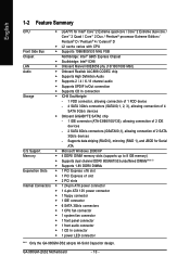
... use memory modules of identical brand, size, chips, and speed), you want to Flex memory mode operation will double. Hardware Installation The following explanations due to the limitation of the same color. The GA-965GM-DS2 / GA-965GM-S2 includes 4 DIMM sockets, and each Channel has two DIMM sockets as following: Channel 0 : DDRII1, DDRII2 Channel 1 : DDRII3, DDRII4 If you must install them into DIMM sockets of Intel chipset specifications. 1. After operating the Dual Channel Technology...
... use memory modules of identical brand, size, chips, and speed), you want to Flex memory mode operation will double. Hardware Installation The following explanations due to the limitation of the same color. The GA-965GM-DS2 / GA-965GM-S2 includes 4 DIMM sockets, and each Channel has two DIMM sockets as following: Channel 0 : DDRII1, DDRII2 Channel 1 : DDRII3, DDRII4 If you must install them into DIMM sockets of Intel chipset specifications. 1. After operating the Dual Channel Technology...

Manual
Page 18
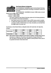
... audio software. Microphone must be connected to the 2-/4-/6-/8- channel audio setup steps for detailed software configuration information. 1-7 Connectors Introduction 1 3 2 6 5 11 18 12 10 13 17 9 16 4 1) ATX_12V 2) ATX (Power Connector) 3) CPU_FAN 4) SYS_FAN 5) IDE 6) FDD 7) SATAII0 / 1 / 2 / 3 8) GSATAII0/1 9) PWR_LED 10) F_PANEL 15 19 14 78 11) F_AUDIO 12) CD_IN 13) SPDIF_IO 14) F_USB1 / F_USB2 / F_USB3 15) F1_1394 / F2_1394 16) COMB 17) CI 18) CLR_CMOS 19) BATTERY GA-965GM-(D)S2 Motherboard...
... audio software. Microphone must be connected to the 2-/4-/6-/8- channel audio setup steps for detailed software configuration information. 1-7 Connectors Introduction 1 3 2 6 5 11 18 12 10 13 17 9 16 4 1) ATX_12V 2) ATX (Power Connector) 3) CPU_FAN 4) SYS_FAN 5) IDE 6) FDD 7) SATAII0 / 1 / 2 / 3 8) GSATAII0/1 9) PWR_LED 10) F_PANEL 15 19 14 78 11) F_AUDIO 12) CD_IN 13) SPDIF_IO 14) F_USB1 / F_USB2 / F_USB3 15) F1_1394 / F2_1394 16) COMB 17) CI 18) CLR_CMOS 19) BATTERY GA-965GM-(D)S2 Motherboard...
Manual
Page 20
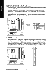
... to two IDE devices (hard drive or optical drive). The black connector wire is the ground wire (GND). Pin No. Before attaching the IDE cable, please take note of the foolproof groove in the IDE connector. 40 39 GA-965GM-(D)S2 Motherboard - 20 - 2 1 Definition 1 1 GND 2 +12V/Speed Control 3 Sense 4 Speed Control 5) IDE (IDE Connector) An IDE device connects to prevent CPU damage or system hanging caused by overheating. English 3/4) CPU_FAN / SYS_FAN (Cooler Fan Power Connector) The cooler fan power connector supplies a +12V power voltage via an IDE connector. Most...
... to two IDE devices (hard drive or optical drive). The black connector wire is the ground wire (GND). Pin No. Before attaching the IDE cable, please take note of the foolproof groove in the IDE connector. 40 39 GA-965GM-(D)S2 Motherboard - 20 - 2 1 Definition 1 1 GND 2 +12V/Speed Control 3 Sense 4 Speed Control 5) IDE (IDE Connector) An IDE device connects to prevent CPU damage or system hanging caused by overheating. English 3/4) CPU_FAN / SYS_FAN (Cooler Fan Power Connector) The cooler fan power connector supplies a +12V power voltage via an IDE connector. Most...

Manual
Page 21
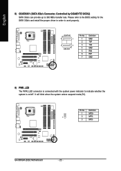
Please refer to the BIOS setting for the SATA 3Gb/s and install the proper driver in the FDD connector. 34 33 2 1 7) SATAII0 / 1 / 2 / 3 (SATA 3Gb/s Connector, Controlled by Intel ICH8) SATA 3Gb/s can provide up to 300 MB/s transfer rate. The types of the foolproof groove in order to the FDD drive. SATAII2 7 17 SATAII0 1 1 71 7 SATAII3 SATAII1 Pin No. 1 2 3 4 5 6 7 Definition GND TXP TXN GND...
Please refer to the BIOS setting for the SATA 3Gb/s and install the proper driver in the FDD connector. 34 33 2 1 7) SATAII0 / 1 / 2 / 3 (SATA 3Gb/s Connector, Controlled by Intel ICH8) SATA 3Gb/s can provide up to 300 MB/s transfer rate. The types of the foolproof groove in order to the FDD drive. SATAII2 7 17 SATAII0 1 1 71 7 SATAII3 SATAII1 Pin No. 1 2 3 4 5 6 7 Definition GND TXP TXN GND...
Manual
Page 22
.../s and install the proper driver in order to 300 MB/s transfer rate. GSATAII0 7 1 1 7 GSATAII1 Pin No. 1 2 3 4 5 6 7 Definition GND TXP TXN GND RXN RXP GND 9) PWR_LED The PWR_LED connector is connected with the system power indicator to indicate whether the system is on/off. Pin No. Definition 1 MPD+ 1 2 MPD- 3 MPD- It will blink when the system enters suspend mode(S1). GA-965GM-(D)S2 Motherboard...
.../s and install the proper driver in order to 300 MB/s transfer rate. GSATAII0 7 1 1 7 GSATAII1 Pin No. 1 2 3 4 5 6 7 Definition GND TXP TXN GND RXN RXP GND 9) PWR_LED The PWR_LED connector is connected with the system power indicator to indicate whether the system is on/off. Pin No. Definition 1 MPD+ 1 2 MPD- 3 MPD- It will blink when the system enters suspend mode(S1). GA-965GM-(D)S2 Motherboard...
Manual
Page 32
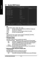
... device detection. IDE Channel 0/1 Master IDE HDD Auto-Detection Press "Enter" to automatically detect IDE/SATA devices during POST(default) None Select this option for the hard drive. Extended IDE Drive. You can manually input the correct settings Access Mode Use this option for faster system start up. For example, 1 p.m. is calculated base on the 24-hour military-time clock. English 2-1 Standard CMOS Features Date (mm:dd:yy) Time (hh:mm:ss) CMOS Setup Utility-Copyright (C) 1984-2006 Award Software Standard CMOS...
... device detection. IDE Channel 0/1 Master IDE HDD Auto-Detection Press "Enter" to automatically detect IDE/SATA devices during POST(default) None Select this option for the hard drive. Extended IDE Drive. You can manually input the correct settings Access Mode Use this option for faster system start up. For example, 1 p.m. is calculated base on the 24-hour military-time clock. English 2-1 Standard CMOS Features Date (mm:dd:yy) Time (hh:mm:ss) CMOS Setup Utility-Copyright (C) 1984-2006 Award Software Standard CMOS...

Manual
Page 36
...IDE mode. USB Keyboard Support Enabled Enable USB Keyboard Support. Azalia Codec Auto Auto detect Azalia audio function. (Default value) Disabled Disable Azalia audio function. English 2-3 Integrated Peripherals CMOS Setup Utility-Copyright (C) 1984-2006 Award Software Integrated Peripherals SATA Port0-3 Native Mode USB Controller USB 2.0 Controller USB Keyboard Support USB Mouse Support Legacy USB storage detect Azalia Codec Onboard H/W 1394 Onboard H/W LAN ` SMART LAN OnBoard LAN Boot ROM Onboard SATA/IDE Device Onboard SATA/IDE Ctrl Mode Onboard Serial Port 1 Onboard Serial Port...
...IDE mode. USB Keyboard Support Enabled Enable USB Keyboard Support. Azalia Codec Auto Auto detect Azalia audio function. (Default value) Disabled Disable Azalia audio function. English 2-3 Integrated Peripherals CMOS Setup Utility-Copyright (C) 1984-2006 Award Software Integrated Peripherals SATA Port0-3 Native Mode USB Controller USB 2.0 Controller USB Keyboard Support USB Mouse Support Legacy USB storage detect Azalia Codec Onboard H/W 1394 Onboard H/W LAN ` SMART LAN OnBoard LAN Boot ROM Onboard SATA/IDE Device Onboard SATA/IDE Ctrl Mode Onboard Serial Port 1 Onboard Serial Port...
Manual
Page 38
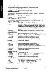
.../IRQ3. (Default value) Enable onboard Serial port 2 and address is 3BC/IRQ7. GA-965GM-(D)S2 Motherboard - 38 - ing and hot plug. Onboard Serial Port 1 Auto BIOS will automatically setup the port 2 address. Disable onboard Serial port 2. Using Parallel port as Extended Capabilities Port. Disable this function. (Default value) Onboard SATA/IDE Device This function allows users to enable or disable the SATA/IDE ports controlled by the GIGABYTE SATA2 controller. RAID/IDE Set the SATA channel to RAID mode and IDE channel to AHCI mode. Onboard Serial Port 2 Auto 3F8/IRQ4...
.../IRQ3. (Default value) Enable onboard Serial port 2 and address is 3BC/IRQ7. GA-965GM-(D)S2 Motherboard - 38 - ing and hot plug. Onboard Serial Port 1 Auto BIOS will automatically setup the port 2 address. Disable onboard Serial port 2. Using Parallel port as Extended Capabilities Port. Disable this function. (Default value) Onboard SATA/IDE Device This function allows users to enable or disable the SATA/IDE ports controlled by the GIGABYTE SATA2 controller. RAID/IDE Set the SATA channel to RAID mode and IDE channel to AHCI mode. Onboard Serial Port 2 Auto 3F8/IRQ4...
Manual
Page 45
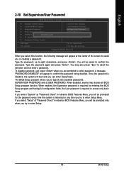
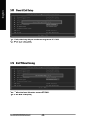
... characters, and press . Type the password again and press . English 2-10 Set Supervisor/User Password CMOS Setup Utility-Copyright (C) 1984-2006 Award Software ` Standard CMOS Features ` Advanced BIOS Features ` Integrated Peripherals ` Power Management Setup ` PnP/PCI ConfigurationEsnter Password: ` PC Health Status ` Frequency/Voltage Control Load Fail-Safe Defaults Load Optimized Defaults Set Supervisor Password Set User Password Save & Exit Setup Exit Without Saving ESC: Quit F8: Q-Flash KLJI: Select Item F10: Save & Exit Setup Change/Set/Disable Password When you select this...
... characters, and press . Type the password again and press . English 2-10 Set Supervisor/User Password CMOS Setup Utility-Copyright (C) 1984-2006 Award Software ` Standard CMOS Features ` Advanced BIOS Features ` Integrated Peripherals ` Power Management Setup ` PnP/PCI ConfigurationEsnter Password: ` PC Health Status ` Frequency/Voltage Control Load Fail-Safe Defaults Load Optimized Defaults Set Supervisor Password Set User Password Save & Exit Setup Exit Without Saving ESC: Quit F8: Q-Flash KLJI: Select Item F10: Save & Exit Setup Change/Set/Disable Password When you select this...
Manual
Page 46
... all Data Type "Y" will return to Setup Utility. GA-965GM-(D)S2 Motherboard - 46 - Type "N" will quit the Setup Utility without saving to RTC CMOS. English 2-11 Save & Exit Setup CMOS Setup Utility-Copyright (C) 1984-2006 Award Software ` Standard CMOS Features Load Fail-Safe Defaults ` Advanced BIOS Features Load Optimized Defaults ` Integrated Peripherals Set Supervisor Password ` Power Management Setup Save to CMOS and EXIT (SYe/tNU)?seYr Password ` PnP/PCI Configurations Save & Exit Setup ` PC Health Status Exit Without Saving ` Frequency/Voltage Control ESC: Quit...
... all Data Type "Y" will return to Setup Utility. GA-965GM-(D)S2 Motherboard - 46 - Type "N" will quit the Setup Utility without saving to RTC CMOS. English 2-11 Save & Exit Setup CMOS Setup Utility-Copyright (C) 1984-2006 Award Software ` Standard CMOS Features Load Fail-Safe Defaults ` Advanced BIOS Features Load Optimized Defaults ` Integrated Peripherals Set Supervisor Password ` Power Management Setup Save to CMOS and EXIT (SYe/tNU)?seYr Password ` PnP/PCI Configurations Save & Exit Setup ` PC Health Status Exit Without Saving ` Frequency/Voltage Control ESC: Quit...

Manual
Page 47
... defaulted. If not, please double click the CD-ROM device icon in Windows XP. Please pick the item that you can press "Xpress Install" to install all the drivers that came with your motherboard into your CD-ROM drive, the driver CD-title will restart your system the "Xpress Install" will show the installation guide. Some device drivers will auto start and show a question mark "?" For USB2.0 driver support under "Device...
... defaulted. If not, please double click the CD-ROM device icon in Windows XP. Please pick the item that you can press "Xpress Install" to install all the drivers that came with your motherboard into your CD-ROM drive, the driver CD-title will restart your system the "Xpress Install" will show the installation guide. Some device drivers will auto start and show a question mark "?" For USB2.0 driver support under "Device...

Manual
Page 52
... restoration of system memory 3. Save the settings and exit the BIOS Setup. If you complete installations of OS and all required drivers as well as software. After Xpress Recovery2 is able to startup XpressRecovery2..... VESA-supported VGA cards How to enter Xpress Recovery2. Press any key to back up data on hard disks on . . . Boot from CD-ROM for 965GM-DS2 F1 . . . . :BIOS Setup/Q-Flash, : Xpress Recovery2, : Boot Menu 10/12/2006...
... restoration of system memory 3. Save the settings and exit the BIOS Setup. If you complete installations of OS and all required drivers as well as software. After Xpress Recovery2 is able to startup XpressRecovery2..... VESA-supported VGA cards How to enter Xpress Recovery2. Press any key to back up data on hard disks on . . . Boot from CD-ROM for 965GM-DS2 F1 . . . . :BIOS Setup/Q-Flash, : Xpress Recovery2, : Boot Menu 10/12/2006...

Manual
Page 55
... Award Software Standard CMOS Features Advanced BIOS Features Integrated Peripherals Power Management Setup PnP/PCI Configurations PC Health Status MB Intelligent Tweaker(M.I.T.) ESC: Quit F8: Dual BIOS/Q-Flash Select Language Load Fail-Safe Defaults Load Optimized Defaults Set Supervisor Password Set User Password Save & Exit Setup Exit Without Saving F3: Change Language F10: Save & Exit Setup Time, Date, Hard Disk Type... Task menu for Dual BIOS utility: Contains the names of the following key components. Blocking a task and pressing Enter key on your keyboard to enable...
... Award Software Standard CMOS Features Advanced BIOS Features Integrated Peripherals Power Management Setup PnP/PCI Configurations PC Health Status MB Intelligent Tweaker(M.I.T.) ESC: Quit F8: Dual BIOS/Q-Flash Select Language Load Fail-Safe Defaults Load Optimized Defaults Set Supervisor Password Set User Password Save & Exit Setup Exit Without Saving F3: Change Language F10: Save & Exit Setup Time, Date, Hard Disk Type... Task menu for Dual BIOS utility: Contains the names of the following key components. Blocking a task and pressing Enter key on your keyboard to enable...

Manual
Page 64
... BIOS Setup and set this section may not show the exact settings for the SATA hard drive(s)/RAID array. CMOS Setup Utility-Copyright (C) 1984-2006 Award Software Integrated Peripherals SATA Port0-3 Native Mode USB Controller USB 2.0 Controller USB Keyboard Support USB Mouse Support Legacy USB storage detect Azalia Codec Onboard H/W 1394 Onboard H/W LAN SMART LAN OnBoard LAN Boot ROM Onboard SATA/IDE Device Onboard SATA/IDE Ctrl Mode Onboard Serial Port 1 Onboard Serial Port 2 Onboard Parallel Port Parallel Port Mode [Disabled] [Enabled] [Enabled] [Disabled] [Disabled] [Enabled] [Auto...
... BIOS Setup and set this section may not show the exact settings for the SATA hard drive(s)/RAID array. CMOS Setup Utility-Copyright (C) 1984-2006 Award Software Integrated Peripherals SATA Port0-3 Native Mode USB Controller USB 2.0 Controller USB Keyboard Support USB Mouse Support Legacy USB storage detect Azalia Codec Onboard H/W 1394 Onboard H/W LAN SMART LAN OnBoard LAN Boot ROM Onboard SATA/IDE Device Onboard SATA/IDE Ctrl Mode Onboard Serial Port 1 Onboard Serial Port 2 Onboard Parallel Port Parallel Port Mode [Disabled] [Enabled] [Enabled] [Disabled] [Disabled] [Enabled] [Auto...
Manual
Page 72
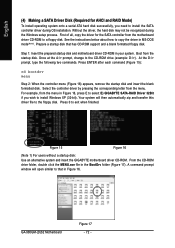
... the driver for AHCI and RAID Mode) To install operating system onto a serial ATA hard disk successfully, you wish to install Windows XP (32-bit). See the instructions below about how to copy the driver in Figure 16, press E to select E) GIGABYTE SATA-RAID Driver 32Bit if you need to a floppy disk. At the D:\> prompt, type the following two commands. Select the controller driver by pressing the corresponding letter from the startup disk. GA-965GM-(D)S2 Motherboard...
... the driver for AHCI and RAID Mode) To install operating system onto a serial ATA hard disk successfully, you wish to install Windows XP (32-bit). See the instructions below about how to copy the driver in Figure 16, press E to select E) GIGABYTE SATA-RAID Driver 32Bit if you need to a floppy disk. At the D:\> prompt, type the following two commands. Select the controller driver by pressing the corresponding letter from the startup disk. GA-965GM-(D)S2 Motherboard...
Manual
Page 73
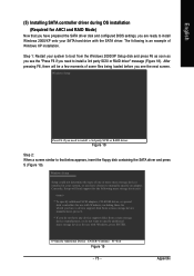
...-ROM drives, or special disk controllers for use with Windows, including those for which you have chosen to specify additional mass storage devices for use with the SATA driver. Windows Setup Setup could not determine the type of Windows XP installation. After pressing F6, there will load support for the following is an example of one or more mass storage devices installed in your SATA hard drive with Windows, press ENTER. English (5) Installing SATA controller driver during OS installation (Required for AHCI and RAID Mode...
...-ROM drives, or special disk controllers for use with Windows, including those for which you have chosen to specify additional mass storage devices for use with the SATA driver. Windows Setup Setup could not determine the type of Windows XP installation. After pressing F6, there will load support for the following is an example of one or more mass storage devices installed in your SATA hard drive with Windows, press ENTER. English (5) Installing SATA controller driver during OS installation (Required for AHCI and RAID Mode...
Manual
Page 74
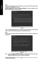
... storage devices for use with Windows, using a device support disk provided by an adapter manufacturer. Use the ARROW keys to the previous screen. GA-965GM-(D)S2 Motherboard - 74 - Select the SCSI Adapter you set the OnBoard SATA/IDE Ctrl Mode item in the floppy disk, a controller menu similar to Figure 20 below will begin to load the SATA driver from the following mass storage device(s): GIGABYTE GBB36X RAID Controller(Windows 2K/XP/2003) * To specify additional SCSI adapters, CD-ROM drives, or special disk controllers for use with Windows...
... storage devices for use with Windows, using a device support disk provided by an adapter manufacturer. Use the ARROW keys to the previous screen. GA-965GM-(D)S2 Motherboard - 74 - Select the SCSI Adapter you set the OnBoard SATA/IDE Ctrl Mode item in the floppy disk, a controller menu similar to Figure 20 below will begin to load the SATA driver from the following mass storage device(s): GIGABYTE GBB36X RAID Controller(Windows 2K/XP/2003) * To specify additional SCSI adapters, CD-ROM drives, or special disk controllers for use with Windows...
Manual
Page 81
... and turn on to the Clear CMOS steps in new BIOS version. Save changes and reboot the system. Answer: If your board doesn't have such jumper, you can use a metal object to see some boards, a small amount of electricity is equipped with power/amplifier and try again later. Please press Ctrl and F1 keys after updating BIOS. AWARD BIOS Beep Codes 1 short: System boots successfully 2 short: CMOS setting error 1 long 1 short: DRAM or M/B error 1 long 2 short: Monitor or display card error 1 long 3 short: Keyboard error 1 long 9 short: BIOS ROM error Continuous long beeps...
... and turn on to the Clear CMOS steps in new BIOS version. Save changes and reboot the system. Answer: If your board doesn't have such jumper, you can use a metal object to see some boards, a small amount of electricity is equipped with power/amplifier and try again later. Please press Ctrl and F1 keys after updating BIOS. AWARD BIOS Beep Codes 1 short: System boots successfully 2 short: CMOS setting error 1 long 1 short: DRAM or M/B error 1 long 2 short: Monitor or display card error 1 long 3 short: Keyboard error 1 long 9 short: BIOS ROM error Continuous long beeps...


