Manual
Page 4
...GA-945PL-DS3/GA-945PL-S3 Motherboard Layout 7 Block Diagram ...8 Chapter 1 Hardware Installation 9 1-1 Considerations Prior to Installation 9 1-2 Feature Summary 10 1-3 Installation of the CPU and CPU Cooler 12 1-3-1 Installation of the CPU 12 1-3-2 Installation of the Cooler 13 1-4 Installation of Memory 14 1-5 Installation of Expansion Cards 16 1-6 I/O Back Panel Introduction 17 1-7 Connectors Introduction 18 Chapter 2 BIOS... Setup 29 The Main Menu (For example: GA-945PL-DS3 BIOS Ver.: F2e 30 2-1 Standard CMOS Features 32 2-2 Advanced BIOS Features 34 2-3 ...
...GA-945PL-DS3/GA-945PL-S3 Motherboard Layout 7 Block Diagram ...8 Chapter 1 Hardware Installation 9 1-1 Considerations Prior to Installation 9 1-2 Feature Summary 10 1-3 Installation of the CPU and CPU Cooler 12 1-3-1 Installation of the CPU 12 1-3-2 Installation of the Cooler 13 1-4 Installation of Memory 14 1-5 Installation of Expansion Cards 16 1-6 I/O Back Panel Introduction 17 1-7 Connectors Introduction 18 Chapter 2 BIOS... Setup 29 The Main Menu (For example: GA-945PL-DS3 BIOS Ver.: F2e 30 2-1 Standard CMOS Features 32 2-2 Advanced BIOS Features 34 2-3 ...
Manual
Page 5
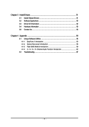
Chapter 3 Install Drivers 51 3-1 Install Chipset Drivers 51 3-2 SoftwareApplications 52 3-3 Driver CD Information 52 3-4 Hardware Information 53 3-5 Contact Us ...53 Chapter 4 Appendix 55 4-1 Unique Software Utilities 55 4-1-1 EasyTune 5 Introduction 55 4-1-2 Xpress Recovery2 Introduction 56 4-1-3 Flash BIOS Method Introduction 58 4-1-4 2- / 4- / 6- / 8- Channel Audio Function Introduction 62 4-2 Troubleshooting 67 - 5 -
Chapter 3 Install Drivers 51 3-1 Install Chipset Drivers 51 3-2 SoftwareApplications 52 3-3 Driver CD Information 52 3-4 Hardware Information 53 3-5 Contact Us ...53 Chapter 4 Appendix 55 4-1 Unique Software Utilities 55 4-1-1 EasyTune 5 Introduction 55 4-1-2 Xpress Recovery2 Introduction 56 4-1-3 Flash BIOS Method Introduction 58 4-1-4 2- / 4- / 6- / 8- Channel Audio Function Introduction 62 4-2 Troubleshooting 67 - 5 -
Manual
Page 7
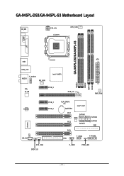
GA-945PL-DS3/GA-945PL-S3 Motherboard Layout KB_MS ATX_12V LGA775 CPU_FAN GA-945PL-DS3/GA-945PL-S3 COMA LPT ATX USB USB_LAN F_AUDIO AUDIO NB_FAN Intel® 945PL RTL 8111B PCIE_3 PCIE_16 DDRII1 DDRII2 DDRII3 DDRII4 PWR_FAN CODEC PCIE_1 PCIE_2 IT8718 CI CD_IN SYS _FAN SPDIF_IO CLR_CMOS BATTERY Intel® ICH7 PCI1 SATAII0 BIOS PCI2 SATAII1 PCI3 FDD F_USB2 SATAII2 SATAII3 IDE1 F_PANEL F_USB1 PWR_LED - 7 -
GA-945PL-DS3/GA-945PL-S3 Motherboard Layout KB_MS ATX_12V LGA775 CPU_FAN GA-945PL-DS3/GA-945PL-S3 COMA LPT ATX USB USB_LAN F_AUDIO AUDIO NB_FAN Intel® 945PL RTL 8111B PCIE_3 PCIE_16 DDRII1 DDRII2 DDRII3 DDRII4 PWR_FAN CODEC PCIE_1 PCIE_2 IT8718 CI CD_IN SYS _FAN SPDIF_IO CLR_CMOS BATTERY Intel® ICH7 PCI1 SATAII0 BIOS PCI2 SATAII1 PCI3 FDD F_USB2 SATAII2 SATAII3 IDE1 F_PANEL F_USB1 PWR_LED - 7 -
Manual
Page 8
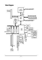
Block Diagram PCIe CLK (100 MHz) LGA775 Processor CPU CLK+/-(200/133 MHz) PCI Express x16 RJ45 RTL 8111B x1 PCI Express Bus x1 x1 x1 PCIe CLK (100 MHz) 3 PCI Express x1 PCI Bus Host Interface Intel® 945PL DDRII 400/533 MHz DIMM Dual Channel Memory MCH CLK(200/133 MHz) BIOS 4 SATA 3Gb/s Intel® ATA33/66/100 ICH7 IDE1 Channel Floppy IT8718 LPT Port COM Port CODEC 8 USB Ports PS/2 KB/Mouse Surround Speaker Out Center/Subwoofer Speaker Out Side Speaker Out MIC Line-Out Line-In SPDIF In SPDIF Out 3 PCI PCI CLK (33 MHz) - 8 -
Block Diagram PCIe CLK (100 MHz) LGA775 Processor CPU CLK+/-(200/133 MHz) PCI Express x16 RJ45 RTL 8111B x1 PCI Express Bus x1 x1 x1 PCIe CLK (100 MHz) 3 PCI Express x1 PCI Bus Host Interface Intel® 945PL DDRII 400/533 MHz DIMM Dual Channel Memory MCH CLK(200/133 MHz) BIOS 4 SATA 3Gb/s Intel® ATA33/66/100 ICH7 IDE1 Channel Floppy IT8718 LPT Port COM Port CODEC 8 USB Ports PS/2 KB/Mouse Surround Speaker Out Center/Subwoofer Speaker Out Side Speaker Out MIC Line-Out Line-In SPDIF In SPDIF Out 3 PCI PCI CLK (33 MHz) - 8 -
Manual
Page 11
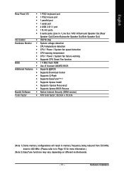
... temperature Š CPU / Power / System fan failure warning Š Supports CPU Smart Fan function BIOS Š 1 4 Mbit flash ROM Š Use of licensed AWARD BIOS Additional Features Š Supports @BIOS Š Supports Download Center Š Supports Q-Flash Š Supports EasyTune(Note 2) Š Supports... Xpress Install Š Supports Xpress Recovery2 Š Supports Xpress BIOS Rescue Bundle Software Š Norton Internet Security (OEM version) Form Factor Š ATX form factor; 30.5cm x 19.3cm ...
... temperature Š CPU / Power / System fan failure warning Š Supports CPU Smart Fan function BIOS Š 1 4 Mbit flash ROM Š Use of licensed AWARD BIOS Additional Features Š Supports @BIOS Š Supports Download Center Š Supports Q-Flash Š Supports EasyTune(Note 2) Š Supports... Xpress Install Š Supports Xpress Recovery2 Š Supports Xpress BIOS Rescue Bundle Software Š Norton Internet Security (OEM version) Form Factor Š ATX form factor; 30.5cm x 19.3cm ...
Manual
Page 12
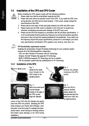
...and permanent damage of the CPU socket. Please make sure the CPU cooler is not recommended that the motherboard supports the CPU. 2. BIOS: A BIOS that supports HT Technology - Please make sure that the system bus frequency be set the CPU host frequency in the wrong direction,... the CPU. Fig. 3 Notice the small gold colored triangle located on the CPU prior to the CPU during installation.) GA-945PL-(D)S3 Motherboard - 12 - HT functionality requirement content : Enabling the functionality of heat sink paste between your thumb and forefinger, carefully place it enabled -...
...and permanent damage of the CPU socket. Please make sure the CPU cooler is not recommended that the motherboard supports the CPU. 2. BIOS: A BIOS that supports HT Technology - Please make sure that the system bus frequency be set the CPU host frequency in the wrong direction,... the CPU. Fig. 3 Notice the small gold colored triangle located on the CPU prior to the CPU during installation.) GA-945PL-(D)S3 Motherboard - 12 - HT functionality requirement content : Enabling the functionality of heat sink paste between your thumb and forefinger, carefully place it enabled -...
Manual
Page 14
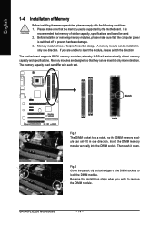
...DIMM module. Notch DDRII Fig.1 The DIMM socket has a notch, so the DIMM memory module can be installed in only one direction. GA-945PL-(D)S3 Motherboard - 14 - It is switched off to remove the DIMM module. Before installing or removing memory modules, please make sure that ... that the memory used can be used. 2. Memory modules have a foolproof insertion design. The motherboard supports DDRII memory modules, whereby BIOS will automatically detect memory capacity and specifications. Then push it down. Reverse the installation steps when you are designed so that memory of...
...DIMM module. Notch DDRII Fig.1 The DIMM socket has a notch, so the DIMM memory module can be installed in only one direction. GA-945PL-(D)S3 Motherboard - 14 - It is switched off to remove the DIMM module. Before installing or removing memory modules, please make sure that ... that the memory used can be used. 2. Memory modules have a foolproof insertion design. The motherboard supports DDRII memory modules, whereby BIOS will automatically detect memory capacity and specifications. Then push it down. Reverse the installation steps when you are designed so that memory of...
Manual
Page 16
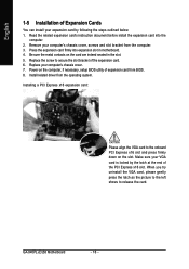
...of Expansion Cards You can install your expansion card by following the steps outlined below: 1. GA-945PL-(D)S3 Motherboard - 16 - Be sure the metal contacts on the card are indeed seated in motherboard. 4. Install related driver from BIOS. 8. When you try uninstall the VGA card, please gently press the latch as the...: Please align the VGA card to the onboard PCI Express x16 slot and press firmly down on the computer, if necessary, setup BIOS utility of the expansion card. 6. Replace the screw to release the card. Remove your computer's chassis cover. 7. Power on the slot.
...of Expansion Cards You can install your expansion card by following the steps outlined below: 1. GA-945PL-(D)S3 Motherboard - 16 - Be sure the metal contacts on the card are indeed seated in motherboard. 4. Install related driver from BIOS. 8. When you try uninstall the VGA card, please gently press the latch as the...: Please align the VGA card to the onboard PCI Express x16 slot and press firmly down on the computer, if necessary, setup BIOS utility of the expansion card. 6. Replace the screw to release the card. Remove your computer's chassis cover. 7. Power on the slot.
Manual
Page 22
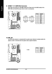
GA-945PL-(D)S3 Motherboard - 22 - Pin No. Please refer to the BIOS setting for the SATA 3Gb/s and install the proper driver in order to indicate whether the system is on/off. Definition 1 1 MPD+ 2 MPD- 3 MPD- It ...
GA-945PL-(D)S3 Motherboard - 22 - Pin No. Please refer to the BIOS setting for the SATA 3Gb/s and install the proper driver in order to indicate whether the system is on/off. Definition 1 1 MPD+ 2 MPD- 3 MPD- It ...
Manual
Page 26
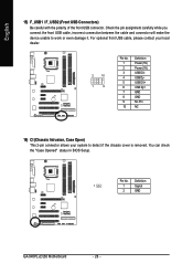
You can check the "Case Opened" status in BIOS Setup. Pin No. For optional front USB cable, please contact your local dealer. 2 10 1 9 Pin No. 1 2 3 4 5 6 7 8 9 10 Definition Power (5V) Power (5V) USB DXUSB DyUSB ... GND No Pin NC 16) CI (Chassis Intrusion, Case Open) This 2-pin connector allows your system to work or even damage it. Definition 1 1 Signal 2 GND GA-945PL-(D)S3 Motherboard - 26 - Check the pin assignment carefully while you connect the front USB cable, incorrect connection between the cable and connector will make the device...
You can check the "Case Opened" status in BIOS Setup. Pin No. For optional front USB cable, please contact your local dealer. 2 10 1 9 Pin No. 1 2 3 4 5 6 7 8 9 10 Definition Power (5V) Power (5V) USB DXUSB DyUSB ... GND No Pin NC 16) CI (Chassis Intrusion, Case Open) This 2-pin connector allows your system to work or even damage it. Definition 1 1 Signal 2 GND GA-945PL-(D)S3 Motherboard - 26 - Check the pin assignment carefully while you connect the front USB cable, incorrect connection between the cable and connector will make the device...
Manual
Page 29
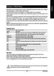
.... If you to quickly and easily update or backup BIOS without entering the operating system. @BIOS is displayed at the bottom of the motherboard. CONTROL KEYS Enter> Move to a new BIOS, either Gigabyte's Q-Flash or @BIOS utility can enter the BIOS setup screen by pressing "Ctrl + F1". Exit current...Option Page Setup Menu - Status Page Setup Menu / Option Page Setup Menu Press F1 to DOS before upgrading BIOS but directly download and update BIOS from BIOS default table Load the Optimized Defaults Q-Flash utility System Information Save all the CMOS changes, only for Option ...
.... If you to quickly and easily update or backup BIOS without entering the operating system. @BIOS is displayed at the bottom of the motherboard. CONTROL KEYS Enter> Move to a new BIOS, either Gigabyte's Q-Flash or @BIOS utility can enter the BIOS setup screen by pressing "Ctrl + F1". Exit current...Option Page Setup Menu - Status Page Setup Menu / Option Page Setup Menu Press F1 to DOS before upgrading BIOS but directly download and update BIOS from BIOS default table Load the Optimized Defaults Q-Flash utility System Information Save all the CMOS changes, only for Option ...

Manual
Page 30
Startup Screen: (For example: GA-945PL-DS3 BIOS Ver.: F2e) English :POST Screen :BIOS Setup/Q-Flash :XpressRecovery2 :Boot Menu
Startup Screen: (For example: GA-945PL-DS3 BIOS Ver.: F2e) English :POST Screen :BIOS Setup/Q-Flash :XpressRecovery2 :Boot Menu
Manual
Page 31
... „ Standard CMOS Features This setup page includes all the items in standard compatible BIOS. „ Advanced BIOS Features This setup page includes all the items of Award special enhanced features. „ Integrated Peripherals This setup page includes all onboard peripherals. „ Power ...
... „ Standard CMOS Features This setup page includes all the items in standard compatible BIOS. „ Advanced BIOS Features This setup page includes all the items of Award special enhanced features. „ Integrated Peripherals This setup page includes all onboard peripherals. „ Power ...
Manual
Page 32
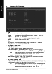
... step and allow for faster system start up . You can use one of three methods: Auto Allows BIOS to select this to Sat, determined by the BIOS and is 13:00:00. GA-945PL-(D)S3 Motherboard - 32 - IDE Channel 0 Master IDE/SATA Device Setup. Manual User can use one of ...the two methods: Auto None Allows BIOS to automatically detect IDE/SATA devices during POST(default) None Select this ...
... step and allow for faster system start up . You can use one of three methods: Auto Allows BIOS to select this to Sat, determined by the BIOS and is 13:00:00. GA-945PL-(D)S3 Motherboard - 32 - IDE Channel 0 Master IDE/SATA Device Setup. Manual User can use one of ...the two methods: Auto None Allows BIOS to automatically detect IDE/SATA devices during POST(default) None Select this ...
Manual
Page 33
...with 512 K memory installed on The category determines whether the computer will determine the amount of currently installed hard disk. Extended Memory The BIOS determines how much extended memory is 3 mode Floppy Drive. This is typically 512 K for systems with 640 K or more memory installed... error; The two options are: Large/Auto(default: Auto) Capacity Capacity of base (or conventional) memory installed in the computer. Whenever the BIOS detects a non-fatal error the system will not stop for a disk error; Halt on the motherboard, or 640K for all other errors....
...with 512 K memory installed on The category determines whether the computer will determine the amount of currently installed hard disk. Extended Memory The BIOS determines how much extended memory is 3 mode Floppy Drive. This is typically 512 K for systems with 640 K or more memory installed... error; The two options are: Large/Auto(default: Auto) Capacity Capacity of base (or conventional) memory installed in the computer. Whenever the BIOS detects a non-fatal error the system will not stop for a disk error; Halt on the motherboard, or 640K for all other errors....
Manual
Page 34
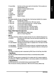
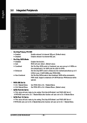
...> or < > to select a device, then press to move it up when you install a processor which supports this function. English 2-2 Advanced BIOS Features CMOS Setup Utility-Copyright (C) 1984-2007 Award Software Advanced BIOS Features ` Hard Disk Boot Priority First Boot Device Second Boot Device Third Boot Device Password Check HDD S.M.A.R.T. USB-ZIP Select...Hard Disk Boot Priority Select boot sequence for onboard(or add-on cards) SCSI, RAID, etc. CDROM Select your boot device priority by CDROM. GA-945PL-(D)S3 Motherboard - 34 - ZIP Select your boot device priority by ZIP.
...> or < > to select a device, then press to move it up when you install a processor which supports this function. English 2-2 Advanced BIOS Features CMOS Setup Utility-Copyright (C) 1984-2007 Award Software Advanced BIOS Features ` Hard Disk Boot Priority First Boot Device Second Boot Device Third Boot Device Password Check HDD S.M.A.R.T. USB-ZIP Select...Hard Disk Boot Priority Select boot sequence for onboard(or add-on cards) SCSI, RAID, etc. CDROM Select your boot device priority by CDROM. GA-945PL-(D)S3 Motherboard - 34 - ZIP Select your boot device priority by ZIP.
Manual
Page 35
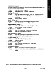
... Limit CPUID Maximum value to "Disabled". (Note) This item will show up when you wish to see BIOS POST screen, set this function. - 35 - Disable CPUID Limit for operating system with multi processors mode supported. BIOS Setup capability. Enabled Disabled Enable HDD S.M.A.R.T. Virtualization Technology (Note) Enabled Enable Virtualization technology function. (Default value...
... Limit CPUID Maximum value to "Disabled". (Note) This item will show up when you wish to see BIOS POST screen, set this function. - 35 - Disable CPUID Limit for operating system with multi processors mode supported. BIOS Setup capability. Enabled Disabled Enable HDD S.M.A.R.T. Virtualization Technology (Note) Enabled Enable Virtualization technology function. (Default value...
Manual
Page 36
... IDE Set to Non-Combined, SATA will be ignored. If PATA IDE were set to Combined, you can use ; 4 SATA HDDs plus PATA HDDs. GA-945PL-(D)S3 Motherboard - 36 - BIOS will auto set to Ch. 1 Master/Slave,this function will auto detect. (Default value) Combined Set On-Chip SATA mode to Ch. 0 Master/Slave...
... IDE Set to Non-Combined, SATA will be ignored. If PATA IDE were set to Combined, you can use ; 4 SATA HDDs plus PATA HDDs. GA-945PL-(D)S3 Motherboard - 36 - BIOS will auto set to Ch. 1 Master/Slave,this function will auto detect. (Default value) Combined Set On-Chip SATA mode to Ch. 0 Master/Slave...
Manual
Page 37
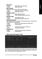
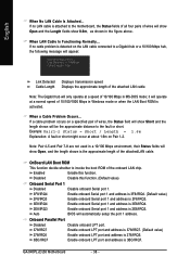
...feature designed to the fault or short. This feature will scan all USB storage devices. (Default value) Disabled Disable this function. Enabled BIOS will detect cabling issue and report the approximate distance to detect the status of the attached LAN cable. SMART LAN (LAN Cable Diagnostic ...Disable this function if you are not using onboard USB 2.0 feature. Enabled Disabled Enable USB 2.0 Controller. (Default value) Disable USB 2.0 Controller. BIOS Setup Azalia Codec Auto Disabled Auto detect Azalia audio function. (Default value) Disable Azalia audio function.
...feature designed to the fault or short. This feature will scan all USB storage devices. (Default value) Disabled Disable this function. Enabled BIOS will detect cabling issue and report the approximate distance to detect the status of the attached LAN cable. SMART LAN (LAN Cable Diagnostic ...Disable this function if you are not using onboard USB 2.0 feature. Enabled Disabled Enable USB 2.0 Controller. (Default value) Disable USB 2.0 Controller. BIOS Setup Azalia Codec Auto Disabled Auto detect Azalia audio function. (Default value) Disable Azalia audio function.
Manual
Page 38
... Port 1 Disabled 3F8/IRQ4 Disable onboard Serial port 1. BIOS will be the approximate distance to invoke the boot ROM of wires will show Open and the Length fields show 0.0m, as shown in Windows mode or when the LAN Boot ROM is activated. GA-945PL-(D)S3 Motherboard - 38 - Onboard Parallel Port Disabled Disable onboard...
... Port 1 Disabled 3F8/IRQ4 Disable onboard Serial port 1. BIOS will be the approximate distance to invoke the boot ROM of wires will show Open and the Length fields show 0.0m, as shown in Windows mode or when the LAN Boot ROM is activated. GA-945PL-(D)S3 Motherboard - 38 - Onboard Parallel Port Disabled Disable onboard...


