Manual
Page 4
... CPU 12 1-3-2 Installation of the Cooler 13 1-4 Installation of Memory 14 1-5 Installation of Expansion Cards 16 1-6 I/O Back Panel Introduction 17 1-7 Connectors Introduction 18 Chapter 2 BIOS Setup 29 The Main Menu (For example: GA-945PL-DS3 BIOS Ver.: F2e 30 2-1 Standard CMOS Features 32 2-2 Advanced BIOS Features 34 2-3 IntegratedPeripherals 36 2-4 Power Management Setup 39 2-5 PnP/PCI Configurations 41 2-6 PC Health Status 42 2-7 MB Intelligent Tweaker(M.I.T 44 2-8 Load Fail-Safe Defaults 47 2-9 Load Optimized Defaults 47 2-10 Set Supervisor/User Password...
... CPU 12 1-3-2 Installation of the Cooler 13 1-4 Installation of Memory 14 1-5 Installation of Expansion Cards 16 1-6 I/O Back Panel Introduction 17 1-7 Connectors Introduction 18 Chapter 2 BIOS Setup 29 The Main Menu (For example: GA-945PL-DS3 BIOS Ver.: F2e 30 2-1 Standard CMOS Features 32 2-2 Advanced BIOS Features 34 2-3 IntegratedPeripherals 36 2-4 Power Management Setup 39 2-5 PnP/PCI Configurations 41 2-6 PC Health Status 42 2-7 MB Intelligent Tweaker(M.I.T 44 2-8 Load Fail-Safe Defaults 47 2-9 Load Optimized Defaults 47 2-10 Set Supervisor/User Password...
Manual
Page 10
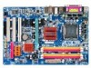
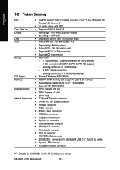
... 2 IDE devices - 4 SATA 3Gb/s connectors, allowing connection of 4 SATA 3Gb/s devices O.S Support Š Microsoft Windows 2000/XP/Vista Memory Š 4 DDRII DIMM memory slots (supports up to 2 GB memory) Š Supports dual channel DDRII 533(Note 1)/400 DIMMs Š Supports 1.8V DDRII DIMMs Expanstion Slots Š 1 PCI Express x16 slot Š 3 PCI Express x1 slots Š 3 PCI slots Internal Connectors Š 1 24-pin ATX power connector Š 1 4-pin ATX 12V power connector Š 1 floppy connector Š 1 IDE connector Š 4 SATA 3Gb/s connectors Š 1 CPU fan...
... 2 IDE devices - 4 SATA 3Gb/s connectors, allowing connection of 4 SATA 3Gb/s devices O.S Support Š Microsoft Windows 2000/XP/Vista Memory Š 4 DDRII DIMM memory slots (supports up to 2 GB memory) Š Supports dual channel DDRII 533(Note 1)/400 DIMMs Š Supports 1.8V DDRII DIMMs Expanstion Slots Š 1 PCI Express x16 slot Š 3 PCI Express x1 slots Š 3 PCI slots Internal Connectors Š 1 24-pin ATX power connector Š 1 4-pin ATX 12V power connector Š 1 floppy connector Š 1 IDE connector Š 4 SATA 3Gb/s connectors Š 1 CPU fan...
Manual
Page 11
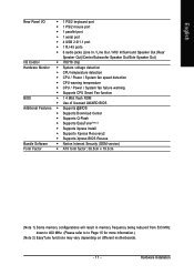
... mouse port Š 1 parallel port Š 1 serial port Š 4 USB 2.0/1.1 port Š 1 RJ-45 ports Š 6 audio jacks (Line In / Line Out / MIC In/Surround Speaker Out (Rear Speaker Out)/Center/Subwoofer Speaker Out/Side Speaker Out) I/O Control Š IT8718 chip Hardware Monitor Š System voltage detection Š CPU temperature detection Š CPU / Power / System fan speed detection Š CPU warning temperature Š CPU / Power / System fan failure warning Š Supports CPU Smart Fan function BIOS Š 1 4 Mbit flash ROM Š Use of licensed AWARD BIOS...
... mouse port Š 1 parallel port Š 1 serial port Š 4 USB 2.0/1.1 port Š 1 RJ-45 ports Š 6 audio jacks (Line In / Line Out / MIC In/Surround Speaker Out (Rear Speaker Out)/Center/Subwoofer Speaker Out/Side Speaker Out) I/O Control Š IT8718 chip Hardware Monitor Š System voltage detection Š CPU temperature detection Š CPU / Power / System fan speed detection Š CPU warning temperature Š CPU / Power / System fan failure warning Š Supports CPU Smart Fan function BIOS Š 1 4 Mbit flash ROM Š Use of licensed AWARD BIOS...
Manual
Page 13
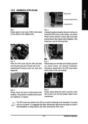
... CPU fan header located on the motherboard.Pressing down the push pins diagonally. If the push pin is inserted as a result of hardening of the heat paste. Fig. 6 Finally, please attach the power connector of motherboard after installing. To prevent such an occurrence, it is suggested that either thermal tape rather than heat paste be used for detailed installation instructions, please refer to the CPU...
... CPU fan header located on the motherboard.Pressing down the push pins diagonally. If the push pin is inserted as a result of hardening of the heat paste. Fig. 6 Finally, please attach the power connector of motherboard after installing. To prevent such an occurrence, it is suggested that either thermal tape rather than heat paste be used for detailed installation instructions, please refer to the CPU...
Manual
Page 15
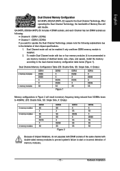
... memory frequency being reduced from 533MHz down to the dual channel memory configuration table below (Figure 1). GA-945PL-DS3/GA-945PL-S3 includes 4 DIMM sockets, and each Channel has two DIMM sockets as following: Channel 0 : DDRII1, DDRII2 Channel 1 : DDRII3, DDRII4 If you want to operate the Dual Channel Technology, please note the following explanations due to start or incorrect detection of Intel chipset specifications. 1. To enable Dual Channel mode with double-sided memory modules to prevent system's failure...
... memory frequency being reduced from 533MHz down to the dual channel memory configuration table below (Figure 1). GA-945PL-DS3/GA-945PL-S3 includes 4 DIMM sockets, and each Channel has two DIMM sockets as following: Channel 0 : DDRII1, DDRII2 Channel 1 : DDRII3, DDRII4 If you want to operate the Dual Channel Technology, please note the following explanations due to start or incorrect detection of Intel chipset specifications. 1. To enable Dual Channel mode with double-sided memory modules to prevent system's failure...
Manual
Page 18
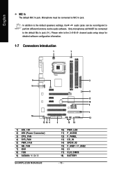
... In jack ( ). channel audio setup steps for detailed software configuration information. 1-7 Connectors Introduction 1 3 6 11 16 13 14 4 1) ATX_12V 2) ATX (Power Connector) 3) CPU_FAN 4) SYS_FAN 5) PWR_FAN 6) NB_FAN 7) IDE1 8) FDD 9) SATAII0 / 1 / 2 / 3 GA-945PL-(D)S3 Motherboard 2 5 17 18 9 7 12 8 15 10 10) PWR_LED 11) F_AUDIO 12) F_PANEL 13) CD_IN 14) SPDIF_IO 15) F_USB1 / F_USB2 16) CI 17) CLR_CMOS 18) BATTERY - 18 - Only microphones still MUST be connected to the 2-/4-/6-/8-
... In jack ( ). channel audio setup steps for detailed software configuration information. 1-7 Connectors Introduction 1 3 6 11 16 13 14 4 1) ATX_12V 2) ATX (Power Connector) 3) CPU_FAN 4) SYS_FAN 5) PWR_FAN 6) NB_FAN 7) IDE1 8) FDD 9) SATAII0 / 1 / 2 / 3 GA-945PL-(D)S3 Motherboard 2 5 17 18 9 7 12 8 15 10 10) PWR_LED 11) F_AUDIO 12) F_PANEL 13) CD_IN 14) SPDIF_IO 15) F_USB1 / F_USB2 16) CI 17) CLR_CMOS 18) BATTERY - 18 - Only microphones still MUST be connected to the 2-/4-/6-/8-
Manual
Page 20
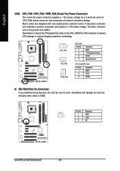
...) If you installed wrong direction, the chip fan will damage the chip fan. (Usually black cable is the ground wire (GND). English 3/4/5) CPU_FAN / SYS_FAN / PWR_FAN (Cooler Fan Power Connector) The cooler fan power connector supplies a +12V power voltage via a 3-pin/4-pin (only for CPU_FAN) power connector and possesses a foolproof connection design. The black connector wire is GND) Pin No. Definition 1 1 GND 2 +12V 3 NC GA-945PL-(D)S3 Motherboard - 20 - Sometimes will not work. Most coolers are designed with color-coded power connector wires. A red power connector wire...
...) If you installed wrong direction, the chip fan will damage the chip fan. (Usually black cable is the ground wire (GND). English 3/4/5) CPU_FAN / SYS_FAN / PWR_FAN (Cooler Fan Power Connector) The cooler fan power connector supplies a +12V power voltage via a 3-pin/4-pin (only for CPU_FAN) power connector and possesses a foolproof connection design. The black connector wire is GND) Pin No. Definition 1 1 GND 2 +12V 3 NC GA-945PL-(D)S3 Motherboard - 20 - Sometimes will not work. Most coolers are designed with color-coded power connector wires. A red power connector wire...
Manual
Page 21
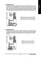
... connector is used to connect the FDD cable while the other as Slave (for information on one IDE cable, and the single IDE cable can then connect to the instructions located on the IDE device). Before attaching the IDE cable, please take note of the cable connects to the computer via an IDE connector. If you wish to connect two IDE devices, please set the jumper on settings, please refer to two IDE devices (hard drive or optical drive). Hardware Installation...
... connector is used to connect the FDD cable while the other as Slave (for information on one IDE cable, and the single IDE cable can then connect to the instructions located on the IDE device). Before attaching the IDE cable, please take note of the cable connects to the computer via an IDE connector. If you wish to connect two IDE devices, please set the jumper on settings, please refer to two IDE devices (hard drive or optical drive). Hardware Installation...
Manual
Page 22
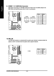
...- GA-945PL-(D)S3 Motherboard - 22 - English 9) SATAII0 / 1 / 2 / 3 (SATA 3Gb/s Connectors) SATA 3Gb/s can provide up to work properly. Please refer to the BIOS setting for the SATA 3Gb/s and install the proper driver in order to 300 MB/s transfer rate. SATAII0 7 17 SATAII2 1 1 71 7 SATAII1 SATAII3 Pin No. 1 2 3 4 5 6 7 Definition GND TXP TXN GND RXN RXP GND 10) PWR_LED The PWR_LED connector is connected with the system power...
...- GA-945PL-(D)S3 Motherboard - 22 - English 9) SATAII0 / 1 / 2 / 3 (SATA 3Gb/s Connectors) SATA 3Gb/s can provide up to work properly. Please refer to the BIOS setting for the SATA 3Gb/s and install the proper driver in order to 300 MB/s transfer rate. SATAII0 7 17 SATAII2 1 1 71 7 SATAII1 SATAII3 Pin No. 1 2 3 4 5 6 7 Definition GND TXP TXN GND RXN RXP GND 10) PWR_LED The PWR_LED connector is connected with the system power...
Manual
Page 24
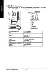
...LED, PC speaker, reset switch and power switch etc of your chassis front panel to the F_PANEL connector according to the pin assignment below. Pin 3: NC Pin 4: Data(-) Open: Normal Close: Reset Hardware System Open: Normal Close: Power On/Off Pin 1: LED anode(+) Pin 2: LED cathode(-) NC GA-945PL-(D)S3 Motherboard - 24 - RESRES+ NC HD (IDE Hard Disk Active LED) (Blue) SPEAK (Speaker Connector) (Amber) RES (Reset Switch) (Green) PW (Power Switch) (Red) MSG (Message LED/Power/Sleep LED) (Yellow) NC ( Purple) Reset Switch IDE Hard Disk Active LED Pin 1: LED anode(+) Pin 2: LED cathode(-) Pin...
...LED, PC speaker, reset switch and power switch etc of your chassis front panel to the F_PANEL connector according to the pin assignment below. Pin 3: NC Pin 4: Data(-) Open: Normal Close: Reset Hardware System Open: Normal Close: Power On/Off Pin 1: LED anode(+) Pin 2: LED cathode(-) NC GA-945PL-(D)S3 Motherboard - 24 - RESRES+ NC HD (IDE Hard Disk Active LED) (Blue) SPEAK (Speaker Connector) (Amber) RES (Reset Switch) (Green) PW (Power Switch) (Red) MSG (Message LED/Power/Sleep LED) (Yellow) NC ( Purple) Reset Switch IDE Hard Disk Active LED Pin 1: LED anode(+) Pin 2: LED cathode(-) Pin...
Manual
Page 32
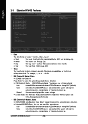
... detect IDE/SATA devices during POST(default) Select this option for the hard drive. You can use one of the two methods: Auto None Allows BIOS to select this if no IDE/SATA devices are used and the system will skip the automatic detection step and allow for automatic device detection. GA-945PL-(D)S3 Motherboard - 32 - Through Dec. IDE Channel 0 Master IDE/SATA Device Setup. The four options are: CHS/LBA/Large/Auto(default:Auto) IDE Channel 2/3 Master, Slave IDE/SATA HDD Auto-Detection Press "Enter" to...
... detect IDE/SATA devices during POST(default) Select this option for the hard drive. You can use one of the two methods: Auto None Allows BIOS to select this if no IDE/SATA devices are used and the system will skip the automatic detection step and allow for automatic device detection. GA-945PL-(D)S3 Motherboard - 32 - Through Dec. IDE Channel 0 Master IDE/SATA Device Setup. The four options are: CHS/LBA/Large/Auto(default:Auto) IDE Channel 2/3 Master, Slave IDE/SATA HDD Auto-Detection Press "Enter" to...
Manual
Page 37
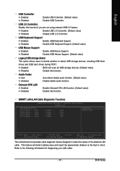
... drives during POST. SMART LAN (LAN Cable Diagnostic Function) CMOS Setup Utility-Copyright (C) 1984-2007 Award Software SMART LAN Start detecting at Port..... This feature will scan all USB storage devices. (Default value) Disabled Disable this function. USB 2.0 Controller Disable this function if you are not using onboard USB 2.0 feature. Enabled Disabled Enable USB 2.0 Controller. (Default value) Disable USB 2.0 Controller. USB Keyboard Support Enabled Enable USB Keyboard Support. Disabled Disable USB Mouse Support. (Default value) Legacy USB storage detect This option...
... drives during POST. SMART LAN (LAN Cable Diagnostic Function) CMOS Setup Utility-Copyright (C) 1984-2007 Award Software SMART LAN Start detecting at Port..... This feature will scan all USB storage devices. (Default value) Disabled Disable this function. USB 2.0 Controller Disable this function if you are not using onboard USB 2.0 feature. Enabled Disabled Enable USB 2.0 Controller. (Default value) Disable USB 2.0 Controller. USB Keyboard Support Enabled Enable USB Keyboard Support. Disabled Disable USB Mouse Support. (Default value) Legacy USB storage detect This option...
Manual
Page 42
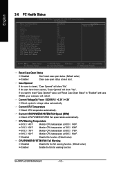
.... Monitor CPU temperature at 70oC / 158oF. GA-945PL-(D)S3 Motherboard - 42 - Current Voltage(V) Vcore / DDR18V / +3.3V / +12V Detect system's voltage status automatically. Disable this function. (Default value) CPU/POWER/SYSTEM FAN Fail Warning Disabled Enabled Disable the fan fail warning function. (Default value) Enable the fan fail warning function. Monitor CPU temperature at next boot. If you want to reset "Case Opened" value, set "Reset Case Open Status" to "Enabled" and save CMOS, your computer will show "Yes". Current CPU/POWER/SYSTEM FAN Speed (RPM) Detect CPU/POWER...
.... Monitor CPU temperature at 70oC / 158oF. GA-945PL-(D)S3 Motherboard - 42 - Current Voltage(V) Vcore / DDR18V / +3.3V / +12V Detect system's voltage status automatically. Disable this function. (Default value) CPU/POWER/SYSTEM FAN Fail Warning Disabled Enabled Disable the fan fail warning function. (Default value) Enable the fan fail warning function. Monitor CPU temperature at next boot. If you want to reset "Case Opened" value, set "Reset Case Open Status" to "Enabled" and save CMOS, your computer will show "Yes". Current CPU/POWER/SYSTEM FAN Speed (RPM) Detect CPU/POWER...
Manual
Page 48
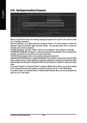
...USER PASSWORD. GA-945PL-(D)S3 Motherboard - 48 - A message "PASSWORD DISABLED" will appear to abort the selection and not enter a password. When disabled, anyone may also press to confirm the password being disabled. English 2-10 Set Supervisor/User Password CMOS Setup Utility-Copyright (C) 1984-2007 Award Software ` Standard CMOS Features ` Advanced BIOS Features ` Integrated Peripherals ` Power Management Setup ` PnP/PCI ConfigurationEsnter Password: ` PC Health Status ` MB Intelligent Tweaker(M.I.T.) Load Fail-Safe Defaults Load Optimized Defaults Set Supervisor Password Set User...
...USER PASSWORD. GA-945PL-(D)S3 Motherboard - 48 - A message "PASSWORD DISABLED" will appear to abort the selection and not enter a password. When disabled, anyone may also press to confirm the password being disabled. English 2-10 Set Supervisor/User Password CMOS Setup Utility-Copyright (C) 1984-2007 Award Software ` Standard CMOS Features ` Advanced BIOS Features ` Integrated Peripherals ` Power Management Setup ` PnP/PCI ConfigurationEsnter Password: ` PC Health Status ` MB Intelligent Tweaker(M.I.T.) Load Fail-Safe Defaults Load Optimized Defaults Set Supervisor Password Set User...
Manual
Page 49
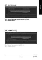
... CMOS Type "Y" will quit the Setup Utility and save the user setup value to RTC CMOS. English 2-11 Save & Exit Setup CMOS Setup Utility-Copyright (C) 1984-2007 Award Software ` Standard CMOS Features Load Fail-Safe Defaults ` Advanced BIOS Features Load Optimized Defaults ` Integrated Peripherals Set Supervisor Password ` Power Management Setup Save to CMOS and EXIT (SYe/tNU)?seYr Password ` PnP/PCI Configurations Save & Exit Setup ` PC Health Status Exit Without Saving ` MB Intelligent Tweaker(M.I .T.) ESC: Quit F8: Q-Flash Load Fail-Safe Defaults Load Optimized Defaults Set...
... CMOS Type "Y" will quit the Setup Utility and save the user setup value to RTC CMOS. English 2-11 Save & Exit Setup CMOS Setup Utility-Copyright (C) 1984-2007 Award Software ` Standard CMOS Features Load Fail-Safe Defaults ` Advanced BIOS Features Load Optimized Defaults ` Integrated Peripherals Set Supervisor Password ` Power Management Setup Save to CMOS and EXIT (SYe/tNU)?seYr Password ` PnP/PCI Configurations Save & Exit Setup ` PC Health Status Exit Without Saving ` MB Intelligent Tweaker(M.I .T.) ESC: Quit F8: Q-Flash Load Fail-Safe Defaults Load Optimized Defaults Set...
Manual
Page 51
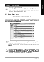
... double click the CD-ROM device icon in Windows XP. English Chapter 3 Install Drivers Pictures below are shown in "My computer", and execute the Run.exe. 3-1 Install Chipset Drivers After insert the driver CD, "Xpress Install" will auto start and show a question mark "?" After restarting your CD-ROM drive, the driver CD-title will scan automatically the system and then list all items defaulted. Please pick the...
... double click the CD-ROM device icon in Windows XP. English Chapter 3 Install Drivers Pictures below are shown in "My computer", and execute the Run.exe. 3-1 Install Chipset Drivers After insert the driver CD, "Xpress Install" will auto start and show a question mark "?" After restarting your CD-ROM drive, the driver CD-title will scan automatically the system and then list all items defaulted. Please pick the...
Manual
Page 56
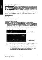
... your hard disk. Boot from CD/DVD:" will appear in the bottom left corner of the screen. It is recommended that Xpress Recovery2 be made by pressing the F9 key: Steps: After entering BIOS Setup, go to Advanced BIOS Feature and set to use the Xpress Recovery2 Initial access by booting from the CD-ROM, you can simply press F9 during system power-on PATA and SATA IDE controllers. Supporting...
... your hard disk. Boot from CD/DVD:" will appear in the bottom left corner of the screen. It is recommended that Xpress Recovery2 be made by pressing the F9 key: Steps: After entering BIOS Setup, go to Advanced BIOS Feature and set to use the Xpress Recovery2 Initial access by booting from the CD-ROM, you can simply press F9 during system power-on PATA and SATA IDE controllers. Supporting...
Manual
Page 58
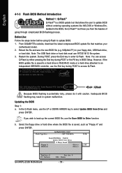
... BIOS Setup. During POST, press the End key to select Update BIOS from Drive and press ENTER. However, if the BIOS update file is a BIOS update tool that matches your floppy disk, USB flash drive, or hard disk. Inadequate BIOS flashing may result in the BIOS, the Q-FlashTM tool frees you wish to back up the current BIOS file, use the Save BIOS to access Q-Flash. If you from Drive Sa0vefilBeI(Os)SfotounDdrive EnteFr l:oRppuyn A :Move ESC:Reset :Power Off HDD 0-0 Total size : 0 F5 : Refresh GA-945PL-(D)S3 Motherboard Free size...
... BIOS Setup. During POST, press the End key to select Update BIOS from Drive and press ENTER. However, if the BIOS update file is a BIOS update tool that matches your floppy disk, USB flash drive, or hard disk. Inadequate BIOS flashing may result in the BIOS, the Q-FlashTM tool frees you wish to back up the current BIOS file, use the Save BIOS to access Q-Flash. If you from Drive Sa0vefilBeI(Os)SfotounDdrive EnteFr l:oRppuyn A :Move ESC:Reset :Power Off HDD 0-0 Total size : 0 F5 : Refresh GA-945PL-(D)S3 Motherboard Free size...
Manual
Page 60
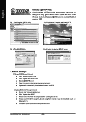
Installing the @BIOS utility Fig 2. Update BIOS through Internet: a. Select @BIOSTM sever d. Select the exact model name on your motherboard e. GA-945PL-(D)S3 Motherboard - 60 - Fig 1. Click "Internet Update" icon b. Do not click "Internet Update" icon b. Please select "All Files" in dialog box while opening the old file. e. Methods and steps: I. Click "Update New BIOS" icon c. Please search for BIOS unzip file, downloading from internet or any other methods (such as...
Installing the @BIOS utility Fig 2. Update BIOS through Internet: a. Select @BIOSTM sever d. Select the exact model name on your motherboard e. GA-945PL-(D)S3 Motherboard - 60 - Fig 1. Click "Internet Update" icon b. Do not click "Internet Update" icon b. Please select "All Files" in dialog box while opening the old file. e. Methods and steps: I. Click "Update New BIOS" icon c. Please search for BIOS unzip file, downloading from internet or any other methods (such as...
Manual
Page 67
... Del to case. If not, please change another speaker with an internal amplifier. Disconnect the power cord from computer after turning up . Answer: The beep codes below : Steps: 1. AWARD BIOS Beep Codes 1 short: System boots successfully 2 short: CMOS setting error 1 long 1 short: DRAM or M/B error 1 long 2 short: Monitor or display card error 1 long 3 short: Keyboard error 1 long 9 short: BIOS ROM error Continuous long beeps: DRAM error Continuous short beeps: Power error - 67 - Question 5: Sometimes I hear different continuous beeps from MB. 3. Connect power cord to...
... Del to case. If not, please change another speaker with an internal amplifier. Disconnect the power cord from computer after turning up . Answer: The beep codes below : Steps: 1. AWARD BIOS Beep Codes 1 short: System boots successfully 2 short: CMOS setting error 1 long 1 short: DRAM or M/B error 1 long 2 short: Monitor or display card error 1 long 3 short: Keyboard error 1 long 9 short: BIOS ROM error Continuous long beeps: DRAM error Continuous short beeps: Power error - 67 - Question 5: Sometimes I hear different continuous beeps from MB. 3. Connect power cord to...


