Manual
Page 4
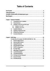
Table of Contents ItemChecklist ...6 OptionalAccessories ...6 GA-945PL-DS3/GA-945PL-S3 Motherboard Layout 7 Block Diagram ...8 Chapter 1 Hardware Installation 9 1-1 Considerations Prior to Installation 9 1-2 Feature Summary 10 1-3 Installation of the CPU and CPU Cooler 12 1-3-1 Installation of the CPU 12 1-3-2 Installation of the Cooler 13 1-4 Installation of Memory 14 1-5 Installation of Expansion Cards 16 1-6 I/O Back Panel Introduction 17 1-7 Connectors Introduction 18...
Table of Contents ItemChecklist ...6 OptionalAccessories ...6 GA-945PL-DS3/GA-945PL-S3 Motherboard Layout 7 Block Diagram ...8 Chapter 1 Hardware Installation 9 1-1 Considerations Prior to Installation 9 1-2 Feature Summary 10 1-3 Installation of the CPU and CPU Cooler 12 1-3-1 Installation of the CPU 12 1-3-2 Installation of the Cooler 13 1-4 Installation of Memory 14 1-5 Installation of Expansion Cards 16 1-6 I/O Back Panel Introduction 17 1-7 Connectors Introduction 18...
Manual
Page 8
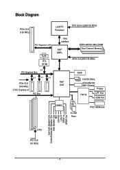
Block Diagram PCIe CLK (100 MHz) LGA775 Processor CPU CLK+/-(200/133 MHz) PCI Express x16 RJ45 RTL 8111B x1 PCI Express Bus x1 x1 x1 PCIe CLK (100 MHz) 3 PCI Express x1 PCI Bus Host Interface Intel® 945PL DDRII 400/533 MHz DIMM Dual Channel Memory MCH CLK(200/133 MHz) BIOS 4 SATA 3Gb/s Intel® ATA33/66/100 ICH7 IDE1 Channel Floppy IT8718 LPT Port COM Port CODEC 8 USB Ports PS/2 KB/Mouse Surround Speaker Out Center/Subwoofer Speaker Out Side Speaker Out MIC Line-Out Line-In SPDIF In SPDIF Out 3 PCI PCI CLK (33 MHz) - 8 -
Block Diagram PCIe CLK (100 MHz) LGA775 Processor CPU CLK+/-(200/133 MHz) PCI Express x16 RJ45 RTL 8111B x1 PCI Express Bus x1 x1 x1 PCIe CLK (100 MHz) 3 PCI Express x1 PCI Bus Host Interface Intel® 945PL DDRII 400/533 MHz DIMM Dual Channel Memory MCH CLK(200/133 MHz) BIOS 4 SATA 3Gb/s Intel® ATA33/66/100 ICH7 IDE1 Channel Floppy IT8718 LPT Port COM Port CODEC 8 USB Ports PS/2 KB/Mouse Surround Speaker Out Center/Subwoofer Speaker Out Side Speaker Out MIC Line-Out Line-In SPDIF In SPDIF Out 3 PCI PCI CLK (33 MHz) - 8 -
Manual
Page 9
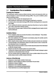
...components, please have a problem related to the use of uncertified components. 5. Turning on the motherboard. Damage due to be an unofficial Gigabyte product. - 9 - Damage due to system components as well as a result of violating the conditions recommended in contact with the ... or metal components placed on an uneven surface. 7. Thus, prior to wear an electrostatic discharge (ESD) cuff when handling electronic components (CPU, RAM). 4. Before using the product, please verify that the power supply is best to installation, please follow the instructions below: 1. ...
...components, please have a problem related to the use of uncertified components. 5. Turning on the motherboard. Damage due to be an unofficial Gigabyte product. - 9 - Damage due to system components as well as a result of violating the conditions recommended in contact with the ... or metal components placed on an uneven surface. 7. Thus, prior to wear an electrostatic discharge (ESD) cuff when handling electronic components (CPU, RAM). 4. Before using the product, please verify that the power supply is best to installation, please follow the instructions below: 1. ...
Manual
Page 10
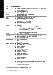
... 24-pin ATX power connector Š 1 4-pin ATX 12V power connector Š 1 floppy connector Š 1 IDE connector Š 4 SATA 3Gb/s connectors Š 1 CPU fan connector Š 1 system fan connector Š 1 power fan connector Š 1 northbridge fan connector Š 1 front panel connector Š 1 front audio connector Š... Š 2 USB 2.0/1.1 connectors for additional 4 USB 2.0/1.1 ports by cables Š 1 power LED connector Š 1 Chassis Intrusion connector "*" Only the GA-945PL-DS3 adopts All-Solid Capacitor design. GA-945PL-(D)S3 Motherboard - 10 -
... 24-pin ATX power connector Š 1 4-pin ATX 12V power connector Š 1 floppy connector Š 1 IDE connector Š 4 SATA 3Gb/s connectors Š 1 CPU fan connector Š 1 system fan connector Š 1 power fan connector Š 1 northbridge fan connector Š 1 front panel connector Š 1 front audio connector Š... Š 2 USB 2.0/1.1 connectors for additional 4 USB 2.0/1.1 ports by cables Š 1 power LED connector Š 1 Chassis Intrusion connector "*" Only the GA-945PL-DS3 adopts All-Solid Capacitor design. GA-945PL-(D)S3 Motherboard - 10 -
Manual
Page 11
... Out/Side Speaker Out) I/O Control Š IT8718 chip Hardware Monitor Š System voltage detection Š CPU temperature detection Š CPU / Power / System fan speed detection Š CPU warning temperature Š CPU / Power / System fan failure warning Š Supports CPU Smart Fan function BIOS Š 1 4 Mbit flash ROM Š Use of licensed AWARD BIOS Additional Features...
... Out/Side Speaker Out) I/O Control Š IT8718 chip Hardware Monitor Š System voltage detection Š CPU temperature detection Š CPU / Power / System fan speed detection Š CPU warning temperature Š CPU / Power / System fan failure warning Š Supports CPU Smart Fan function BIOS Š 1 4 Mbit flash ROM Š Use of licensed AWARD BIOS Additional Features...
Manual
Page 12
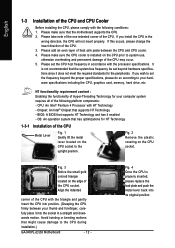
... in a straight and downwards motion. English 1-3 Installation of the CPU and CPU Cooler Before installing the CPU, please comply with HT Technology - Please set beyond the proper specifications, please do so according to the CPU during installation.) GA-945PL-(D)S3 Motherboard - 12 - Align the indented corner of the CPU with the processor specifications. Avoid twisting or bending motions...
... in a straight and downwards motion. English 1-3 Installation of the CPU and CPU Cooler Before installing the CPU, please comply with HT Technology - Please set beyond the proper specifications, please do so according to the CPU during installation.) GA-945PL-(D)S3 Motherboard - 12 - Align the indented corner of the CPU with the processor specifications. Avoid twisting or bending motions...
Manual
Page 13
...picture, the installation is inserted as a result of hardening of motherboard after installing. Fig. 4 Please make sure the push pins aim to the CPU cooler installation section of the user manual) Fig. 5 Please check the back of the heat paste. To prevent such an occurrence, it is only...installation. (This instruction is suggested that either thermal tape rather than heat paste be used for Intel boxed fan) Fig. 3 Place the CPU cooler atop the CPU and make sure the Male and Female push pin are joined closely. (for detailed installation instructions, please refer to the pin hole on...
...picture, the installation is inserted as a result of hardening of motherboard after installing. Fig. 4 Please make sure the push pins aim to the CPU cooler installation section of the user manual) Fig. 5 Please check the back of the heat paste. To prevent such an occurrence, it is only...installation. (This instruction is suggested that either thermal tape rather than heat paste be used for Intel boxed fan) Fig. 3 Place the CPU cooler atop the CPU and make sure the Male and Female push pin are joined closely. (for detailed installation instructions, please refer to the pin hole on...

Manual
Page 19
... unstable system or a system that is recommended that a power supply that all the components on the motherboard and connect tightly. It is unable to the CPU.
... unstable system or a system that is recommended that a power supply that all the components on the motherboard and connect tightly. It is unable to the CPU.
Manual
Page 20
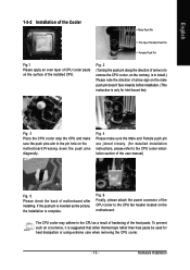
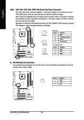
Most coolers are designed with color-coded power connector wires. Sometimes will not work. Remember to connect the CPU/system fan cable to the CPU_FAN/SYS_FAN connector to prevent CPU damage or system hanging caused by overheating. 1 CPU_FAN 1 SYS_FAN 1 PWR_FAN CPU_FAN: Pin No. 1 2 3 4 Definition GND +12V/Speed Control Sense Speed Control SYS_FAN/... cooler fan power connector supplies a +12V power voltage via a 3-pin/4-pin (only for CPU_FAN) power connector and possesses a foolproof connection design. Definition 1 1 GND 2 +12V 3 NC GA-945PL-(D)S3 Motherboard - 20 -
Most coolers are designed with color-coded power connector wires. Sometimes will not work. Remember to connect the CPU/system fan cable to the CPU_FAN/SYS_FAN connector to prevent CPU damage or system hanging caused by overheating. 1 CPU_FAN 1 SYS_FAN 1 PWR_FAN CPU_FAN: Pin No. 1 2 3 4 Definition GND +12V/Speed Control Sense Speed Control SYS_FAN/... cooler fan power connector supplies a +12V power voltage via a 3-pin/4-pin (only for CPU_FAN) power connector and possesses a foolproof connection design. Definition 1 1 GND 2 +12V 3 NC GA-945PL-(D)S3 Motherboard - 20 -
Manual
Page 31
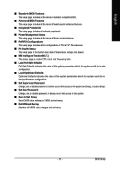
.... „ PC Health Status This setup page is the System auto detect Temperature, voltage, fan, speed. „ MB Intelligent Tweaker(M.I.T.) This setup page is control CPU clock and frequency ratio. „ Load Fail-Safe Defaults Fail-Safe Defaults indicates the value of the system parameters which the system would be in...
.... „ PC Health Status This setup page is the System auto detect Temperature, voltage, fan, speed. „ MB Intelligent Tweaker(M.I.T.) This setup page is control CPU clock and frequency ratio. „ Load Fail-Safe Defaults Fail-Safe Defaults indicates the value of the system parameters which the system would be in...
Manual
Page 33
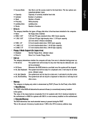
...-only which is determined by POST (Power On Self Test) of the base memory is the amount of base (or conventional) memory installed in the CPU's memory address map. - 33 - None 360K, 5.25" No floppy drive installed 5.25 inch PC-type standard drive; 360 K byte capacity. 1.2M, 5.25" 5.25 inch AT...
...-only which is determined by POST (Power On Self Test) of the base memory is the amount of base (or conventional) memory installed in the CPU's memory address map. - 33 - None 360K, 5.25" No floppy drive installed 5.25 inch PC-type standard drive; 360 K byte capacity. 1.2M, 5.25" 5.25 inch AT...
Manual
Page 34
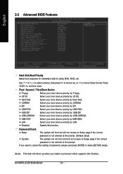
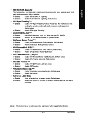
... ENTER to make [SETUP] empty. (Note) This item will not access to 3 (Note) No-Execute Memory Protect (Note) CPU Enhanced Halt (C1E) (Note) CPU Thermal Monitor 2(TM2) (Note) CPU EIST Function (Note) Virtualization Technology (Note) Full Screen LOGO Show [Press Enter] [Floppy] [Hard Disk] [CDROM] [Setup]...by Hard Disk. LAN Select your boot device priority by LAN. ZIP Select your boot device priority by ZIP. GA-945PL-(D)S3 Motherboard - 34 - Capability CPU Hyper-Threading (Note) Limit CPUID Max. Disabled Disable this function. Password Check Setup The system will boot but...
... ENTER to make [SETUP] empty. (Note) This item will not access to 3 (Note) No-Execute Memory Protect (Note) CPU Enhanced Halt (C1E) (Note) CPU Thermal Monitor 2(TM2) (Note) CPU EIST Function (Note) Virtualization Technology (Note) Full Screen LOGO Show [Press Enter] [Floppy] [Hard Disk] [CDROM] [Setup]...by Hard Disk. LAN Select your boot device priority by LAN. ZIP Select your boot device priority by ZIP. GA-945PL-(D)S3 Motherboard - 34 - Capability CPU Hyper-Threading (Note) Limit CPUID Max. Disabled Disable this function. Password Check Setup The system will boot but...
Manual
Page 35
... function. (Default value) Disable EIST function. BIOS Setup Disabled (Default value) Disable CPU Hyper Threading. CPU Thermal Monitor 2 (TM2) (Note) Enabled Disabled Enable CPU Thermal Monitor 2 (TM2) function. (Default value) Disable CPU Thermal Monitor 2 (TM2) function. Capability This feature allows your hard disk to report read/write errors and to 3 when use older OS...
... function. (Default value) Disable EIST function. BIOS Setup Disabled (Default value) Disable CPU Hyper Threading. CPU Thermal Monitor 2 (TM2) (Note) Enabled Disabled Enable CPU Thermal Monitor 2 (TM2) function. (Default value) Disable CPU Thermal Monitor 2 (TM2) function. Capability This feature allows your hard disk to report read/write errors and to 3 when use older OS...
Manual
Page 42
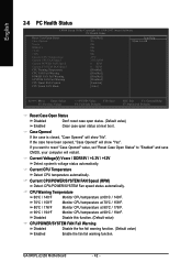
..., "Case Opened" will show "Yes". Current CPU/POWER/SYSTEM FAN Speed (RPM) Detect CPU/POWER/SYSTEM Fan speed status automatically. Monitor CPU temperature at 70oC / 158oF. CPU Warning Temperature 60oC / 140oF Monitor CPU temperature at 60oC / 140oF. 70oC / 158oF 80oC / 176oF 90oC / 194oF Disabled Monitor CPU temperature at 90oC / 194oF. GA-945PL-(D)S3 Motherboard - 42 - If the case have...
..., "Case Opened" will show "Yes". Current CPU/POWER/SYSTEM FAN Speed (RPM) Detect CPU/POWER/SYSTEM Fan speed status automatically. Monitor CPU temperature at 70oC / 158oF. CPU Warning Temperature 60oC / 140oF Monitor CPU temperature at 60oC / 140oF. 70oC / 158oF 80oC / 176oF 90oC / 194oF Disabled Monitor CPU temperature at 90oC / 194oF. GA-945PL-(D)S3 Motherboard - 42 - If the case have...
Manual
Page 43
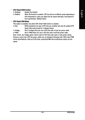
...BIOS autodetects the type of CPU fan you installed and sets the optimal CPU Smart FAN control mode for CPU fans with Easy Tune based on their requirements. (Default Value) CPU Smart FAN Mode This option is available only when CPU Smart FAN Control is enabled, CPU fan will not effectively reduce... When this function. Note: In fact, the Voltage option can adjust the fan speed with 3-pin or 4-pin power cables. With such CPU fans, selecting PWM will run at different speed depending on CPU temperature. Users can be used for it. (Default Value) Voltage Set to PWM when you use...
...BIOS autodetects the type of CPU fan you installed and sets the optimal CPU Smart FAN control mode for CPU fans with Easy Tune based on their requirements. (Default Value) CPU Smart FAN Mode This option is available only when CPU Smart FAN Control is enabled, CPU fan will not effectively reduce... When this function. Note: In fact, the Voltage option can adjust the fan speed with 3-pin or 4-pin power cables. With such CPU fans, selecting PWM will run at different speed depending on CPU temperature. Users can be used for it. (Default Value) Voltage Set to PWM when you use...
Manual
Page 44
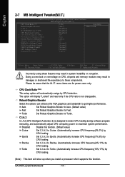
... Tweaker(M.I.T.) CMOS Setup Utility-Copyright (C) 1984-2007 Award Software MB Intelligent Tweaker(M.I.T.) CPU Clock Ratio (Note) Robust Graphics Booster C.I.A. 2 O.C FSB1066 Core. 2 CPU CPU Host Clock Control x CPU Host Frequency (Mhz) x PCI Experss Frequency (Mhz) System Memory Multiplier Memory ...GA-945PL-(D)S3 Motherboard - 44 - Set C.I.A.2 to Turbo. (Automatically increase CPU frequency(15%,17%) by CPU loading. (Note) This item will display "Locked" and read only if the CPU ratio is designed to detect CPU loading during software program executing, and automatically adjust CPU...
... Tweaker(M.I.T.) CMOS Setup Utility-Copyright (C) 1984-2007 Award Software MB Intelligent Tweaker(M.I.T.) CPU Clock Ratio (Note) Robust Graphics Booster C.I.A. 2 O.C FSB1066 Core. 2 CPU CPU Host Clock Control x CPU Host Frequency (Mhz) x PCI Experss Frequency (Mhz) System Memory Multiplier Memory ...GA-945PL-(D)S3 Motherboard - 44 - Set C.I.A.2 to Turbo. (Automatically increase CPU frequency(15%,17%) by CPU loading. (Note) This item will display "Locked" and read only if the CPU ratio is designed to detect CPU loading during software program executing, and automatically adjust CPU...
Manual
Page 45
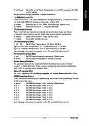
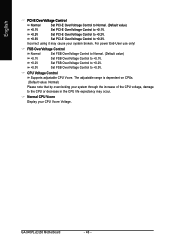
..., set memory frequency by DRAM SPD data). Memory Frequency (Mhz) The values depend on the CPU FSB. If you must install DDRII 533 memory module(s) and a CoreTM 2 CPU. Incorrect using it may cause your system broken. PCI Express Frequency (Mhz) Auto Set PCI ... DIMM OverVoltage Control Please note that if your system is highly dependent on system components. Disabled Disable CPU Host Clock Control. (Default value) Enabled Enable CPU Host Clock Control. Incorrect using it may cause your system broken. BIOS Setup for automatic system restart...
..., set memory frequency by DRAM SPD data). Memory Frequency (Mhz) The values depend on the CPU FSB. If you must install DDRII 533 memory module(s) and a CoreTM 2 CPU. Incorrect using it may cause your system broken. PCI Express Frequency (Mhz) Auto Set PCI ... DIMM OverVoltage Control Please note that if your system is highly dependent on system components. Disabled Disable CPU Host Clock Control. (Default value) Enabled Enable CPU Host Clock Control. Incorrect using it may cause your system broken. BIOS Setup for automatic system restart...
Manual
Page 46
... Supports adjustable CPU Vcore. Normal CPU Vcore Display your system broken. GA-945PL-(D)S3 Motherboard - 46 - Incorrect using it may occur. English PCI-E OverVoltage Control Normal Set PCI-E OverVoltrage Control to Normal. (Default value) +0.1V +0....Default value: Normal) Please note that by overclocking your system through the increase of the CPU voltage, damage to +0.3V. Set FSB OverVoltage Control to the CPU or decrease in the CPU life expectancy may cause your CPU Vcore Voltage. FSB OverVoltage Control Normal Set FSB OverVoltage Control to Normal. (Default value...
... Supports adjustable CPU Vcore. Normal CPU Vcore Display your system broken. GA-945PL-(D)S3 Motherboard - 46 - Incorrect using it may occur. English PCI-E OverVoltage Control Normal Set PCI-E OverVoltrage Control to Normal. (Default value) +0.1V +0....Default value: Normal) Please note that by overclocking your system through the increase of the CPU voltage, damage to +0.3V. Set FSB OverVoltage Control to the CPU or decrease in the CPU life expectancy may cause your CPU Vcore Voltage. FSB OverVoltage Control Normal Set FSB OverVoltage Control to Normal. (Default value...
Manual
Page 55
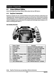
...Display Description 1. for special enhancement for CPU and Memory, 3) Smart-Fan control for managing fan speed control of CPU frequency 8. GO Confirmation and Execution button 6. Appendix Featuring several powerful yet easy to GIGABYTE website 10. Function display LEDs Shows... the current functions status 9. Display screen Display panel of both CPU cooling fan and North-Bridge Chipset cooling fan, 4) PC health for enhancing system performance, 2) C.I .B. GIGABYTE Logo Log on different motherboards. - 55 - and M.I .B. English Chapter...
...Display Description 1. for special enhancement for CPU and Memory, 3) Smart-Fan control for managing fan speed control of CPU frequency 8. GO Confirmation and Execution button 6. Appendix Featuring several powerful yet easy to GIGABYTE website 10. Function display LEDs Shows... the current functions status 9. Display screen Display panel of both CPU cooling fan and North-Bridge Chipset cooling fan, 4) PC health for enhancing system performance, 2) C.I .B. GIGABYTE Logo Log on different motherboards. - 55 - and M.I .B. English Chapter...


