Manual
Page 7
Chapter 3 Drivers Installation 57 3-1 Install Chipset Drivers 57 3-2 SoftwareApplication 58 3-3 Software Information 58 3-4 Hardware Information 59 3-5 Contact Us ...59 Chapter 4 Appendix 61 4-1 Unique Software Utilities 61 4-1-1 EasyTune 5 Introduction 62 4-1-2 Xpress Recovery2 Introduction 63 4-1-3 Flash BIOS Method Introduction 65 4-1-4 Serial ATA BIOS Setting Utility Introduction 76 4-1-5 2- / 4- / 6- / 8- Channel Audio Function Introduction 87 4-2 Troubleshooting 91 - 7 -
Chapter 3 Drivers Installation 57 3-1 Install Chipset Drivers 57 3-2 SoftwareApplication 58 3-3 Software Information 58 3-4 Hardware Information 59 3-5 Contact Us ...59 Chapter 4 Appendix 61 4-1 Unique Software Utilities 61 4-1-1 EasyTune 5 Introduction 62 4-1-2 Xpress Recovery2 Introduction 63 4-1-3 Flash BIOS Method Introduction 65 4-1-4 Serial ATA BIOS Setting Utility Introduction 76 4-1-5 2- / 4- / 6- / 8- Channel Audio Function Introduction 87 4-2 Troubleshooting 91 - 7 -

Manual
Page 18
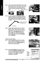
.... Remove your system requirements. - 18 - Replace your VGA card is locked by following the steps outlined below: 1. P4 nForce4 SLI Series Motherboard The PCIE_12V power connector supplies extra power to secure the slot bracket of expansion card from BIOS. 8. English 1-6 Installation...the expansion card. 6. Replace the screw to the PCI Express x 16 slots. Make sure your computer's chassis cover. 7. Install related driver from the computer. 3. Read the related expansion card's instruction document before install the expansion card into expansion slot in the slot. 5. ...
.... Remove your system requirements. - 18 - Replace your VGA card is locked by following the steps outlined below: 1. P4 nForce4 SLI Series Motherboard The PCIE_12V power connector supplies extra power to secure the slot bracket of expansion card from BIOS. 8. English 1-6 Installation...the expansion card. 6. Replace the screw to the PCI Express x 16 slots. Make sure your computer's chassis cover. 7. Install related driver from the computer. 3. Read the related expansion card's instruction document before install the expansion card into expansion slot in the slot. 5. ...
Manual
Page 22
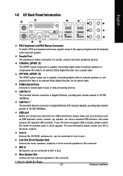
... to the SLI gold edge connector on top of both cards. Female slots on the bridge connector Gold edge connector on the top of graphics card Step 3: In order to the chassis back panel with a screw. Graphics Card Driver Setting: Step 1: After installing graphics card driver in operating system..., right-click the NVIDIA icon in the SLI multi-GPU dialog box. The NVIDIA control panel will restart after you must install the ...
... to the SLI gold edge connector on top of both cards. Female slots on the bridge connector Gold edge connector on the top of graphics card Step 3: In order to the chassis back panel with a screw. Graphics Card Driver Setting: Step 1: After installing graphics card driver in operating system..., right-click the NVIDIA icon in the SLI multi-GPU dialog box. The NVIDIA control panel will restart after you must install the ...
Manual
Page 23
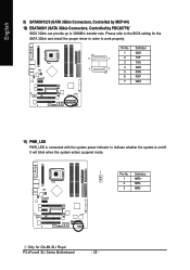
...to this connector. have a standard USB interface. Also make sure your OS does not support USB controller, please contact OS vendor for GA-8N-SLI Royal. - 23 - For more information please contact your device(s) into USB connector(s), please make sureyour OS supports USB controller. Rear Speaker... Port) Connects to the lower port (purple). USB port Before you connect your OS or device(s) vendors. Only for possible patch or driver upgrade. Line In Devices like CD-ROM, walkman etc. can be connected to this connector. Line Out (Front Speaker Out) Connect the...
...to this connector. have a standard USB interface. Also make sure your OS does not support USB controller, please contact OS vendor for GA-8N-SLI Royal. - 23 - For more information please contact your device(s) into USB connector(s), please make sureyour OS supports USB controller. Rear Speaker... Port) Connects to the lower port (purple). USB port Before you connect your OS or device(s) vendors. Only for possible patch or driver upgrade. Line In Devices like CD-ROM, walkman etc. can be connected to this connector. Line Out (Front Speaker Out) Connect the...
Manual
Page 28
... power indicator to 300MB/s transfer rate. Pin No. Definition 1 MPD+ 2 MPD- 3 MPD- Only for the SATA 3Gb/s and install the proper driver in order to the BIOS setting for GA-8N-SLI Royal. P4 nForce4 SLI Series Motherboard - 28 - It will blink when the system enters suspend mode. 1 Pin No. Please refer to work properly.
... power indicator to 300MB/s transfer rate. Pin No. Definition 1 MPD+ 2 MPD- 3 MPD- Only for the SATA 3Gb/s and install the proper driver in order to the BIOS setting for GA-8N-SLI Royal. P4 nForce4 SLI Series Motherboard - 28 - It will blink when the system enters suspend mode. 1 Pin No. Please refer to work properly.

Manual
Page 57
... XP operating system, please use Windows Service Pack. System will reboot automatically after install the drivers, afterward you want then click the "GO" button. Drivers Installation The "Xpress Install" will execute the installation for GA-8N-SLI Royal. - 57 - English Chapter 3 Drivers Installation Pictures below are shown in "My computer", and execute the Setup.exe. 3-1 Install...
... XP operating system, please use Windows Service Pack. System will reboot automatically after install the drivers, afterward you want then click the "GO" button. Drivers Installation The "Xpress Install" will execute the installation for GA-8N-SLI Royal. - 57 - English Chapter 3 Drivers Installation Pictures below are shown in "My computer", and execute the Setup.exe. 3-1 Install...

Manual
Page 58
P4 nForce4 SLI Series Motherboard - 58 - English 3-2 Software Application This page displays all the tools that Gigabyte developed and some free software, you can choose anyone you want and press "install" to install them. 3-3 Software Information This page lists the contents of software and drivers in this CD-title.
P4 nForce4 SLI Series Motherboard - 58 - English 3-2 Software Application This page displays all the tools that Gigabyte developed and some free software, you can choose anyone you want and press "install" to install them. 3-3 Software Information This page lists the contents of software and drivers in this CD-title.
Manual
Page 59
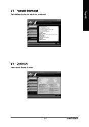
Drivers Installation English 3-4 Hardware Information This page lists all device you have for this motherboard. 3-5 Contact Us Please see the last page for details. - 59 -
Drivers Installation English 3-4 Hardware Information This page lists all device you have for this motherboard. 3-5 Contact Us Please see the last page for details. - 59 -
Manual
Page 61
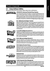
...system management tool that eliminates system boot-up -to be monitored and controlled via the Internet, C.O.M. Designed to 10%. With GIGABYTE's proprietary S.O.S. automatically resets the overclocked system settings back to their factory defaults to provide a more user-friendly and reliable platform...'s are able to optimize memory performance by selecting from system over-enhancement by the user. to -date drivers and BIOS.(Do not use C.O.M. Through GIGABYTE M.I .A. 2) is designed to automatically adjust CPU computing power to control and enhance their system. feature the...
...system management tool that eliminates system boot-up -to be monitored and controlled via the Internet, C.O.M. Designed to 10%. With GIGABYTE's proprietary S.O.S. automatically resets the overclocked system settings back to their factory defaults to provide a more user-friendly and reliable platform...'s are able to optimize memory performance by selecting from system over-enhancement by the user. to -date drivers and BIOS.(Do not use C.O.M. Through GIGABYTE M.I .A. 2) is designed to automatically adjust CPU computing power to control and enhance their system. feature the...
Manual
Page 63
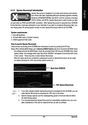
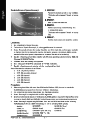
...to enter Xpress Recovery2. GA-8N-SLI Royal F5a . . . . :BIOS Setup/Q-Flash, : Xpress Recovery2, For Boot Menu 11/16/2005-C19-MCP04-6A61EG0FC-00 Xpress Recovery2 1. System storage capacity and the reading/writing speed of hard disk data. At least 64M bytes of OS and all required drivers as well as software...Xpress Recovery2 later, you can simply press F9 during system power-on PATA and SATA IDE controllers. Intel x86 platforms 2. Insert the provided driver CD into your hard disk. Boot from CD/DVD:" will stay permanent in your CD-ROM drive. Press any key to enter Xpress...
...to enter Xpress Recovery2. GA-8N-SLI Royal F5a . . . . :BIOS Setup/Q-Flash, : Xpress Recovery2, For Boot Menu 11/16/2005-C19-MCP04-6A61EG0FC-00 Xpress Recovery2 1. System storage capacity and the reading/writing speed of hard disk data. At least 64M bytes of OS and all required drivers as well as software...Xpress Recovery2 later, you can simply press F9 during system power-on PATA and SATA IDE controllers. Intel x86 platforms 2. Insert the provided driver CD into your hard disk. Boot from CD/DVD:" will stay permanent in your CD-ROM drive. Press any key to enter Xpress...
Manual
Page 64
...disks with Windows operating systems including DOS and Windows XP/2000/NT/9x/Me. 5. BACKUP: Back up data from the driver CD before data backup. 2. REMOVE: Remove previously-created backup files to release disk space. (This button will not appear...Xpress Recovery2, a primary partition must be solved by BIOS update) GA-K8U GA-K8NXP-9 GA-8N-SLI Royal GA-K8U-9 GA-K8N Ultra-9 GA-8N-SLI Pro GA-K8NXP-SLI GA-K8NF-9 (PCB Ver. 1.0) GA-8N-SLI GA-K8N Ultra-SLI GA-K8NE (PCB Ver. 1.0) GA-K8N Pro-SLI GA-K8NMF-9 P4 nForce4 SLI Series Motherboard - 64 - USB hard disks are currently not ...
...disks with Windows operating systems including DOS and Windows XP/2000/NT/9x/Me. 5. BACKUP: Back up data from the driver CD before data backup. 2. REMOVE: Remove previously-created backup files to release disk space. (This button will not appear...Xpress Recovery2, a primary partition must be solved by BIOS update) GA-K8U GA-K8NXP-9 GA-8N-SLI Royal GA-K8U-9 GA-K8N Ultra-9 GA-8N-SLI Pro GA-K8NXP-SLI GA-K8NF-9 (PCB Ver. 1.0) GA-8N-SLI GA-K8N Ultra-SLI GA-K8NE (PCB Ver. 1.0) GA-K8N Pro-SLI GA-K8NMF-9 P4 nForce4 SLI Series Motherboard - 64 - USB hard disks are currently not ...

Manual
Page 77
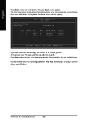
.... (For more detailed setup information, please visit "Support\ Motherboard\ Technology Guide section" on our website at http:\\www.gigabyte.com.tw to read or download the information you need.) Configuring the Nvidia RAID BIOS The NVRAID BIOS setup lets you ... RAID Mode: Mirroring MediaShield RAID Utility Feb 8 2005 - More information on the motherboard ie. Press F10 to select Silicon Image). 5) Complete driver installation. 6) Complete RAID utility installation. Striping Block: Optimal Free Disks Loc Disk Model Name 2.0.M ST3120026AS 2.1.M ST3120026AS Array Disks Loc Disk Model Name...
.... (For more detailed setup information, please visit "Support\ Motherboard\ Technology Guide section" on our website at http:\\www.gigabyte.com.tw to read or download the information you need.) Configuring the Nvidia RAID BIOS The NVRAID BIOS setup lets you ... RAID Mode: Mirroring MediaShield RAID Utility Feb 8 2005 - More information on the motherboard ie. Press F10 to select Silicon Image). 5) Complete driver installation. 6) Complete RAID utility installation. Striping Block: Optimal Free Disks Loc Disk Model Name 2.0.M ST3120026AS 2.1.M ST3120026AS Array Disks Loc Disk Model Name...
Manual
Page 80
... shows various information about the array that the RAID setup has been configured from the RAID BIOS, the next step is to configure and load drivers under Windows. Now that you want to wipe out all its contents, press C. At the prompt, press Y to mark this disk as Striping ...Block used, RAID Mode, Striping Width, Disk Model Name, and disk capacity. P4 nForce4 SLI Series Motherboard - 80 - The Array Detail screen appears. RAID Mode: Mirroring Striping Width : 1 Array 2 : NVIDIA MIRROR 111.79G - Press Enter again to go ...
... shows various information about the array that the RAID setup has been configured from the RAID BIOS, the next step is to configure and load drivers under Windows. Now that you want to wipe out all its contents, press C. At the prompt, press Y to mark this disk as Striping ...Block used, RAID Mode, Striping Width, Disk Model Name, and disk capacity. P4 nForce4 SLI Series Motherboard - 80 - The Array Detail screen appears. RAID Mode: Mirroring Striping Width : 1 Array 2 : NVIDIA MIRROR 111.79G - Press Enter again to go ...

Manual
Page 86
...Step 3: After completing the steps, boot from the menu. P4 nForce4 SLI Series Motherboard - 86 - Press F6 as soon as you see the "Press F6 if you need to a floppy disk. After that, the driver will have to that in MS-DOS mode(Note1). From the CD-...driver file to be recognized during OS installation. Press 0 to copy the driver in Fig. 2. Follow the on-screen instructions to complete the installation. (Each time you add a new hard drive to a RAID array, the RAID driver will not have to the floppy disk. Use an alternative system and insert the GIGABYTE motherboard driver...
...Step 3: After completing the steps, boot from the menu. P4 nForce4 SLI Series Motherboard - 86 - Press F6 as soon as you see the "Press F6 if you need to a floppy disk. After that, the driver will have to that in MS-DOS mode(Note1). From the CD-...driver file to be recognized during OS installation. Press 0 to copy the driver in Fig. 2. Follow the on-screen instructions to complete the installation. (Each time you add a new hard drive to a RAID array, the RAID driver will not have to the floppy disk. Use an alternative system and insert the GIGABYTE motherboard driver...
Manual
Page 87
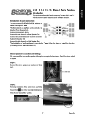
...-ROM/DVD-ROM, walkman or others audio input to Line Out (Front Speaker Out). Connect microphone to Side Speaker Out. The installation of the audio driver, you use the speaker with amplifier to use 2-/ 4-/6-/8-channnels audio feature by audio software selection. Please follow the steps to install the function. (Following pictures...
...-ROM/DVD-ROM, walkman or others audio input to Line Out (Front Speaker Out). Connect microphone to Side Speaker Out. The installation of the audio driver, you use the speaker with amplifier to use 2-/ 4-/6-/8-channnels audio feature by audio software selection. Please follow the steps to install the function. (Following pictures...
Manual
Page 88
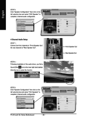
... 3: Click "Speaker Configuration" then click on the left selection bar and select "4CH Speaker" to complete 4 channel audio configuration. STEP 2 : Following installation of the audio driver, you find a Sound Effect icon on the left selection bar and select "2CH Speaker" to complete 2 channel audio configuration. 4 Channel Audio Setup STEP 1 : Connect the... "Speaker Configuration" then click on the lower right hand taskbar. Front Speaker Out Rear Speaker Out Click the icon to "Rear Speaker Out". P4 nForce4 SLI Series Motherboard - 88 -
... 3: Click "Speaker Configuration" then click on the left selection bar and select "4CH Speaker" to complete 4 channel audio configuration. STEP 2 : Following installation of the audio driver, you find a Sound Effect icon on the left selection bar and select "2CH Speaker" to complete 2 channel audio configuration. 4 Channel Audio Setup STEP 1 : Connect the... "Speaker Configuration" then click on the lower right hand taskbar. Front Speaker Out Rear Speaker Out Click the icon to "Rear Speaker Out". P4 nForce4 SLI Series Motherboard - 88 -
Manual
Page 89
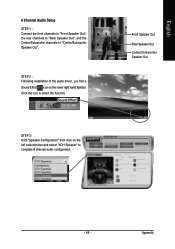
English 6 Channel Audio Setup STEP 1 : Connect the front channels to "Front Speaker Out", the rear channels to "Rear Speaker Out", and the Center/Subwoofer channels to complete 6 channel audio configuration. Front Speaker Out Rear Speaker Out Center/Subwoofer Speaker Out - 89 - Appendix STEP 3: Click "Speaker Configuration" then click on the lower right hand taskbar. STEP 2 : Following installation of the audio driver, you find a Sound Effect icon on the left selection bar and select "6CH Speaker" to "Center/Subwoofer Speaker Out". Click the icon to select the function.
English 6 Channel Audio Setup STEP 1 : Connect the front channels to "Front Speaker Out", the rear channels to "Rear Speaker Out", and the Center/Subwoofer channels to complete 6 channel audio configuration. Front Speaker Out Rear Speaker Out Center/Subwoofer Speaker Out - 89 - Appendix STEP 3: Click "Speaker Configuration" then click on the lower right hand taskbar. STEP 2 : Following installation of the audio driver, you find a Sound Effect icon on the left selection bar and select "6CH Speaker" to "Center/Subwoofer Speaker Out". Click the icon to select the function.
Manual
Page 90
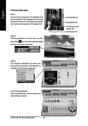
P4 nForce4 SLI Series Motherboard - 90 - STEP 3: Click "Speaker Configuration" then click on the lower right hand taskbar. English 8 Channel Audio Setup STEP 1 : Connect the front channels to "... Side Speaker Out Sound Effect Configuration: At the sound effect menu, users can adjust sound option settings as desired. STEP 2 : Following installation of the audio driver, you find a Sound Effect icon on the left selection bar and select "8CH Speaker" to "Side Speaker Out". Click the icon to select the function...
P4 nForce4 SLI Series Motherboard - 90 - STEP 3: Click "Speaker Configuration" then click on the lower right hand taskbar. English 8 Channel Audio Setup STEP 1 : Connect the front channels to "... Side Speaker Out Sound Effect Configuration: At the sound effect menu, users can adjust sound option settings as desired. STEP 2 : Following installation of the audio driver, you find a Sound Effect icon on the left selection bar and select "8CH Speaker" to "Side Speaker Out". Click the icon to select the function...
Manual
Page 1
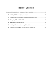
Table of Contents Configuring SATA Hard Drive(s) (Controller: nVIDIA nForce4 SLI 2 (1) Installing SATA hard drive(s) in your computer 2 (2) Configuring SATA controller mode and boot sequence in BIOS Setup 2 (3) Configuring RAID set in RAID BIOS 6 (4) Making a SATA controller driver disk 9 (5) Installing SATA controller driver during OS installation 11 (6) Configuring a bootable RAID array with Microsoft Windows 2000 14
Table of Contents Configuring SATA Hard Drive(s) (Controller: nVIDIA nForce4 SLI 2 (1) Installing SATA hard drive(s) in your computer 2 (2) Configuring SATA controller mode and boot sequence in BIOS Setup 2 (3) Configuring RAID set in RAID BIOS 6 (4) Making a SATA controller driver disk 9 (5) Installing SATA controller driver during OS installation 11 (6) Configuring a bootable RAID array with Microsoft Windows 2000 14

Manual
Page 2
... the SATA controller. In the example in RAID BIOS. (4) Make a floppy disk containing the SATA controller driver. (5) Install the SATA controller driver during POST (Power-On Self Test). SATA Configurations (P4 nForce4 SLI series) - 2 - "*" Skip this step if you do not want to ensure optimal performance, it...to make sure that you may prepare only one hard drive. (b) An empty formatted floppy disk. (c) Windows XP/2000 setup disk. (d) Driver CD for your motherboard. (1) Installing SATA hard drive(s) in BIOS Setup You have to identify the SATA controller for the SATA hard drive(s)/...
... the SATA controller. In the example in RAID BIOS. (4) Make a floppy disk containing the SATA controller driver. (5) Install the SATA controller driver during POST (Power-On Self Test). SATA Configurations (P4 nForce4 SLI series) - 2 - "*" Skip this step if you do not want to ensure optimal performance, it...to make sure that you may prepare only one hard drive. (b) An empty formatted floppy disk. (c) Windows XP/2000 setup disk. (d) Driver CD for your motherboard. (1) Installing SATA hard drive(s) in BIOS Setup You have to identify the SATA controller for the SATA hard drive(s)/...


