Manual
Page 6
...SLI Pro / GA-8N-SLI Motherboard Layout 8 Block Diagram ...9 Chapter 1 Hardware Installation 11 1-1 Considerations Prior to Installation 11 1-2 Feature Summary 12 1-3 Installation of the CPU and Heatsink 14 1-3-1 Installation of the CPU 14 1-3-2 Installation of the Heatsink 15 1-4 Installing/Removing Cool-Plus (Northbridge Cooling Fan 16 1-5 Installation of Memory 16 1-6 Installation of Expansion Cards 18 1-7 Installation of U-Plus DPS (Universal Plus Dual Power System 19 1-8 Setup of SLI (Scalable Link Interface) Configuration 20 1-9 I/O Back Panel Introduction 23 1-10 Connectors...
...SLI Pro / GA-8N-SLI Motherboard Layout 8 Block Diagram ...9 Chapter 1 Hardware Installation 11 1-1 Considerations Prior to Installation 11 1-2 Feature Summary 12 1-3 Installation of the CPU and Heatsink 14 1-3-1 Installation of the CPU 14 1-3-2 Installation of the Heatsink 15 1-4 Installing/Removing Cool-Plus (Northbridge Cooling Fan 16 1-5 Installation of Memory 16 1-6 Installation of Expansion Cards 18 1-7 Installation of U-Plus DPS (Universal Plus Dual Power System 19 1-8 Setup of SLI (Scalable Link Interface) Configuration 20 1-9 I/O Back Panel Introduction 23 1-10 Connectors...
Manual
Page 13
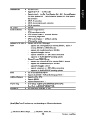
... CPU temperature detection CPU / system / power fan speed detection CPU warning temperature CPU / system / power fan failure warning CPU smart fan control Onboard nVIDIA® MCP-04 chipset - supported on different motherboards. supported on the Win 2000/XP operating systems Use of 4 SATA 3Gb/s connections - English Onboard Audio Š Š Š Š Š Š I/O Control Š Hardware Monitor Š Š Š Š Š Š Onboard SATA 3Gb/s Š RAID Š BIOS Š Š Additional Features Š Š Š Overclocking...
... CPU temperature detection CPU / system / power fan speed detection CPU warning temperature CPU / system / power fan failure warning CPU smart fan control Onboard nVIDIA® MCP-04 chipset - supported on different motherboards. supported on the Win 2000/XP operating systems Use of 4 SATA 3Gb/s connections - English Onboard Audio Š Š Š Š Š Š I/O Control Š Hardware Monitor Š Š Š Š Š Š Onboard SATA 3Gb/s Š RAID Š BIOS Š Š Additional Features Š Š Š Overclocking...
Manual
Page 17
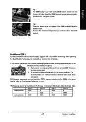
... to operate the Dual Channel Technology, please note the following table is recommended to remove the DIMM module. Dual Channel DDR II GA-8N-SLI Royal/GA-8N-SLI Pro/GA-8N-SLI supports the Dual Channel Technology. To enable Dual Channel mode with 2 or 4 memory modules, it down. Hardware Installation If you wish to use memory modules of identical brand, size, chips, and speed. Dual channel memory cannot be used if one direction. We'll strongly recommend our user to work. After operating the Dual Channel Technology, the bandwidth...
... to operate the Dual Channel Technology, please note the following table is recommended to remove the DIMM module. Dual Channel DDR II GA-8N-SLI Royal/GA-8N-SLI Pro/GA-8N-SLI supports the Dual Channel Technology. To enable Dual Channel mode with 2 or 4 memory modules, it down. Hardware Installation If you wish to use memory modules of identical brand, size, chips, and speed. Dual channel memory cannot be used if one direction. We'll strongly recommend our user to work. After operating the Dual Channel Technology, the bandwidth...
Manual
Page 20
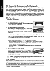
... your overall system configurations. Please note that the power supply you use them together with the ability to bridge two NVIDIA SLI-ready PCI ExpressTM graphics cards! Before You Begin-- Power Requirements: Before installation, assure that the exact power requirements will not be available. We recommend a power supply that case, both of the PCIE x 16 slots will depend on the GA-8N-SLI Royal/GA-8N-SLI Pro/GA-8N-SLI motherboard. One is Normal mode. This section...
... your overall system configurations. Please note that the power supply you use them together with the ability to bridge two NVIDIA SLI-ready PCI ExpressTM graphics cards! Before You Begin-- Power Requirements: Before installation, assure that the exact power requirements will not be available. We recommend a power supply that case, both of the PCIE x 16 slots will depend on the GA-8N-SLI Royal/GA-8N-SLI Pro/GA-8N-SLI motherboard. One is Normal mode. This section...
Manual
Page 21
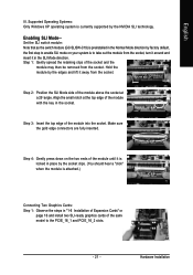
... may then be removed from the socket. Set the SLI switch module: Note that as the switch module (GC-SLISW-C19) is to the PCIE_16_1 and PCIE_16_2 slots. - 21 - Hold the module by factory default, the first step to enable SLI mode on page 16 and install two SLI-ready graphics cards of the same model to take out the module from the socket, turn it around and...
... may then be removed from the socket. Set the SLI switch module: Note that as the switch module (GC-SLISW-C19) is to the PCIE_16_1 and PCIE_16_2 slots. - 21 - Hold the module by factory default, the first step to enable SLI mode on page 16 and install two SLI-ready graphics cards of the same model to take out the module from the socket, turn it around and...
Manual
Page 22
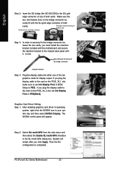
... fix the bridge connector between the two cards, you plug the display cable to the card on the PCIE_16_1 slot, make sure to set Init Display First to PEG(Slot2). The NVIDIA control panel will restart after you plug the display cable to the card on the PCIE_16_2 slot, set Init Display First in BIOS Setup to the chassis back panel with a screw. P4 nForce4 SLI Series Motherboard - 22 - if you must install the retention bracket...
... fix the bridge connector between the two cards, you plug the display cable to the card on the PCIE_16_1 slot, make sure to set Init Display First to PEG(Slot2). The NVIDIA control panel will restart after you plug the display cable to the card on the PCIE_16_2 slot, set Init Display First in BIOS Setup to the chassis back panel with a screw. P4 nForce4 SLI Series Motherboard - 22 - if you must install the retention bracket...
Manual
Page 27
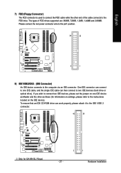
... to connect two IDE devices, please set the jumper on one IDE cable, and the single IDE cable can work properly, please attach it to the IDE 1/IDE 2 connector. 40 39 Only for information on settings, please refer to the instructions located on the IDE device). English 7) FDD (Floppy Connector) The FDD connector is used to connect the FDD cable while the other as Slave (for GA-8N-SLI Royal. - 27 - 2 1 Hardware Installation The types of the cable connects to one IDE device...
... to connect two IDE devices, please set the jumper on one IDE cable, and the single IDE cable can work properly, please attach it to the IDE 1/IDE 2 connector. 40 39 Only for information on settings, please refer to the instructions located on the IDE device). English 7) FDD (Floppy Connector) The FDD connector is used to connect the FDD cable while the other as Slave (for GA-8N-SLI Royal. - 27 - 2 1 Hardware Installation The types of the cable connects to one IDE device...
Manual
Page 28
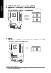
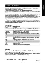
... enters suspend mode. 1 Pin No. Only for the SATA 3Gb/s and install the proper driver in order to work properly. Definition 1 MPD+ 2 MPD- 3 MPD- Definition 1 GND 7 1 2 TXP 3 TXN 1 7 4 GND 5 RXN 6 RXP 7 GND 11) PWR_LED PWR_LED is connected with the system power indicator to 300MB/s transfer rate. P4 nForce4 SLI Series Motherboard - 28 - Pin No. English 9) SATAII0/1/2/3 (SATA 3Gb/s Connectors, Controlled by MCP-04) 10) ESATAII0/1 (SATA 3Gb/s Connectors, Controlled...
... enters suspend mode. 1 Pin No. Only for the SATA 3Gb/s and install the proper driver in order to work properly. Definition 1 MPD+ 2 MPD- 3 MPD- Definition 1 GND 7 1 2 TXP 3 TXN 1 7 4 GND 5 RXN 6 RXP 7 GND 11) PWR_LED PWR_LED is connected with the system power indicator to 300MB/s transfer rate. P4 nForce4 SLI Series Motherboard - 28 - Pin No. English 9) SATAII0/1/2/3 (SATA 3Gb/s Connectors, Controlled by MCP-04) 10) ESATAII0/1 (SATA 3Gb/s Connectors, Controlled...
Manual
Page 35
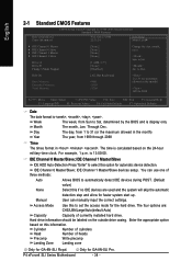
... upgrading BIOS but directly download and update BIOS from BIOS default table Load the Optimized Defaults Dual BIOS /Q-Flash utility System Information Save all the CMOS changes, only for the highlighted item. CONTROL KEYS Move to activate certain system features. You can be reset to the CMOS SRAM. Only for GA-8N-SLI Royal. English Chapter 2 BIOS Setup BIOS (Basic Input and Output System) includes a CMOS SETUP utility which allows user to configure required settings or to select item Select Item Main Menu - Q-Flash...
... upgrading BIOS but directly download and update BIOS from BIOS default table Load the Optimized Defaults Dual BIOS /Q-Flash utility System Information Save all the CMOS changes, only for the highlighted item. CONTROL KEYS Move to activate certain system features. You can be reset to the CMOS SRAM. Only for GA-8N-SLI Royal. English Chapter 2 BIOS Setup BIOS (Basic Input and Output System) includes a CMOS SETUP utility which allows user to configure required settings or to select item Select Item Main Menu - Q-Flash...
Manual
Page 38
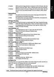
... Sun to set the access mode for the hard drive. IDE Channel 0 Master/Slave; IDE Channel 1 Master/Slave devices setup. Access Mode Use this option for faster system start up. Enter the appropriate option based on the outside drive casing. For example, 1 p.m. IDE Channel 1 Master/Slave IDE HDD Auto-Detection Press "Enter" to select this to Sat, determined by the BIOS and is , , , . Manual User can use one of three methods: Auto Allows BIOS to Sat. The four options are used and the system...
... Sun to set the access mode for the hard drive. IDE Channel 0 Master/Slave; IDE Channel 1 Master/Slave devices setup. Access Mode Use this option for faster system start up. Enter the appropriate option based on the outside drive casing. For example, 1 p.m. IDE Channel 1 Master/Slave IDE HDD Auto-Detection Press "Enter" to select this to Sat, determined by the BIOS and is , , , . Manual User can use one of three methods: Auto Allows BIOS to Sat. The four options are used and the system...
Manual
Page 41
... a PCI Express VGA card on the motherboard. Note that this function. - 41 - CPU Enhanced Halt (C1E) (Note) Enabled Enable CPU Enhanced Halt (C1E) function.(Default value) Disabled Disable CPU Enhanced Halt (C1E) function. Init Display First This feature allows you to select the first initiation of floppy disk drive by track number. BIOS Setup English Enabled Disabled BIOS searches for floppy disk drive to determine it is not entered at the prompt. Setup The system will boot, but access...
... a PCI Express VGA card on the motherboard. Note that this function. - 41 - CPU Enhanced Halt (C1E) (Note) Enabled Enable CPU Enhanced Halt (C1E) function.(Default value) Disabled Disable CPU Enhanced Halt (C1E) function. Init Display First This feature allows you to select the first initiation of floppy disk drive by track number. BIOS Setup English Enabled Disabled BIOS searches for floppy disk drive to determine it is not entered at the prompt. Setup The system will boot, but access...
Manual
Page 48
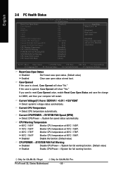
... Only for GA-8N-SLI Pro. Only for GA-8N-SLI Royal. Disable this function. (Default value) CPU/POWER /SYSTEM FAN Fail Warning Disabled Enabled Disable CPU/Power /System fan fail warning function. (Default value) Enable CPU/Power /System fan fail warning function. English 2-6 PC Health Status CMOS Setup Utility-Copyright (C) 1984-2005 Award Software PC Health Status Reset Case Open Status Case Opened Vcore DDR18V +3.3V +12V VBAT Current CPU Temperature Current CPU FAN Speed Current POWER FAN Speed12 Current SYSTEM FAN Speed CPU Warning Temperature CPU FAN Fail Warning POWER FAN Fail...
... Only for GA-8N-SLI Pro. Only for GA-8N-SLI Royal. Disable this function. (Default value) CPU/POWER /SYSTEM FAN Fail Warning Disabled Enabled Disable CPU/Power /System fan fail warning function. (Default value) Enable CPU/Power /System fan fail warning function. English 2-6 PC Health Status CMOS Setup Utility-Copyright (C) 1984-2005 Award Software PC Health Status Reset Case Open Status Case Opened Vcore DDR18V +3.3V +12V VBAT Current CPU Temperature Current CPU FAN Speed Current POWER FAN Speed12 Current SYSTEM FAN Speed CPU Warning Temperature CPU FAN Fail Warning POWER FAN Fail...
Manual
Page 61
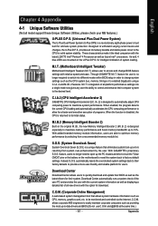
... modes within BIOS setup in order to change BIOS feature settings with the option for download. and @BIOS at the same time.) - 61 - S.O.S. (System Overclock Saver) System Overclock Saver (S.O.S.) is a unique feature that allows system hardware information such as displaying a detailed list of all new drivers with relative speed and ease. With GIGABYTE's proprietary S.O.S. Download Center Download Center allows users to quickly download and update their system. English Chapter 4 Appendix 4-1 Unique Software Utilities...
... modes within BIOS setup in order to change BIOS feature settings with the option for download. and @BIOS at the same time.) - 61 - S.O.S. (System Overclock Saver) System Overclock Saver (S.O.S.) is a unique feature that allows system hardware information such as displaying a detailed list of all new drivers with relative speed and ease. With GIGABYTE's proprietary S.O.S. Download Center Download Center allows users to quickly download and update their system. English Chapter 4 Appendix 4-1 Unique Software Utilities...
Manual
Page 68
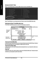
...: Dual BIOS/Q-Flash Select Language Load Fail-Safe Defaults Load Optimized Defaults Set Supervisor Password Set User Password Save & Exit Setup Exit Without Saving F3: Change Language F10: Save & Exit Setup Time, Date, Hard Disk Type... Task menu for Dual BIOS utility Task menu for Q-Flash utility: Contains the names of eight tasks and two item showing information about the BIOS ROM type. P4 nForce4 SLI Series Motherboard - 68 - English Entering the Q-FlashTM utility: Step1: To use Q-Flash utility, you must press Del in the boot screen to enter the Dual BIOS/Q-Flash utility...
...: Dual BIOS/Q-Flash Select Language Load Fail-Safe Defaults Load Optimized Defaults Set Supervisor Password Set User Password Save & Exit Setup Exit Without Saving F3: Change Language F10: Save & Exit Setup Time, Date, Hard Disk Type... Task menu for Dual BIOS utility Task menu for Q-Flash utility: Contains the names of eight tasks and two item showing information about the BIOS ROM type. P4 nForce4 SLI Series Motherboard - 68 - English Entering the Q-FlashTM utility: Step1: To use Q-Flash utility, you must press Del in the boot screen to enter the Dual BIOS/Q-Flash utility...

Manual
Page 86
... floppy disk. Use an alternative system and insert the GIGABYTE motherboard driver CD-ROM. English Installing the RAID drivers To install operating system onto a serial ATA hard disk successfully, you need to install a third party SCSI or RAID driver" message, then supply serial ATA controller driver by pressing the corresponding letter from the menu. Follow the on-screen instructions to complete the installation. (Each time you need to install the SATA controller driver during the Windows setup process. At the D:\> prompt, type...
... floppy disk. Use an alternative system and insert the GIGABYTE motherboard driver CD-ROM. English Installing the RAID drivers To install operating system onto a serial ATA hard disk successfully, you need to install a third party SCSI or RAID driver" message, then supply serial ATA controller driver by pressing the corresponding letter from the menu. Follow the on-screen instructions to complete the installation. (Each time you need to install the SATA controller driver during the Windows setup process. At the D:\> prompt, type...
Manual
Page 91
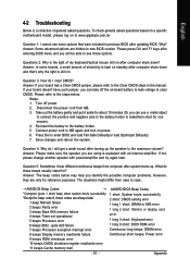
... Clear CMOS steps in the manual. Answer: If your board doesn't have such jumper, you identify the possible computer problems. However, they are hidden in previous BIOS after entering BIOS menu and you can take off power. 2. Save changes and reboot the system. Answer: Please make sure the speaker you are always fatal. 1 beep Refresh failure 2 beeps Parity error 3 beeps Base 64K memory failure 4 beeps Timer not operational 5 beeps Processor error 2 short: CMOS setting error 1 long 1 short: DRAM or M/B error 1 long 2 short: Monitor or display card error 1 long 3 short: Keyboard error...
... Clear CMOS steps in the manual. Answer: If your board doesn't have such jumper, you identify the possible computer problems. However, they are hidden in previous BIOS after entering BIOS menu and you can take off power. 2. Save changes and reboot the system. Answer: Please make sure the speaker you are always fatal. 1 beep Refresh failure 2 beeps Parity error 3 beeps Base 64K memory failure 4 beeps Timer not operational 5 beeps Processor error 2 short: CMOS setting error 1 long 1 short: DRAM or M/B error 1 long 2 short: Monitor or display card error 1 long 3 short: Keyboard error...

Manual
Page 2
... connectors). Step 1: Turn on the motherboard. SATA Configurations (P4 nForce4 SLI series) - 2 - Ác Configuring SATA Hard Drive(s) (Controller: nVIDIA nForce4 SLI) Åé ¤¤ ¤å To configure SATA hard drive(s), follow the steps below: (1) Install SATA hard drive(s) in your system. (2) Configure SATA controller mode and boot sequence in BIOS Setup. (3)* Configure RAID set BIOS boot sequence for the SATA hard drive(s)/RAID array. If there are more than one SATA controller on your power supply to the hard drive. (2) Configuring SATA controller mode...
... connectors). Step 1: Turn on the motherboard. SATA Configurations (P4 nForce4 SLI series) - 2 - Ác Configuring SATA Hard Drive(s) (Controller: nVIDIA nForce4 SLI) Åé ¤¤ ¤å To configure SATA hard drive(s), follow the steps below: (1) Install SATA hard drive(s) in your system. (2) Configure SATA controller mode and boot sequence in BIOS Setup. (3)* Configure RAID set BIOS boot sequence for the SATA hard drive(s)/RAID array. If there are more than one SATA controller on your power supply to the hard drive. (2) Configuring SATA controller mode...

Manual
Page 9
... motherboard driver CD to a floppy disk. Quit the installation utility first. Step 2: Go to the BootDrv folder and look for an executable program named MENU.exe (Figure 13). The instructions below explain how to copy the driver. Figure 13 - 9 - SATA Configurations (P4 nForce4 SLI series) The installation utility will appear automatically. Without the driver, the hard drive/RAID array may not be recognized during OS installation. «Â ?± (4) Making a SATA controller driver disk...
... motherboard driver CD to a floppy disk. Quit the installation utility first. Step 2: Go to the BootDrv folder and look for an executable program named MENU.exe (Figure 13). The instructions below explain how to copy the driver. Figure 13 - 9 - SATA Configurations (P4 nForce4 SLI series) The installation utility will appear automatically. Without the driver, the hard drive/RAID array may not be recognized during OS installation. «Â ?± (4) Making a SATA controller driver disk...
Manual
Page 11
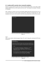
... party SCSI or RAID driver. SATA Configurations (P4 nForce4 SLI series) After pressing F6, there will load support for use with Windows, including those for which you have a device support disk from the Windows 2000/XP Setup disk and press F6 as soon as you see the next screen. Currently, Setup will be a few moments of Windows XP installation. (5) Installing SATA controller driver during OS installation Now that you have prepared the SATA driver disk and configured BIOS settings, you are...
... party SCSI or RAID driver. SATA Configurations (P4 nForce4 SLI series) After pressing F6, there will load support for use with Windows, including those for which you have a device support disk from the Windows 2000/XP Setup disk and press F6 as soon as you see the next screen. Currently, Setup will be a few moments of Windows XP installation. (5) Installing SATA controller driver during OS installation Now that you have prepared the SATA driver disk and configured BIOS settings, you are...

Manual
Page 14
... Driver Version 5.xx) to convert the boot volume to enter system BIOS Setup during POST (Power-On Self Test). Step 2: After system restarts, press Del to a RAID array. Download and install Windows 2000 Service Pack 4 from Microsoft's website. CMOS Setup Utility-Copyright (C) 1984-2005 Award Software Integrated Peripherals IDE/SATAII RAID Config On-Chip IDE Channel0 On-Chip IDE Channel1 IDE1 Conductor Cable IDE2 Conductor Cable Serial-ATAII 1 Serial-ATAII 2 On-Chip USB USB Keyboard Support USB Mouse Support AC97 Audio Onboard LAN2 Function Onboard SATAII/IDE3 Onboard SATAII/IDE3 Mode...
... Driver Version 5.xx) to convert the boot volume to enter system BIOS Setup during POST (Power-On Self Test). Step 2: After system restarts, press Del to a RAID array. Download and install Windows 2000 Service Pack 4 from Microsoft's website. CMOS Setup Utility-Copyright (C) 1984-2005 Award Software Integrated Peripherals IDE/SATAII RAID Config On-Chip IDE Channel0 On-Chip IDE Channel1 IDE1 Conductor Cable IDE2 Conductor Cable Serial-ATAII 1 Serial-ATAII 2 On-Chip USB USB Keyboard Support USB Mouse Support AC97 Audio Onboard LAN2 Function Onboard SATAII/IDE3 Onboard SATAII/IDE3 Mode...


