
User Manual
Page 1
... work fine with 2X(3.3V)/4X(1.5V) mode AGP slot, but they support 2X (3.3V) only. Before you install PCI cards, please remove the Dual BIOS label from PCI slots if there is 2X(3.3V). When you installing AGP card, please make sure your AGP card is AGP 4X/8X (1.5V... : Although Gigabyte's AG32S(G) graphics card is based on ATi Rage 128 Pro chip, the design of AG32S(G) is fully understood and practiced. You might not function properly, if you install this card is one. AGP 4X/8X notch Caution: AGP 2X card is compatible with AGP 4X(1.5V) specification. The GA-8IPE1000 Series (or...
... work fine with 2X(3.3V)/4X(1.5V) mode AGP slot, but they support 2X (3.3V) only. Before you install PCI cards, please remove the Dual BIOS label from PCI slots if there is 2X(3.3V). When you installing AGP card, please make sure your AGP card is AGP 4X/8X (1.5V... : Although Gigabyte's AG32S(G) graphics card is based on ATi Rage 128 Pro chip, the design of AG32S(G) is fully understood and practiced. You might not function properly, if you install this card is one. AGP 4X/8X notch Caution: AGP 2X card is compatible with AGP 4X(1.5V) specification. The GA-8IPE1000 Series (or...

User Manual
Page 6
English Table of Content Warning 4 Chapter 1 Introduction 5 Features Summary 5 GA-8IPE1000 Series Motherboard Layout 8 Block Diagram 9 Chapter 2 Hardware Installation Process 11 Step 1: Install the Central Processing Unit (CPU 12 Step ...wires, and power supply 18 Step 4-1: I/O Back Panel Introduction 18 Step 4-2: Connectors & Jumper Setting Introduction 20 Chapter 3 BIOS Setup 35 The Main Menu (For example: BIOS Ver.: 8IPE1000 Pro-G.E1 36 Standard CMOS Features 38 Advanced BIOS Features 41 Integrated Peripherals 43 Power Management Setup 48 GA-8IPE1000 Series Motherboard - 2 -
English Table of Content Warning 4 Chapter 1 Introduction 5 Features Summary 5 GA-8IPE1000 Series Motherboard Layout 8 Block Diagram 9 Chapter 2 Hardware Installation Process 11 Step 1: Install the Central Processing Unit (CPU 12 Step ...wires, and power supply 18 Step 4-1: I/O Back Panel Introduction 18 Step 4-2: Connectors & Jumper Setting Introduction 20 Chapter 3 BIOS Setup 35 The Main Menu (For example: BIOS Ver.: 8IPE1000 Pro-G.E1 36 Standard CMOS Features 38 Advanced BIOS Features 41 Integrated Peripherals 43 Power Management Setup 48 GA-8IPE1000 Series Motherboard - 2 -

User Manual
Page 7
... Save & Exit Setup 60 Exit Without Saving 61 Chapter 4 Technical Reference 63 @ BIOSTM Introduction 63 Easy TuneTM 4 Introduction 64 Face-WizardTM Utilities Installation 65 Flash BIOS Method Introduction 66 2-/4-/6-/8-Channel Audio Function Introduction 87 Jack-Sensing(UAJ) Introduction 93 Xpress Recovery Introduction 95 Chapter 5 Appendix 99 (*) For GA-8IPE1000 Pro-G only. - 3 - Table of Content
... Save & Exit Setup 60 Exit Without Saving 61 Chapter 4 Technical Reference 63 @ BIOSTM Introduction 63 Easy TuneTM 4 Introduction 64 Face-WizardTM Utilities Installation 65 Flash BIOS Method Introduction 66 2-/4-/6-/8-Channel Audio Function Introduction 87 Jack-Sensing(UAJ) Introduction 93 Xpress Recovery Introduction 95 Chapter 5 Appendix 99 (*) For GA-8IPE1000 Pro-G only. - 3 - Table of Content

User Manual
Page 10
...(by s/w switch) - Build in Marvell 8001 Chipset (10/100/1000 Mbit)(*u) - 1 RJ45 port - Supports Dual BIOS (*)/Q-Flash - Supports Multi Language (*) - SupportJack-Sensing - SPDIF Out /SPDIF In - Supports Face Wizard (*) to be continued...... (*) For GA-8IPE1000 Pro-G only. (u) For GA-8IPE1000-G only. English On-Board Peripherals Hardware Monitor On-Board Sound * O n - Realtek ALC850 UAJ CODEC - Line In...
...(by s/w switch) - Build in Marvell 8001 Chipset (10/100/1000 Mbit)(*u) - 1 RJ45 port - Supports Dual BIOS (*)/Q-Flash - Supports Multi Language (*) - SupportJack-Sensing - SPDIF Out /SPDIF In - Supports Face Wizard (*) to be continued...... (*) For GA-8IPE1000 Pro-G only. (u) For GA-8IPE1000-G only. English On-Board Peripherals Hardware Monitor On-Board Sound * O n - Realtek ALC850 UAJ CODEC - Line In...

User Manual
Page 11
.... OS: An operation system that supports HT Technology - Introduction Supports @BIOS - CPU: An Intel® Pentium 4 Processor with your hardware configurations, including CPU, Chipsets, Memory, Cards... .etc. (*) For GA-8IPE1000 Pro-G only. - 7 - We don't recommend you to set the ... over the CPU's specification because these specific bus frequencies properly willdepend on your processor's specifications. PS/2 Mouse power on by BIOS - English Additional Features Overclocking - PS/2 Keyboard power on - Supports CPU Smart Fan Control function (*) - Over Voltage (...
.... OS: An operation system that supports HT Technology - Introduction Supports @BIOS - CPU: An Intel® Pentium 4 Processor with your hardware configurations, including CPU, Chipsets, Memory, Cards... .etc. (*) For GA-8IPE1000 Pro-G only. - 7 - We don't recommend you to set the ... over the CPU's specification because these specific bus frequencies properly willdepend on your processor's specifications. PS/2 Mouse power on by BIOS - English Additional Features Overclocking - PS/2 Keyboard power on - Supports CPU Smart Fan Control function (*) - Over Voltage (...

User Manual
Page 12
... (*) Intel® 865PE AGP PWR_FAN (* ) C ODEC SU R_C EN P4 Titan CI ITE8712 IR_ C IR GAME SPDIF_IO PCI1 PCI2 BAT PCI3 TSB43A B23 (* ) MAIN PCI4 BIOS BAC KU P * B I O S ( ) PCI5 F2_1394 (* ) ICH 5 SATA 1 SATA 0 C LR_C M OS SYS_FAN IN FO_LIN K F_PAN EL F1_1394 (* ) F_U SB2 F_U SB1 PWR_LED (*) For GA-8IPE1000 Pro-G only. (u) For GA-8IPE1000-G only.
... (*) Intel® 865PE AGP PWR_FAN (* ) C ODEC SU R_C EN P4 Titan CI ITE8712 IR_ C IR GAME SPDIF_IO PCI1 PCI2 BAT PCI3 TSB43A B23 (* ) MAIN PCI4 BIOS BAC KU P * B I O S ( ) PCI5 F2_1394 (* ) ICH 5 SATA 1 SATA 0 C LR_C M OS SYS_FAN IN FO_LIN K F_PAN EL F1_1394 (* ) F_U SB2 F_U SB1 PWR_LED (*) For GA-8IPE1000 Pro-G only. (u) For GA-8IPE1000-G only.

User Manual
Page 13
... 400/533/800MHz DDR 266/333/400MHz Intel 865PE ZCLK (66MHz) IEEE 1394 (*) RJ45 (*u) T SB43AB23(*) Marvell8001 (*u) HCLK+/- (100/133MHz) 66MHz 33 M Hz 48MHz 14.318MHz BIOS AC97 Link ICH5 LPC BUS ITE8712 24 M Hz Gam e Port Floppy LPT Port PCICLK (33M Hz) MIC LINE-IN LINE-OUT AC97 CODEC 8 USB (2.0/1.1) Ports...) USBCLK (48MHz) 14.318 M Hz 33 M Hz 24 M Hz CLK GEN ZCLK (66MHz) CPUCLK+/- (100/133/200MHz) AGPCLK (66MHz) HCLK+/- (100/133MHz) ICH3V66 (66MHz) (*) For GA-8IPE1000 Pro-G only. (u) For GA-8IPE1000-G only. - 9 - Hardware Installation Process
... 400/533/800MHz DDR 266/333/400MHz Intel 865PE ZCLK (66MHz) IEEE 1394 (*) RJ45 (*u) T SB43AB23(*) Marvell8001 (*u) HCLK+/- (100/133MHz) 66MHz 33 M Hz 48MHz 14.318MHz BIOS AC97 Link ICH5 LPC BUS ITE8712 24 M Hz Gam e Port Floppy LPT Port PCICLK (33M Hz) MIC LINE-IN LINE-OUT AC97 CODEC 8 USB (2.0/1.1) Ports...) USBCLK (48MHz) 14.318 M Hz 33 M Hz 24 M Hz CLK GEN ZCLK (66MHz) CPUCLK+/- (100/133/200MHz) AGPCLK (66MHz) HCLK+/- (100/133MHz) ICH3V66 (66MHz) (*) For GA-8IPE1000 Pro-G only. (u) For GA-8IPE1000-G only. - 9 - Hardware Installation Process

User Manual
Page 15
Install expansion cards Step 4- Turn on the motherboard has a fan sink, then the motherboard contains a NB_FAN connector. - 11 - Continue with the BIOS/software installation. Note: If the NorthBridge on the power supply or connect the power cable to the power outlet. Connect ribbon cables, cabinet wires, and ...
Install expansion cards Step 4- Turn on the motherboard has a fan sink, then the motherboard contains a NB_FAN connector. - 11 - Continue with the BIOS/software installation. Note: If the NorthBridge on the power supply or connect the power cable to the power outlet. Connect ribbon cables, cabinet wires, and ...

User Manual
Page 18
The BIOS will add double up to 6.4GB/s. Only one DDR memory module is installed: The Dual Channel Technology can vary between sockets. The motherboard has 4 dual inline memory module (DIMM) sockets. Notch DDR GA-8IPE1000 Series supports the Dual Channel Technology. After operating the...installed. Please change the insert orientation. To install the memo ry mod ule, just push it vertically into the DIMM socket. GA-8IPE1000 Series Motherboard - 14 - English Step 2: Install memory modules Before installing the processor and heatsink, adhere to the following explanations...
The BIOS will add double up to 6.4GB/s. Only one DDR memory module is installed: The Dual Channel Technology can vary between sockets. The motherboard has 4 dual inline memory module (DIMM) sockets. Notch DDR GA-8IPE1000 Series supports the Dual Channel Technology. After operating the...installed. Please change the insert orientation. To install the memo ry mod ule, just push it vertically into the DIMM socket. GA-8IPE1000 Series Motherboard - 14 - English Step 2: Install memory modules Before installing the processor and heatsink, adhere to the following explanations...

User Manual
Page 21
... English Step 3: Install expansion cards 1. Press the expansion card firmly into the computer. 2. Remove your computer's chassis cover. 7. Power on the computer, if necessary, setup BIOS utility of expansion card from BIOS. 8. Read the related expansion card's instruction documentbefore install the expansion card into expansion slotin motherboard. 4.
... English Step 3: Install expansion cards 1. Press the expansion card firmly into the computer. 2. Remove your computer's chassis cover. 7. Power on the computer, if necessary, setup BIOS utility of expansion card from BIOS. 8. Read the related expansion card's instruction documentbefore install the expansion card into expansion slotin motherboard. 4.

User Manual
Page 36
English 22) SATA0/SATA1 (Serial ATA Connector) You can connect the Serial ATA device to this connector, it provides you high speed transfer rates (150MB/sec). 71 Pin No. 1 2 3 4 5 6 7 Definition GND TXP TXN GND RXN RXP GND 23) CI (CASE OPEN) This 2 pin connector allows your system to enable or disable the "case open" item in BIOS if the system casebegin remove. PinNo. Definition 1 1 Signal 2 GND GA-8IPE1000 Series Motherboard - 32 -
English 22) SATA0/SATA1 (Serial ATA Connector) You can connect the Serial ATA device to this connector, it provides you high speed transfer rates (150MB/sec). 71 Pin No. 1 2 3 4 5 6 7 Definition GND TXP TXN GND RXN RXP GND 23) CI (CASE OPEN) This 2 pin connector allows your system to enable or disable the "case open" item in BIOS if the system casebegin remove. PinNo. Definition 1 1 Signal 2 GND GA-8IPE1000 Series Motherboard - 32 -

User Manual
Page 39
...Option Page Setup Menu Load the file-safe default CMOS value from BIOS default table Load the Optimized Defaults Dual BIOS (*)/Q-Flash function System Information Save all the CMOS changes, only for Main Menu (*) For GA-8IPE1000 Pro-G only. - 35 - CONTROL KEYS Move to previous item Move... to next item Move to the item in the left hand Move to "Advanced BIOS" setting menu.To enter Advanced BIOS setting menu, press "Ctrl+F1" key on the BIOS screen. Exit current...
...Option Page Setup Menu Load the file-safe default CMOS value from BIOS default table Load the Optimized Defaults Dual BIOS (*)/Q-Flash function System Information Save all the CMOS changes, only for Main Menu (*) For GA-8IPE1000 Pro-G only. - 35 - CONTROL KEYS Move to previous item Move... to next item Move to the item in the left hand Move to "Advanced BIOS" setting menu.To enter Advanced BIOS setting menu, press "Ctrl+F1" key on the BIOS screen. Exit current...

User Manual
Page 40
...example: BIOS Ver.: 8IPE1000 Pro-G.E1) Once you enterAward BIOS CMOS Setup Utility, the Main Menu (Figure 1) will appear on -line description of the highlighted setup function is displayed at the bottom of Award special enhanced features. (*) For GA-8IPE1000 Pro-G ...the sub-menu. English GETTING HELP Main Menu The on the screen. To exit the Help Window press . l Advanced BIOS Features This setup page includes all the items in standard compatible BIOS. GA-8IPE1000 Series Motherboard - 36 - CMOS Setup Utility -Copy right (C) 1984-2003 Aw ard Softw are }Standard CMOS Features *...
...example: BIOS Ver.: 8IPE1000 Pro-G.E1) Once you enterAward BIOS CMOS Setup Utility, the Main Menu (Figure 1) will appear on -line description of the highlighted setup function is displayed at the bottom of Award special enhanced features. (*) For GA-8IPE1000 Pro-G ...the sub-menu. English GETTING HELP Main Menu The on the screen. To exit the Help Window press . l Advanced BIOS Features This setup page includes all the items in standard compatible BIOS. GA-8IPE1000 Series Motherboard - 36 - CMOS Setup Utility -Copy right (C) 1984-2003 Aw ard Softw are }Standard CMOS Features *...

User Manual
Page 41
... system and Setup, or just to Setup. BIOS Setup l Set Supervis or password Change, set , or disable password. l Exit Without Saving Abandon all the configurations of PCI & PnP ISA resources. l PnP/PCI Configurations This setup page includes all CMOS value changes and exit setup. (*) For GA-8IPE1000 Pro-G only. - 37 - l Select Language (*) This setup...
... system and Setup, or just to Setup. BIOS Setup l Set Supervis or password Change, set , or disable password. l Exit Without Saving Abandon all the configurations of PCI & PnP ISA resources. l PnP/PCI Configurations This setup page includes all CMOS value changes and exit setup. (*) For GA-8IPE1000 Pro-G only. - 37 - l Select Language (*) This setup...

User Manual
Page 42
... Memory Total Memory [1.44M, 3.5 in the month) Year The y ear, from Sun to Sat. Week The w eek, from 1999 through 2098 (*) For GA-8IPE1000 Pro-G only. Through Dec. English Standard CMOS Features CMOS Setup Utility -Copy right (C) 1984-2003 Aw ard Softw are Date (mm:dd:y y ) Time (hh...Figure 2: Standard CMOS Features Date The date format is display only Month The month, Jan. to Sat, determined by the BIOS and is , , , . to Dec. 1 to 31 (or max imum allow ed in .] [None] [Disabled] [All, But Key board] 640K 130048K 131072K Jan. GA-8IPE1000 Series Motherboard - 38 -
... Memory Total Memory [1.44M, 3.5 in the month) Year The y ear, from Sun to Sat. Week The w eek, from 1999 through 2098 (*) For GA-8IPE1000 Pro-G only. Through Dec. English Standard CMOS Features CMOS Setup Utility -Copy right (C) 1984-2003 Aw ard Softw are Date (mm:dd:y y ) Time (hh...Figure 2: Standard CMOS Features Date The date format is display only Month The month, Jan. to Sat, determined by the BIOS and is , , , . to Dec. 1 to 31 (or max imum allow ed in .] [None] [Disabled] [All, But Key board] 640K 130048K 131072K Jan. GA-8IPE1000 Series Motherboard - 38 -
User Manual
Page 43
...-definable; Such information should be asked to enter to F that has been installed in the computer. CYLS. Note that has been installed in the computer. BIOS Setup Manual type is Enabled). 720K, 3.5 in. 3.5 inch double-sided driv e; 720K by te capacity 1.44M, 3.5 in. 3.5 inch double-sided driv e; 1.44M by te capacity...
...-definable; Such information should be asked to enter to F that has been installed in the computer. CYLS. Note that has been installed in the computer. BIOS Setup Manual type is Enabled). 720K, 3.5 in. 3.5 inch double-sided driv e; 720K by te capacity 1.44M, 3.5 in. 3.5 inch double-sided driv e; 1.44M by te capacity...

User Manual
Page 44
... if an error is present during power up. Base Memory The POST of base (or conventional) memory installed in the CPU's memory address map. GA-8IPE1000 Series Motherboard - 40 - NO Errors The sy stem boot w ill not stop for systems with 640 K or more memory installed on The category... K memory installed on the motherboard, or 640 K for any error that may be detected and y ou w ill be stopped. Extended Memory The BIOS determines how much extended memory is detected during the POST. This is the amount of the base memory is 3 mode Floppy Driv e. All Errors Whenev...
... if an error is present during power up. Base Memory The POST of base (or conventional) memory installed in the CPU's memory address map. GA-8IPE1000 Series Motherboard - 40 - NO Errors The sy stem boot w ill not stop for systems with 640 K or more memory installed on The category... K memory installed on the motherboard, or 640 K for any error that may be detected and y ou w ill be stopped. Extended Memory The BIOS determines how much extended memory is detected during the POST. This is the amount of the base memory is 3 mode Floppy Driv e. All Errors Whenev...

User Manual
Page 45
HardDisk Boot Priority Press Enter Select Hard Disk Boot Dev ice priority . LS120 Select y our boot dev ice priority by USB-ZIP. (*) For GA-8IPE1000 Pro-G only. - 41 - USB-ZIP Select y our boot dev ice priority by LS120. Floppy Select y our boot dev ice priority by Hard Disk...:Ex it F1:General Help * F 3 : L a n g u a g e ( ) F5:Prev ious Values F6:Fail-Safe Defaults F7:Optimized Defaults Figure 3: Adv anced BIOS Features " # " System will detect automatically and show up when you install the Intel® Pentium® 4 processor with HT Technology. ZIP Select y our boot dev...
HardDisk Boot Priority Press Enter Select Hard Disk Boot Dev ice priority . LS120 Select y our boot dev ice priority by USB-ZIP. (*) For GA-8IPE1000 Pro-G only. - 41 - USB-ZIP Select y our boot dev ice priority by LS120. Floppy Select y our boot dev ice priority by Hard Disk...:Ex it F1:General Help * F 3 : L a n g u a g e ( ) F5:Prev ious Values F6:Fail-Safe Defaults F7:Optimized Defaults Figure 3: Adv anced BIOS Features " # " System will detect automatically and show up when you install the Intel® Pentium® 4 processor with HT Technology. ZIP Select y our boot dev...
User Manual
Page 47
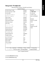
BIOS Setup English Integrated Peripherals CMOS Setup Utility -Copy right (C) 1984-2003 Aw ard Softw are On-Chip Primary PCI IDE On-Chip Secondary PCI IDE .../PD:Value F10:Sav e ESC:Ex it F1:General Help * F 3 : L a n g u a g e ( ) F5:Prev ious Values F6:Fail-Safe Defaults F7:Optimized Defaults Figure 4: Integrated Peripherals (*) For GA-8IPE1000 Pro-G only. (u) For GA-8IPE1000-G only. - 43 -
BIOS Setup English Integrated Peripherals CMOS Setup Utility -Copy right (C) 1984-2003 Aw ard Softw are On-Chip Primary PCI IDE On-Chip Secondary PCI IDE .../PD:Value F10:Sav e ESC:Ex it F1:General Help * F 3 : L a n g u a g e ( ) F5:Prev ious Values F6:Fail-Safe Defaults F7:Optimized Defaults Figure 4: Integrated Peripherals (*) For GA-8IPE1000 Pro-G only. (u) For GA-8IPE1000-G only. - 43 -

User Manual
Page 49
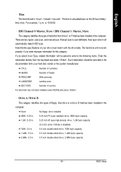
... is 3F8. (Default v alue) 2F8/IRQ3 Enable onboard Serial port 1 and address is 2F8. 3E8/IRQ4 Enable onboard Serial port 1 and address is 3E8. (*) For GA-8IPE1000 Pro-G only. (u) For GA-8IPE1000-G only. - 45 - BIOS Setup English USB 2.0 Controller Disable this function. USB Keyboard Support Enabled Enable USB Key board Support.
... is 3F8. (Default v alue) 2F8/IRQ3 Enable onboard Serial port 1 and address is 2F8. 3E8/IRQ4 Enable onboard Serial port 1 and address is 3E8. (*) For GA-8IPE1000 Pro-G only. (u) For GA-8IPE1000-G only. - 45 - BIOS Setup English USB 2.0 Controller Disable this function. USB Keyboard Support Enabled Enable USB Key board Support.


