Manual
Page 4
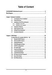
...GA-8I945GMF Motherboard Layout 6 Block Diagram ...7 Chapter 1 Hardware Installation 9 1-1 Considerations Prior to Installation 9 1-2 Feature Summary 10 1-3 Installation of the CPU and Heatsink 12 1-3-1 Installation of the CPU 12 1-3-2 Installation of the Heatsink 13 1-4 Installation of Memory 14 1-5 Install expansion cards 16 1-6 I/O Back Panel Introduction 17 1-7 Connectors Introduction 18 Chapter 2 BIOS... Setup 29 The Main Menu (For example: BIOS Ver. : F2 30 2-1 Standard CMOS Features 32 2-2 Advanced BIOS Features 35 2-3 IntegratedPeripherals ...
...GA-8I945GMF Motherboard Layout 6 Block Diagram ...7 Chapter 1 Hardware Installation 9 1-1 Considerations Prior to Installation 9 1-2 Feature Summary 10 1-3 Installation of the CPU and Heatsink 12 1-3-1 Installation of the CPU 12 1-3-2 Installation of the Heatsink 13 1-4 Installation of Memory 14 1-5 Install expansion cards 16 1-6 I/O Back Panel Introduction 17 1-7 Connectors Introduction 18 Chapter 2 BIOS... Setup 29 The Main Menu (For example: BIOS Ver. : F2 30 2-1 Standard CMOS Features 32 2-2 Advanced BIOS Features 35 2-3 IntegratedPeripherals ...
Manual
Page 5
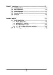
Chapter 3 Install Drivers 51 3-1 Install Chipset Drivers 51 3-2 SoftwareApplications 52 3-3 Driver CD Information 52 3-4 Hardware Information 53 3-5 Contact Us ...53 Chapter 4 Appendix 55 4-1 Unique Software Utilities 55 4-1-1 EasyTune 5 Introduction 56 4-1-2 Xpress Recovery2 Introduction 57 4-1-3 Flash BIOS Method Introduction 60 4-1-4 2- / 4- / 6- / 8- Channel Audio Function Introduction 69 4-2 Troubleshooting 73 - 5 -
Chapter 3 Install Drivers 51 3-1 Install Chipset Drivers 51 3-2 SoftwareApplications 52 3-3 Driver CD Information 52 3-4 Hardware Information 53 3-5 Contact Us ...53 Chapter 4 Appendix 55 4-1 Unique Software Utilities 55 4-1-1 EasyTune 5 Introduction 56 4-1-2 Xpress Recovery2 Introduction 57 4-1-3 Flash BIOS Method Introduction 60 4-1-4 2- / 4- / 6- / 8- Channel Audio Function Introduction 69 4-2 Troubleshooting 73 - 5 -
Manual
Page 6
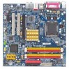
GA-8I945GMF Motherboard Layout COMA LPT KB_MS ATX_12V LGA775 CPU_FAN IT8712F RF_ID ATX VGA GA-8I945GMF USB USB 1394 LAN Intel 945G F_AUDIO AUDIO1 AUDIO2 PCIE_16 PCI1 Marvell 8053 PCI2 CD_IN PCIE_1 CODEC SPDIF_IO COMB DDRII1 DDRII2 DDRII3 DDRII4 IDE FDD BIOS SATAII2_3 ICH7 BATTERY TSB43AB23 SATAII0_1 CI SYS_FAN F1_1394 F2_1394 GREEN_USB F_USB CLR_CMOS F_PANEL PWR_LED (Optional) - 6 -
GA-8I945GMF Motherboard Layout COMA LPT KB_MS ATX_12V LGA775 CPU_FAN IT8712F RF_ID ATX VGA GA-8I945GMF USB USB 1394 LAN Intel 945G F_AUDIO AUDIO1 AUDIO2 PCIE_16 PCI1 Marvell 8053 PCI2 CD_IN PCIE_1 CODEC SPDIF_IO COMB DDRII1 DDRII2 DDRII3 DDRII4 IDE FDD BIOS SATAII2_3 ICH7 BATTERY TSB43AB23 SATAII0_1 CI SYS_FAN F1_1394 F2_1394 GREEN_USB F_USB CLR_CMOS F_PANEL PWR_LED (Optional) - 6 -
Manual
Page 7
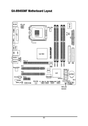
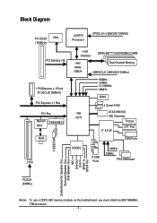
.../200/133MHz) Host Interface DDRII 667(Note)/533/400MHz DIMM Intel 945G GMCH Dual Channel Memory GMCHCLK (266/200/133MHz) 66MHz 33MHz 14.318MHz 48MHz BIOS 4 Serial ATAII Intel ATA33/66/100 ICH7 IDE Channels Floppy IT 8712F LPT Port COM Ports 3 IEEE1394 2 PCI CODEC 8 USB Ports 24MHz 33MHz PS/2 KB...
.../200/133MHz) Host Interface DDRII 667(Note)/533/400MHz DIMM Intel 945G GMCH Dual Channel Memory GMCHCLK (266/200/133MHz) 66MHz 33MHz 14.318MHz 48MHz BIOS 4 Serial ATAII Intel ATA33/66/100 ICH7 IDE Channels Floppy IT 8712F LPT Port COM Ports 3 IEEE1394 2 PCI CODEC 8 USB Ports 24MHz 33MHz PS/2 KB...
Manual
Page 11
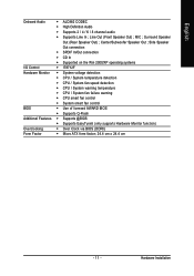
... fan failure warning Š CPU smart fan control Š System smart fan control BIOS Š Use of licensed AWARD BIOS Š Supports Q-Flash Additional Features Š Supports @BIOS Š Supports EasyTune5 (only supports Hardware Monitor function) Overclocking Š Over Clock via BIOS (DDRII) Form Factor Š Micro ATX form factor; 24.4 cm x 24.4 cm...
... fan failure warning Š CPU smart fan control Š System smart fan control BIOS Š Use of licensed AWARD BIOS Š Supports Q-Flash Additional Features Š Supports @BIOS Š Supports EasyTune5 (only supports Hardware Monitor function) Overclocking Š Over Clock via BIOS (DDRII) Form Factor Š Micro ATX form factor; 24.4 cm x 24.4 cm...
Manual
Page 12
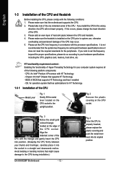
... Metal Lever Fig. 1 Gently lift the metal lever located on the CPU prior to the CPU during installation.) GA-8I945GMF Motherboard - 12 - Chipset: An Intel® Chipset that supports HT Technology and has it enabled - BIOS: A BIOS that supports HT Technology - HT functionality requirement content : Enabling the functionality of Hyper-Threading Technology for the...
... Metal Lever Fig. 1 Gently lift the metal lever located on the CPU prior to the CPU during installation.) GA-8I945GMF Motherboard - 12 - Chipset: An Intel® Chipset that supports HT Technology and has it enabled - BIOS: A BIOS that supports HT Technology - HT functionality requirement content : Enabling the functionality of Hyper-Threading Technology for the...
Manual
Page 14
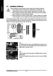
...inserted only in one direction. Insert the DIMM memory module vertically into the DIMM socket. Memory modules have a foolproof insertion design. GA-8I945GMF Motherboard - 14 - English 1-4 Installation of Memory Before installing the memory modules, please comply with each slot. Before installing or... removing memory modules, please make sure that the memory used . 2. The motherboard supports DDR II memory modules, whereby BIOS will automatically detect memory capacity and specifications. Reverse the installation steps when you are designed so that the computer power is...
...inserted only in one direction. Insert the DIMM memory module vertically into the DIMM socket. Memory modules have a foolproof insertion design. GA-8I945GMF Motherboard - 14 - English 1-4 Installation of Memory Before installing the memory modules, please comply with each slot. Before installing or... removing memory modules, please make sure that the memory used . 2. The motherboard supports DDR II memory modules, whereby BIOS will automatically detect memory capacity and specifications. Reverse the installation steps when you are designed so that the computer power is...
Manual
Page 15
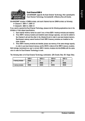
...in order to use dual channel memory and for BIOS to detect all the DDR II memory modules. We'll strongly recommend our user to slot two DDR II memory modules into the DIMMs with the same color in order to work. GA-8I945GMF includes 4 DIMM sockets, and each Channel has...the Dual Channel Technology, please note the following table is for Dual Channel Technology to use dual channel memory. English Dual Channel DDR II GA-8I945GMF supports the Dual Channel Technology. Dual channel memory cannot function if both DDR II memory modules are installed (same storage capacity), one or ...
...in order to use dual channel memory and for BIOS to detect all the DDR II memory modules. We'll strongly recommend our user to slot two DDR II memory modules into the DIMMs with the same color in order to work. GA-8I945GMF includes 4 DIMM sockets, and each Channel has...the Dual Channel Technology, please note the following table is for Dual Channel Technology to use dual channel memory. English Dual Channel DDR II GA-8I945GMF supports the Dual Channel Technology. Dual channel memory cannot function if both DDR II memory modules are installed (same storage capacity), one or ...
Manual
Page 16
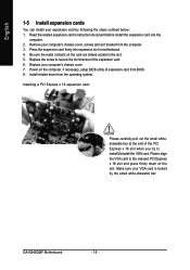
... x 16 slot when you try to secure the slot bracket of expansion card from BIOS. 8. Install related driver from the computer. 3. Be sure the metal contacts on the computer, if necessary, setup BIOS utility of the expansion card. 6. GA-8I945GMF Motherboard - 16 - Remove your computer's chassis cover, screws and slot bracket from the operating...
... x 16 slot when you try to secure the slot bracket of expansion card from BIOS. 8. Install related driver from the computer. 3. Be sure the metal contacts on the computer, if necessary, setup BIOS utility of the expansion card. 6. GA-8I945GMF Motherboard - 16 - Remove your computer's chassis cover, screws and slot bracket from the operating...
Manual
Page 21
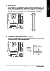
... 1 GND 7 1 2 TXP 3 TXN 1 7 4 GND 5 RXN 6 RXP 7 GND - 21 - English 6) IDE (IDE Connector) An IDE device connects to work properly. Pin No. Please refer to the BIOS setting for information on settings, please refer to the instructions located on the IDE device). 40 39 2 1 7) SATAII0/SATAII1/SATAII2/SATAII3 (SATA 3Gb/s Connector) SATA...
... 1 GND 7 1 2 TXP 3 TXN 1 7 4 GND 5 RXN 6 RXP 7 GND - 21 - English 6) IDE (IDE Connector) An IDE device connects to work properly. Pin No. Please refer to the BIOS setting for information on settings, please refer to the instructions located on the IDE device). 40 39 2 1 7) SATAII0/SATAII1/SATAII2/SATAII3 (SATA 3Gb/s Connector) SATA...
Manual
Page 26
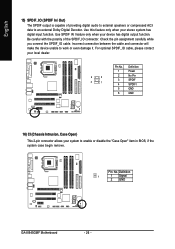
Check the pin assignment carefully while you connect the SPDIF_IO cable. Definition 1 1 Signal 2 GND GA-8I945GMF Motherboard - 26 - Incorrect connection between the cable and connector will make the device unable to enable or disable the "Case Open" item in BIOS, if the system case begin remove. Be careful with the polarity of providing digital...
Check the pin assignment carefully while you connect the SPDIF_IO cable. Definition 1 1 Signal 2 GND GA-8I945GMF Motherboard - 26 - Incorrect connection between the cable and connector will make the device unable to enable or disable the "Case Open" item in BIOS, if the system case begin remove. Be careful with the polarity of providing digital...
Manual
Page 29
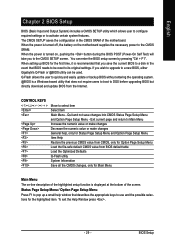
Quit and not save the current BIOS to a new BIOS, either Gigabyte's Q-Flash or @BIOS utility can enter the BIOS setup screen by pressing "Ctrl + F1". To exit the Help Window press . - 29 - BIOS Setup English Chapter 2 BIOS Setup BIOS (Basic Input and Output System) includes a CMOS SETUP utility which allows user to configure ...Q-Flash utility System Information Save all the CMOS changes, only for the first time, it is turned on, pushing the button during the BIOS POST (Power-On Self Test) will take you wish to upgrade to a disk in the CMOS SRAM of the screen. When the ...
Quit and not save the current BIOS to a new BIOS, either Gigabyte's Q-Flash or @BIOS utility can enter the BIOS setup screen by pressing "Ctrl + F1". To exit the Help Window press . - 29 - BIOS Setup English Chapter 2 BIOS Setup BIOS (Basic Input and Output System) includes a CMOS SETUP utility which allows user to configure ...Q-Flash utility System Information Save all the CMOS changes, only for the first time, it is turned on, pushing the button during the BIOS POST (Power-On Self Test) will take you wish to upgrade to a disk in the CMOS SRAM of the screen. When the ...
Manual
Page 30
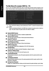
... system reset to the default for stability. „ Standard CMOS Features This setup page includes all the items in standard compatible BIOS. „ Advanced BIOS Features This setup page includes all the items of Award special enhanced features. „ Integrated Peripherals This setup page includes all...Password Change, set, or disable password. If you can't find the setting you enter Award BIOS CMOS Setup Utility, the Main Menu (as usual. GA-8I945GMF Motherboard - 30 - English The Main Menu (For example: BIOS Ver. : F2) Once you want, please press "Ctrl+F1" to search the advanced...
... system reset to the default for stability. „ Standard CMOS Features This setup page includes all the items in standard compatible BIOS. „ Advanced BIOS Features This setup page includes all the items of Award special enhanced features. „ Integrated Peripherals This setup page includes all...Password Change, set, or disable password. If you can't find the setting you enter Award BIOS CMOS Setup Utility, the Main Menu (as usual. GA-8I945GMF Motherboard - 30 - English The Main Menu (For example: BIOS Ver. : F2) Once you want, please press "Ctrl+F1" to search the advanced...

Manual
Page 31
BIOS Setup English „ Set User Password Change, set, or disable password. It allows you to limit access to the system. „ Save & Exit Setup Save CMOS value settings to CMOS and exit setup. „ Exit Without Saving Abandon all CMOS value changes and exit setup. - 31 -
BIOS Setup English „ Set User Password Change, set, or disable password. It allows you to limit access to the system. „ Save & Exit Setup Save CMOS value settings to CMOS and exit setup. „ Exit Without Saving Abandon all CMOS value changes and exit setup. - 31 -
Manual
Page 32
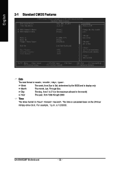
...format in the month) < Ye a r > 1999 to 31 (or maximum allowed in . Through Dec. The time is , , , . to Sat, determined by the BIOS and is 13:00:00. to Dec. 1 to 2098 KLJI: Move Enter: Select F5: Previous Values +/-/PU/PD: Value F10: Save F6: Fail-Save Default... Drive A Drive B Floppy 3 Mode Suport Holt On Base Memory Extended Memory Total Memory [1.44M, 3.5"] [None] [Disabled] [All, But Keyboard] 640K 127M 128M Sun. GA-8I945GMF Motherboard - 32 - For example, 1 p.m. Day The day, from 1 to 31 (or the maximum allowed in the month) Year The year, from Sun to Sat.
...format in the month) < Ye a r > 1999 to 31 (or maximum allowed in . Through Dec. The time is , , , . to Sat, determined by the BIOS and is 13:00:00. to Dec. 1 to 2098 KLJI: Move Enter: Select F5: Previous Values +/-/PU/PD: Value F10: Save F6: Fail-Save Default... Drive A Drive B Floppy 3 Mode Suport Holt On Base Memory Extended Memory Total Memory [1.44M, 3.5"] [None] [Disabled] [All, But Keyboard] 640K 127M 128M Sun. GA-8I945GMF Motherboard - 32 - For example, 1 p.m. Day The day, from 1 to 31 (or the maximum allowed in the month) Year The year, from Sun to Sat.
Manual
Page 33
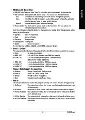
... byte capacity 1.44M, 3.5" 3.5 inch double-sided drive; 1.44M byte capacity. 2.88M, 3.5" 3.5 inch double-sided drive; 2.88M byte capacity. BIOS Setup Halt on The category determines whether the computer will skip the automatic detection step and allow for the hard drive. All Errors Whenever the... BIOS detects a non-fatal error the system will stop for all other errors. it will be labeled on this information. Drive ...
... byte capacity 1.44M, 3.5" 3.5 inch double-sided drive; 1.44M byte capacity. 2.88M, 3.5" 3.5 inch double-sided drive; 2.88M byte capacity. BIOS Setup Halt on The category determines whether the computer will skip the automatic detection step and allow for the hard drive. All Errors Whenever the... BIOS detects a non-fatal error the system will stop for all other errors. it will be labeled on this information. Drive ...
Manual
Page 34
GA-8I945GMF Motherboard - 34 - Base Memory The POST of the BIOS will determine the amount of the base memory is present during the POST. This is determined by POST (Power On Self Test) of the BIOS. English Memory The category is display-only which is the amount of memory located above 1 MB in the system.... Extended Memory The BIOS determines how much extended memory is typically 512K for systems with 512K memory installed on the motherboard, or 640K for systems with 640K or more ...
GA-8I945GMF Motherboard - 34 - Base Memory The POST of the BIOS will determine the amount of the base memory is present during the POST. This is determined by POST (Power On Self Test) of the BIOS. English Memory The category is display-only which is the amount of memory located above 1 MB in the system.... Extended Memory The BIOS determines how much extended memory is typically 512K for systems with 512K memory installed on the motherboard, or 640K for systems with 640K or more ...
Manual
Page 35
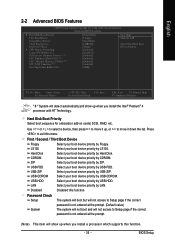
... processor with HT Technology. USB-FDD Select your boot device priority by USB-FDD. LAN Select your boot device priority by LAN. BIOS Setup LS120 Select your boot device priority by LS120. Password Check Setup System The system will boot but will not access to Setup ... This item will detect automatically and show up , or to move it down the list. English 2-2 Advanced BIOS Features CMOS Setup Utility-Copyright (C) 1984-2005 Award Software Advanced BIOS Features ` Hard Disk Boot Priority First Boot Device Second Boot Device Third Boot Device Password Check # CPU Hyper...
... processor with HT Technology. USB-FDD Select your boot device priority by USB-FDD. LAN Select your boot device priority by LAN. BIOS Setup LS120 Select your boot device priority by LS120. Password Check Setup System The system will boot but will not access to Setup ... This item will detect automatically and show up , or to move it down the list. English 2-2 Advanced BIOS Features CMOS Setup Utility-Copyright (C) 1984-2005 Award Software Advanced BIOS Features ` Hard Disk Boot Priority First Boot Device Second Boot Device Third Boot Device Password Check # CPU Hyper...
Manual
Page 37
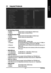
...Set On-Chip SATA mode to Non-Combined, SATA will auto detect. (Default value) Set On-Chip SATA mode to Combined, you can use . BIOS will be simulated to 4 HDDs on the motherboard; 2 for SATA and the other for PATA IDE. SATA Port 1/3 Set to This value will ...SATA Mode" and "PATA IDE Set to Ch. 0 Master/Slave. USB Controller Enabled Enable USB Controller. (Default value) Disabled Disable USB Controller. - 37 - BIOS Setup On-Chip Secondary PCI IDE Enabled Enable onboard 2nd channel IDE port. (Default value) Disabled Disable onboard 2nd channel IDE port. If PATA IDE...
...Set On-Chip SATA mode to Non-Combined, SATA will auto detect. (Default value) Set On-Chip SATA mode to Combined, you can use . BIOS will be simulated to 4 HDDs on the motherboard; 2 for SATA and the other for PATA IDE. SATA Port 1/3 Set to This value will ...SATA Mode" and "PATA IDE Set to Ch. 0 Master/Slave. USB Controller Enabled Enable USB Controller. (Default value) Disabled Disable USB Controller. - 37 - BIOS Setup On-Chip Secondary PCI IDE Enabled Enable onboard 2nd channel IDE port. (Default value) Disabled Disable onboard 2nd channel IDE port. If PATA IDE...
Manual
Page 38
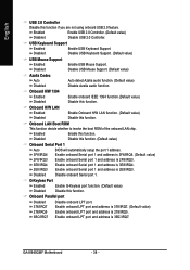
...function. Disabled Disable onboard Serial port 1. G-Keyless Port Enabled Enable G-Keyless port function. (Default value) Disabled Disable this function. GA-8I945GMF Motherboard - 38 - Enabled Disabled Enable this function if you are not using onboard USB 2.0 feature. Enable onboard LPT port ... H/W LAN Enabled Enable Onboard H/W LAN function. (Default value) Disabled Disable this function. (Default value) Onboard Serial Port 1 Auto BIOS will automatically setup the port 1 address. 3F8/IRQ4 2F8/IRQ3 Enable onboard Serial port 1 and address is 3F8/IRQ4. (Default value...
...function. Disabled Disable onboard Serial port 1. G-Keyless Port Enabled Enable G-Keyless port function. (Default value) Disabled Disable this function. GA-8I945GMF Motherboard - 38 - Enabled Disabled Enable this function if you are not using onboard USB 2.0 feature. Enable onboard LPT port ... H/W LAN Enabled Enable Onboard H/W LAN function. (Default value) Disabled Disable this function. (Default value) Onboard Serial Port 1 Auto BIOS will automatically setup the port 1 address. 3F8/IRQ4 2F8/IRQ3 Enable onboard Serial port 1 and address is 3F8/IRQ4. (Default value...


