Manual
Page 1
GA-8I915P Dual Graphic Intel® Pentium® 4 LGA775 Processor Motherboard User's Manual Rev. 1002 12ME-8I915PDG-1002
GA-8I915P Dual Graphic Intel® Pentium® 4 LGA775 Processor Motherboard User's Manual Rev. 1002 12ME-8I915PDG-1002

Manual
Page 2
Motherboard GA-8I915P Dual Graphic Jan. 13, 2005 Motherboard GA-8I915P Dual Graphic Jan. 13, 2005
Motherboard GA-8I915P Dual Graphic Jan. 13, 2005 Motherboard GA-8I915P Dual Graphic Jan. 13, 2005
Manual
Page 4
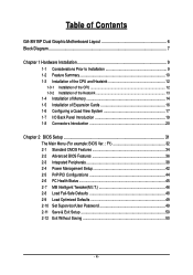
Table of Contents GA-8I915P Dual Graphic Motherboard Layout 6 Block Diagram ...7 Chapter 1 Hardware Installation 9 1-1 Considerations Prior to Installation 9 1-2 Feature Summary 10 1-3 Installation of the CPU and Heatsink 12 1-3-1 Installation of the CPU ...
Table of Contents GA-8I915P Dual Graphic Motherboard Layout 6 Block Diagram ...7 Chapter 1 Hardware Installation 9 1-1 Considerations Prior to Installation 9 1-2 Feature Summary 10 1-3 Installation of the CPU and Heatsink 12 1-3-1 Installation of the CPU ...

Manual
Page 6
GA-8I915P Dual Graphic Motherboard Layout DDRII_1 DDR1 DDRII_2 DDR2 PWR_FAN KB_MS ATX_12V LGA775 ATX SPDIF_O SPDIF_I CPU_FAN LPT COMA GA-8I915P Dual Graphic IDE1 R_USB LAN USB AUDIO1 AUDIO2 CD_IN BAT AZALIA_FP Marvell 8001 PCIE_1 SW1 NB_FAN Backup Main BIOS BIOS Intel 915P PCIE_16_1 PCIE_16_2 FDD SYS_FAN ICH6R CLR_CMOS CODEC IT8712 F_USB2 PCI1 SATA3 F_PANEL F_USB1 PCI2 VT6410 TSB43AB23 PCI3 IDE3 F1_1394 IDE2 IR F2_1394 SATA2 SATA1 PWR_LED SATA0 - 6 -
GA-8I915P Dual Graphic Motherboard Layout DDRII_1 DDR1 DDRII_2 DDR2 PWR_FAN KB_MS ATX_12V LGA775 ATX SPDIF_O SPDIF_I CPU_FAN LPT COMA GA-8I915P Dual Graphic IDE1 R_USB LAN USB AUDIO1 AUDIO2 CD_IN BAT AZALIA_FP Marvell 8001 PCIE_1 SW1 NB_FAN Backup Main BIOS BIOS Intel 915P PCIE_16_1 PCIE_16_2 FDD SYS_FAN ICH6R CLR_CMOS CODEC IT8712 F_USB2 PCI1 SATA3 F_PANEL F_USB1 PCI2 VT6410 TSB43AB23 PCI3 IDE3 F1_1394 IDE2 IR F2_1394 SATA2 SATA1 PWR_LED SATA0 - 6 -
Manual
Page 10
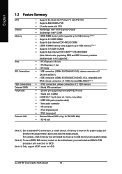
... ICH6R Š 2 DDR DIMM memory slots (supports up to 4GB memory) (Note 1) Š Supports 2.5V DDR DIMM Š Supports dual channel DDR 400/333 DIMM Š 2 DDR II DIMM memory slots (supports up to 4GB memory) (Note 1) Š Supports 1.8V... DDR II DIMM Š Supports dual channel DDR II 600(Note 2)/533/400 DIMM (Note: Mixed mode, populating DDR and DDR II memory modules simultaneously is not supported.... For example, 4 GB of memory is less than the stated amount. GA-8I915P Dual Graphic Motherboard - 10 -
... ICH6R Š 2 DDR DIMM memory slots (supports up to 4GB memory) (Note 1) Š Supports 2.5V DDR DIMM Š Supports dual channel DDR 400/333 DIMM Š 2 DDR II DIMM memory slots (supports up to 4GB memory) (Note 1) Š Supports 1.8V... DDR II DIMM Š Supports dual channel DDR II 600(Note 2)/533/400 DIMM (Note: Mixed mode, populating DDR and DDR II memory modules simultaneously is not supported.... For example, 4 GB of memory is less than the stated amount. GA-8I915P Dual Graphic Motherboard - 10 -
Manual
Page 12
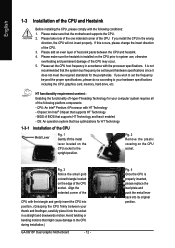
...wrong direction, the CPU will not insert properly. Fig. 2 Remove the plastic covering on the CPU socket to the CPU during installation.) GA-8I915P Dual Graphic Motherboard - 12 - Fig. 4 Once the CPU is installed on the edge of the CPU socket. BIOS: A BIOS that the motherboard...socket in a straight and downwards motion. Chipset: An Intel® Chipset that has optimizations for your hardware specifications including the CPU, graphics card, memory, hard drive, etc. OS: An operation system that supports HT Technology - English 1-3 Installation of the CPU and Heatsink...
...wrong direction, the CPU will not insert properly. Fig. 2 Remove the plastic covering on the CPU socket to the CPU during installation.) GA-8I915P Dual Graphic Motherboard - 12 - Fig. 4 Once the CPU is installed on the edge of the CPU socket. BIOS: A BIOS that the motherboard...socket in a straight and downwards motion. Chipset: An Intel® Chipset that has optimizations for your hardware specifications including the CPU, graphics card, memory, hard drive, etc. OS: An operation system that supports HT Technology - English 1-3 Installation of the CPU and Heatsink...

Manual
Page 14
..., please comply with each slot. If you wish to lock the DIMM module. A memory module can be used can only fit in only one direction. GA-8I915P Dual Graphic Motherboard - 14 - Please make sure that the memory used is switched off to insert the module, please switch the direction. Before installing or removing memory...
..., please comply with each slot. If you wish to lock the DIMM module. A memory module can be used can only fit in only one direction. GA-8I915P Dual Graphic Motherboard - 14 - Please make sure that the memory used is switched off to insert the module, please switch the direction. Before installing or removing memory...

Manual
Page 15
...(it is recommended to operate the Dual Channel Technology, please follow the guidelines below for Dual Channel memory configuration. 1. When the Dual Channel Technology is activated, the bandwidth of the same color. English Dual Channel DDR/DDR II The GA-8I915P Dual Graphic supports the Dual Channel Technology. Hardware Installation The following is a Dual Channel Memory configuration table: (DS:... them into DIMM sockets of memory bus will not be double the original one DDR/DDR II memory module is not supported. - 15 - Dual Channel mode will be enabled if only one .
...(it is recommended to operate the Dual Channel Technology, please follow the guidelines below for Dual Channel memory configuration. 1. When the Dual Channel Technology is activated, the bandwidth of the same color. English Dual Channel DDR/DDR II The GA-8I915P Dual Graphic supports the Dual Channel Technology. Hardware Installation The following is a Dual Channel Memory configuration table: (DS:... them into DIMM sockets of memory bus will not be double the original one DDR/DDR II memory module is not supported. - 15 - Dual Channel mode will be enabled if only one .
Manual
Page 16
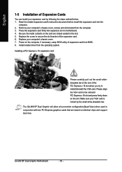
.... 2. Replace your computer's chassis cover. 7. Power on the slot .Make sure your VGA card is locked by following the steps outlined below: 1. GA-8I915P Dual Graphic Motherboard - 16 - Install related driver from the computer. 3. Installing a PCI Express x 16 expansion card: Please carefully pull out the small whitedrawable bar... slot. 5. English 1-5 Installation of Expansion Cards You can install your expansion card by the small white-drawable bar. The GA-8I915P Dual Graphic will allow a four-monitor configuration(Quad View) when used in conjunction with two PCI Express...
.... 2. Replace your computer's chassis cover. 7. Power on the slot .Make sure your VGA card is locked by following the steps outlined below: 1. GA-8I915P Dual Graphic Motherboard - 16 - Install related driver from the computer. 3. Installing a PCI Express x 16 expansion card: Please carefully pull out the small whitedrawable bar... slot. 5. English 1-5 Installation of Expansion Cards You can install your expansion card by the small white-drawable bar. The GA-8I915P Dual Graphic will allow a four-monitor configuration(Quad View) when used in conjunction with two PCI Express...
Manual
Page 18
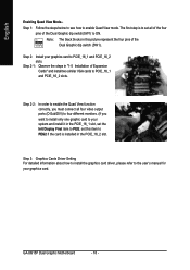
GA-8I915P Dual Graphic Motherboard - 18 - Step 2-2: In order to enable the Quad View function correctly, you must connect all of the four pins of the Dual Graphic dip switch(SW1) to PEG; Step 3: Graphics Cards Driver Setting For detailed information about how to install the graphics card driver, please refer ... set the Init Display First item to ON. The first step is installed in "1-5 Installation of the Dual Graphic dip switch (SW1). 1 234 Step 2: Install your graphics card to PCIE_16_1 and PCIE_16_2 slots. English Enabling Quad View Mode-Step 1: Follow the steps below to ...
GA-8I915P Dual Graphic Motherboard - 18 - Step 2-2: In order to enable the Quad View function correctly, you must connect all of the four pins of the Dual Graphic dip switch(SW1) to PEG; Step 3: Graphics Cards Driver Setting For detailed information about how to install the graphics card driver, please refer ... set the Init Display First item to ON. The first step is installed in "1-5 Installation of the Dual Graphic dip switch (SW1). 1 234 Step 2: Install your graphics card to PCIE_16_1 and PCIE_16_2 slots. English Enabling Quad View Mode-Step 1: Follow the steps below to ...

Manual
Page 20
... 9 17 16 10 11) PWR_LED 12) F_PANEL 13) AZALIA_FP 14) CD_IN 15) F_USB1 / F_USB2 16) F1_1394 / F2_1394 17) IR 18) CLR_CMOS 19) BAT 20) SW1 GA-8I915P Dual Graphic Motherboard - 20 - You can use audio software to this connector. Surround Speaker Out Connect the surround channels to this connector.
... 9 17 16 10 11) PWR_LED 12) F_PANEL 13) AZALIA_FP 14) CD_IN 15) F_USB1 / F_USB2 16) F1_1394 / F2_1394 17) IR 18) CLR_CMOS 19) BAT 20) SW1 GA-8I915P Dual Graphic Motherboard - 20 - You can use audio software to this connector. Surround Speaker Out Connect the surround channels to this connector.

Manual
Page 22
.... 1 CPU_FAN 1 PWR_FAN 1 SYS_FAN Pin No. 1 2 3 4 Definition GND +12V Sense Speed Control (Only for CPU_FAN) power connector and possesses a foolproof connection design. Caution! Definition 1 1 +12V 2 GND GA-8I915P Dual Graphic Motherboard - 22 - English 3/4/5) CPU_FAN / SYS_FAN / PWR_FAN (Cooler Fan Power Connector) The cooler fan power connector supplies a +12V power voltage via a 3-pin/4-pin (only for CPU_FAN...
.... 1 CPU_FAN 1 PWR_FAN 1 SYS_FAN Pin No. 1 2 3 4 Definition GND +12V Sense Speed Control (Only for CPU_FAN) power connector and possesses a foolproof connection design. Caution! Definition 1 1 +12V 2 GND GA-8I915P Dual Graphic Motherboard - 22 - English 3/4/5) CPU_FAN / SYS_FAN / PWR_FAN (Cooler Fan Power Connector) The cooler fan power connector supplies a +12V power voltage via a 3-pin/4-pin (only for CPU_FAN...
Manual
Page 24
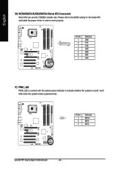
English 10) SATA0/SATA1/SATA2/SATA3 (Serial ATA Connector) Serial ATA can provide 150MB/s transfer rate. Definition 1 1 MPD+ 2 MPD- 3 MPD- Definition 1 GND 7 1 2 TXP 3 TXN 4 GND 5 RXN 6 RXP 7 GND 11) PWR_LED PWR_LED is on/off. It will blink when the system enters suspend mode. Pin No. Please refer to the BIOS setting for the Serial ATA and install the proper driver in order to indicate whether the system is connect with the system power indicator to work properly. GA-8I915P Dual Graphic Motherboard - 24 - Pin No.
English 10) SATA0/SATA1/SATA2/SATA3 (Serial ATA Connector) Serial ATA can provide 150MB/s transfer rate. Definition 1 1 MPD+ 2 MPD- 3 MPD- Definition 1 GND 7 1 2 TXP 3 TXN 4 GND 5 RXN 6 RXP 7 GND 11) PWR_LED PWR_LED is on/off. It will blink when the system enters suspend mode. Pin No. Please refer to the BIOS setting for the Serial ATA and install the proper driver in order to indicate whether the system is connect with the system power indicator to work properly. GA-8I915P Dual Graphic Motherboard - 24 - Pin No.

Manual
Page 26
... 5 Line Out (R) 6 NC 7 NC 8 No Pin 9 Line Out (L) 10 NC HD Audio is supported to work or even damage it. Definition 1 1 CD-L 2 GND 3 GND 4 CD-R GA-8I915P Dual Graphic Motherboard - 26 - English 13) AZALIA_FP(Front Audio Panel Connector) This connector is the default setting for this connector. Check the pin assignment carefully while you...
... 5 Line Out (R) 6 NC 7 NC 8 No Pin 9 Line Out (L) 10 NC HD Audio is supported to work or even damage it. Definition 1 1 CD-L 2 GND 3 GND 4 CD-R GA-8I915P Dual Graphic Motherboard - 26 - English 13) AZALIA_FP(Front Audio Panel Connector) This connector is the default setting for this connector. Check the pin assignment carefully while you...

Manual
Page 28
Definition 1 Power 2 No Pin 1 3 IR RX 4 GND 5 IR TX 18) CLR_CMOS (Clear CMOS) You may clear the CMOS data to prevent from improper use this jumper. To clear CMOS, temporarily short 1-2 pin. Please contact your nearest dealer for optional IR device. Pin No. Default doesn't include the "Shunter" to its default values by this jumper. 1 Open: Normal 1 Short: Clear CMOS GA-8I915P Dual Graphic Motherboard - 28 - English 17) IR Be careful with the polarity of the IR connector while you connect the IR.
Definition 1 Power 2 No Pin 1 3 IR RX 4 GND 5 IR TX 18) CLR_CMOS (Clear CMOS) You may clear the CMOS data to prevent from improper use this jumper. To clear CMOS, temporarily short 1-2 pin. Please contact your nearest dealer for optional IR device. Pin No. Default doesn't include the "Shunter" to its default values by this jumper. 1 Open: Normal 1 Short: Clear CMOS GA-8I915P Dual Graphic Motherboard - 28 - English 17) IR Be careful with the polarity of the IR connector while you connect the IR.

Manual
Page 30
English GA-8I915P Dual Graphic Motherboard - 30 -
English GA-8I915P Dual Graphic Motherboard - 30 -

Manual
Page 32
GA-8I915P Dual Graphic Motherboard - 32 - CMOS Setup Utility-Copyright (C) 1984-2004 Award Software ` Standard CMOS Features ` Advanced BIOS Features ` Integrated Peripherals ` Power Management Setup ` PnP/PCI Configurations ` PC ... ISA resources. „ PC Health Status This setup page is the System auto detect Temperature, voltage, fan, speed. „ MB Intelligent Tweaker(M.I .T.) ESC: Quit F8: Dual BIOS/Q-Flash Load Fail-Safe Defaults Load Optimized Defaults Set Supervisor Password Set User Password Save & Exit Setup Exit Without Saving KLJI: Select Item F10...
GA-8I915P Dual Graphic Motherboard - 32 - CMOS Setup Utility-Copyright (C) 1984-2004 Award Software ` Standard CMOS Features ` Advanced BIOS Features ` Integrated Peripherals ` Power Management Setup ` PnP/PCI Configurations ` PC ... ISA resources. „ PC Health Status This setup page is the System auto detect Temperature, voltage, fan, speed. „ MB Intelligent Tweaker(M.I .T.) ESC: Quit F8: Dual BIOS/Q-Flash Load Fail-Safe Defaults Load Optimized Defaults Set Supervisor Password Set User Password Save & Exit Setup Exit Without Saving KLJI: Select Item F10...
Manual
Page 34
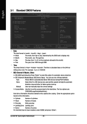
... 24-hour military-time clock. The four options are used and the system will skip the automatic detection step and allow for the hard drive. GA-8I915P Dual Graphic Motherboard - 34 - to 31 (or the maximum allowed in the month) 1999 to set the access mode for faster system start up. English 2-1 Standard CMOS...
... 24-hour military-time clock. The four options are used and the system will skip the automatic detection step and allow for the hard drive. GA-8I915P Dual Graphic Motherboard - 34 - to 31 (or the maximum allowed in the month) 1999 to set the access mode for faster system start up. English 2-1 Standard CMOS...
Manual
Page 36
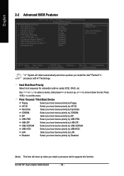
... by ZIP. First / Second / Third Boot Device Floppy Select your boot device priority by USB-FDD. ZIP Select your boot device priority by USB-ZIP. GA-8I915P Dual Graphic Motherboard - 36 - CDROM Select your boot device priority by Floppy. Use < > or < > to select a device, then press to move it up when you install the...
... by ZIP. First / Second / Third Boot Device Floppy Select your boot device priority by USB-FDD. ZIP Select your boot device priority by USB-ZIP. GA-8I915P Dual Graphic Motherboard - 36 - CDROM Select your boot device priority by Floppy. Use < > or < > to select a device, then press to move it up when you install the...

Manual
Page 38
WinXP,2000 only. GA-8I915P Dual Graphic Motherboard - 38 - Disabled Select onboard Seria ATA function as RAID. (Default value) Support hotplug function under OS. English 2-3 Integrated Peripherals CMOS Setup Utility-Copyright (C) 1984-...
WinXP,2000 only. GA-8I915P Dual Graphic Motherboard - 38 - Disabled Select onboard Seria ATA function as RAID. (Default value) Support hotplug function under OS. English 2-3 Integrated Peripherals CMOS Setup Utility-Copyright (C) 1984-...

