
Manual
Page 3
... VT6410 IDE controller mode and boot sequence in system BIOS Setup and set BIOS boot sequence for the IDE RAID hard drive(s). CMOS Setup Utility-Copyright (C) 1984-2004 Award Software Integrated Peripherals On-Chip Primary PCI IDE SATA RAID/AHCI Mode x On-Chip SATA Mode x PATA IDE Set to SATA Port 0/2 Set to SATA Port 1/3 Set to USB Controller USB 2.0 Controller USB Keyboard Support USB Mouse Support Azalia Codec Onboard H/W RAID Onboard H/W 1394 Onboard H/W LAN1 Onboard H/W LAN2 Onboard LAN1 Boot ROM Onboard LAN2 Boot ROM Onboard Serial Port 1 Onboard IrDA Port [Enabled] [RAID] Auto Ch...
... VT6410 IDE controller mode and boot sequence in system BIOS Setup and set BIOS boot sequence for the IDE RAID hard drive(s). CMOS Setup Utility-Copyright (C) 1984-2004 Award Software Integrated Peripherals On-Chip Primary PCI IDE SATA RAID/AHCI Mode x On-Chip SATA Mode x PATA IDE Set to SATA Port 0/2 Set to SATA Port 1/3 Set to USB Controller USB 2.0 Controller USB Keyboard Support USB Mouse Support Azalia Codec Onboard H/W RAID Onboard H/W 1394 Onboard H/W LAN1 Onboard H/W LAN2 Onboard LAN1 Boot ROM Onboard LAN2 Boot ROM Onboard Serial Port 1 Onboard IrDA Port [Enabled] [RAID] Auto Ch...
Manual
Page 10
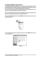
... the IDE RAID controller from the motherboard driver CD to ¤å a floppy disk. Quit the installation utility first. The instructions below explain how to My Computer and right-click the CD-ROM icon (this procedure assumes Drive D) and select Open (Figure 14). First of all, you have to copy the driver for a file named MENU.exe. Ác (4) Making a IDE RAID controller driver disk Åé To install Windows 2000/XP onto a IDE hard disk...
... the IDE RAID controller from the motherboard driver CD to ¤å a floppy disk. Quit the installation utility first. The instructions below explain how to My Computer and right-click the CD-ROM icon (this procedure assumes Drive D) and select Open (Figure 14). First of all, you have to copy the driver for a file named MENU.exe. Ác (4) Making a IDE RAID controller driver disk Åé To install Windows 2000/XP onto a IDE hard disk...
Manual
Page 12
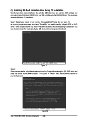
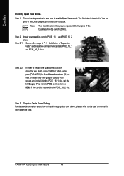
... motherboard. Then you will load support for the following mass storage device(s) * To specify additional SCSI adapters, CD-ROM drives, or special disk controllers for use with the IDE RAID driver. Currently, Setup will be a few moments of one or more mass storage devices installed in your system, or you to manually specify an adapter. This procedure ¤¤ assumes Windows XP installation. ¤å Step 1: Restart your IDE hard disk with Windows, press ENTER...
... motherboard. Then you will load support for the following mass storage device(s) * To specify additional SCSI adapters, CD-ROM drives, or special disk controllers for use with the IDE RAID driver. Currently, Setup will be a few moments of one or more mass storage devices installed in your system, or you to manually specify an adapter. This procedure ¤¤ assumes Windows XP installation. ¤å Step 1: Restart your IDE hard disk with Windows, press ENTER...
Manual
Page 9
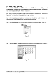
... 11). Quit the installation utility first. Step 1: Find an available system and insert the motherboard driver CD into the CD-ROM drive. Step 2: Go to copy the driver. Figure 11 Step 3: Go to install required driver for the SATA controller during OS installation. Figure 12 SATA Hard Drives Configurations (Intel ICH6R) - 9 - Ác (4) Making a SATA Driver Disk Åé To install Windows 2000/XP onto a SATA hard drives on the ICH6R controller successfully, you need to...
... 11). Quit the installation utility first. Step 1: Find an available system and insert the motherboard driver CD into the CD-ROM drive. Step 2: Go to copy the driver. Figure 11 Step 3: Go to install required driver for the SATA controller during OS installation. Figure 12 SATA Hard Drives Configurations (Intel ICH6R) - 9 - Ác (4) Making a SATA Driver Disk Åé To install Windows 2000/XP onto a SATA hard drives on the ICH6R controller successfully, you need to...
Manual
Page 11
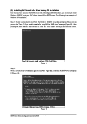
... 1: Restart your SATA hard drive with the SATA driver. The following is an example of some files being loaded before you are ready to install Windows 2000/XP onto your system to boot from the Windows 2000/XP Setup disk and press F6 as soon as you see the next screen. Ác (5) Installing SATA controller driver during OS installation Åé Now that you have prepared the SATA driver disk and configured BIOS settings, you...
... 1: Restart your SATA hard drive with the SATA driver. The following is an example of some files being loaded before you are ready to install Windows 2000/XP onto your system to boot from the Windows 2000/XP Setup disk and press F6 as soon as you see the next screen. Ác (5) Installing SATA controller driver during OS installation Åé Now that you have prepared the SATA driver disk and configured BIOS settings, you...

Manual
Page 11
...Supports ATAPI mode for HDD Š Supports IDE bus master operation Š Displays status and error checking messages during boot-up Š Mirroring supports automatic background rebuilds Š Features LBA and Extended Interrupt 13 drive translation in controller onboard BIOS Š IT8712 Š System voltage detection Š CPU temperature detection Š CPU / System / Power fan speed detection Š CPU warning temperature Š CPU / System / Power fan failure warning Š CPU smart fan control Š Use of licensed AWARD BIOS Š Supports Dual BIOS/Q-Flash Š Supports...
...Supports ATAPI mode for HDD Š Supports IDE bus master operation Š Displays status and error checking messages during boot-up Š Mirroring supports automatic background rebuilds Š Features LBA and Extended Interrupt 13 drive translation in controller onboard BIOS Š IT8712 Š System voltage detection Š CPU temperature detection Š CPU / System / Power fan speed detection Š CPU warning temperature Š CPU / System / Power fan failure warning Š CPU smart fan control Š Use of licensed AWARD BIOS Š Supports Dual BIOS/Q-Flash Š Supports...

Manual
Page 15
... below for Dual Channel memory configuration. 1. To enable Dual Channel mode with 2 memory modules (it is recommended to use memory modules of identical brand, size, chips, and speed), you want to chipset limitation, if you must install them into DIMM sockets of memory bus will not be double the original one DDR/DDR II memory module is not supported. - 15 - English Dual Channel DDR/DDR II The GA-8I915P Dual Graphic supports the Dual Channel Technology. The following is a Dual Channel Memory configuration table: (DS...
... below for Dual Channel memory configuration. 1. To enable Dual Channel mode with 2 memory modules (it is recommended to use memory modules of identical brand, size, chips, and speed), you want to chipset limitation, if you must install them into DIMM sockets of memory bus will not be double the original one DDR/DDR II memory module is not supported. - 15 - English Dual Channel DDR/DDR II The GA-8I915P Dual Graphic supports the Dual Channel Technology. The following is a Dual Channel Memory configuration table: (DS...
Manual
Page 18
... if the card is to set all four video output ports (D-Sub/DVI) to four different monitors. (If you must connect all of the four pins of the Dual Graphic dip switch(SW1) to PCIE_16_1 and PCIE_16_2 slots. set the Init Display First item to the user's manual for your system and install it in the PCIE_16_2 slot. Step 3: Graphics Cards Driver Setting For detailed information about how to install the graphics card driver, please...
... if the card is to set all four video output ports (D-Sub/DVI) to four different monitors. (If you must connect all of the four pins of the Dual Graphic dip switch(SW1) to PCIE_16_1 and PCIE_16_2 slots. set the Init Display First item to the user's manual for your system and install it in the PCIE_16_2 slot. Step 3: Graphics Cards Driver Setting For detailed information about how to install the graphics card driver, please...

Manual
Page 22
...prevent CPU overheating and failure. 1 CPU_FAN 1 PWR_FAN 1 SYS_FAN Pin No. 1 2 3 4 Definition GND +12V Sense Speed Control (Only for CPU_FAN) power connector and possesses a foolproof connection design. Definition 1 1 +12V 2 GND GA-8I915P Dual Graphic Motherboard - 22 - A red power connector wire indicates a positive connection and requires a +12V power voltage. English 3/4/5) CPU_FAN / SYS_FAN / PWR_FAN (Cooler Fan Power Connector) The cooler fan power connector supplies a +12V power voltage via a 3-pin/4-pin (only for CPU_FAN) 6) NB_FAN (Chip Fan Connector) If you installed...
...prevent CPU overheating and failure. 1 CPU_FAN 1 PWR_FAN 1 SYS_FAN Pin No. 1 2 3 4 Definition GND +12V Sense Speed Control (Only for CPU_FAN) power connector and possesses a foolproof connection design. Definition 1 1 +12V 2 GND GA-8I915P Dual Graphic Motherboard - 22 - A red power connector wire indicates a positive connection and requires a +12V power voltage. English 3/4/5) CPU_FAN / SYS_FAN / PWR_FAN (Cooler Fan Power Connector) The cooler fan power connector supplies a +12V power voltage via a 3-pin/4-pin (only for CPU_FAN) 6) NB_FAN (Chip Fan Connector) If you installed...
Manual
Page 24
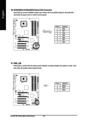
English 10) SATA0/SATA1/SATA2/SATA3 (Serial ATA Connector) Serial ATA can provide 150MB/s transfer rate. Definition 1 1 MPD+ 2 MPD- 3 MPD- GA-8I915P Dual Graphic Motherboard - 24 - Please refer to the BIOS setting for the Serial ATA and install the proper driver in order to indicate whether the system is on/off. Pin No. Pin No. It will blink when the system enters suspend mode. Definition 1 GND 7 1 2 TXP 3 TXN 4 GND 5 RXN 6 RXP 7 GND 11) PWR_LED PWR_LED is connect with the system power indicator to work properly.
English 10) SATA0/SATA1/SATA2/SATA3 (Serial ATA Connector) Serial ATA can provide 150MB/s transfer rate. Definition 1 1 MPD+ 2 MPD- 3 MPD- GA-8I915P Dual Graphic Motherboard - 24 - Please refer to the BIOS setting for the Serial ATA and install the proper driver in order to indicate whether the system is on/off. Pin No. Pin No. It will blink when the system enters suspend mode. Definition 1 GND 7 1 2 TXP 3 TXN 4 GND 5 RXN 6 RXP 7 GND 11) PWR_LED PWR_LED is connect with the system power indicator to work properly.
Manual
Page 34
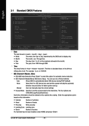
... the hard drive. IDE Channel 0 Master, Slave IDE HDD Auto-Detection Press "Enter" to Sat, determined by the BIOS and is , , , . English 2-1 Standard CMOS Features Date (mm:dd:yy) Time (hh:mm:ss) CMOS Setup Utility-Copyright (C) 1984-2004 Award Software Standard CMOS Features Thu, Dec 7 2004 19:31:24 Item Help Menu Level` ` IDE Channel 0 Master ` IDE Channel 0 Slave [None] [None] Change the day, month, year Drive A Drive B Floppy 3 Mode Suport Halt On [1.44M, 3.5"] [None] [Disabled...
... the hard drive. IDE Channel 0 Master, Slave IDE HDD Auto-Detection Press "Enter" to Sat, determined by the BIOS and is , , , . English 2-1 Standard CMOS Features Date (mm:dd:yy) Time (hh:mm:ss) CMOS Setup Utility-Copyright (C) 1984-2004 Award Software Standard CMOS Features Thu, Dec 7 2004 19:31:24 Item Help Menu Level` ` IDE Channel 0 Master ` IDE Channel 0 Slave [None] [None] Change the day, month, year Drive A Drive B Floppy 3 Mode Suport Halt On [1.44M, 3.5"] [None] [Disabled...
Manual
Page 46
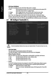
... 2) is not changeable. GA-8I915P Dual Graphic Motherboard - 46 - CPU Clock Ratio This setup option will automatically assign by CPU loading. The option will not effectively reduce the fan speed. 2-7 MB Intelligent Tweaker(M.I.T.) CMOS Setup Utility-Copyright (C) 1984-2004 Award Software MB Intelligent Tweaker(M.I.T.) CPU Clock Ratio Robust Graphics Booster C.I .A.2 to Voltage when you use a CPU fan with a 4-pin fan power cable. English CPU Smart FAN Mode This option is available only when CPU Smart FAN Control is unclocked KLJI: Move Enter: Select F5: Previous Values...
... 2) is not changeable. GA-8I915P Dual Graphic Motherboard - 46 - CPU Clock Ratio This setup option will automatically assign by CPU loading. The option will not effectively reduce the fan speed. 2-7 MB Intelligent Tweaker(M.I.T.) CMOS Setup Utility-Copyright (C) 1984-2004 Award Software MB Intelligent Tweaker(M.I.T.) CPU Clock Ratio Robust Graphics Booster C.I .A.2 to Voltage when you use a CPU fan with a 4-pin fan power cable. English CPU Smart FAN Mode This option is available only when CPU Smart FAN Control is unclocked KLJI: Move Enter: Select F5: Previous Values...

Manual
Page 55
... is disabled, the CPU is a revolutionary eight-phase power circuit built for their BIOS as well as future Intel® processors. With GIGABYTE's proprietary S.O.S. Download Center Download Center allows users to easily maintain corporate computers such as the CPU system bus, memory timings or to enabled Gigabyte's unique C.I.A. 2 and M.I .A. 2) is designed especially to maximize memory performance and boost memory bandwidth up the PC chassis and short-circuit the "Clear CMOS" pins...
... is disabled, the CPU is a revolutionary eight-phase power circuit built for their BIOS as well as future Intel® processors. With GIGABYTE's proprietary S.O.S. Download Center Download Center allows users to easily maintain corporate computers such as the CPU system bus, memory timings or to enabled Gigabyte's unique C.I.A. 2 and M.I .A. 2) is designed especially to maximize memory performance and boost memory bandwidth up the PC chassis and short-circuit the "Clear CMOS" pins...
Manual
Page 63
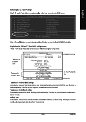
...: Dual BIOS/Q-Flash Select Language Load Fail-Safe Defaults Load Optimized Defaults Set Supervisor Password Set User Password Save & Exit Setup Exit Without Saving F3: Change Language F10: Save & Exit Setup Time, Date, Hard Disk Type... Appendix Exploring the Q-FlashTM / Dual BIOS utility screen The Q-Flash / Dual BIOS utility screen consists of four actions needed to enter BIOS menu. Task menu for Dual BIOS utility: Contains the names of the task. Blocking a task and pressing Enter key on your keyboard to Floppy Enter : Run :Move ESC:Reset F10:Power Off Dual BIOS utility...
...: Dual BIOS/Q-Flash Select Language Load Fail-Safe Defaults Load Optimized Defaults Set Supervisor Password Set User Password Save & Exit Setup Exit Without Saving F3: Change Language F10: Save & Exit Setup Time, Date, Hard Disk Type... Appendix Exploring the Q-FlashTM / Dual BIOS utility screen The Q-Flash / Dual BIOS utility screen consists of four actions needed to enter BIOS menu. Task menu for Dual BIOS utility: Contains the names of the task. Blocking a task and pressing Enter key on your keyboard to Floppy Enter : Run :Move ESC:Reset F10:Power Off Dual BIOS utility...

Manual
Page 77
... the SATA controller on your motherboard during the Windows setup process. When install Windows 2000 or Windows XP from HDDs in the driver CD. First of all chipsets should be recognized during OS installation. English Installing the RAID drivers To install Windows 2000/XP onto a Serial ATA hard disk sucessfully, you need to install required driver for the SATA controller on your motherboard from the motherboard driver CD to a floppy disk. Without the driver, the hard disk may not be listed on the screen...
... the SATA controller on your motherboard during the Windows setup process. When install Windows 2000 or Windows XP from HDDs in the driver CD. First of all chipsets should be recognized during OS installation. English Installing the RAID drivers To install Windows 2000/XP onto a Serial ATA hard disk sucessfully, you need to install required driver for the SATA controller on your motherboard from the motherboard driver CD to a floppy disk. Without the driver, the hard disk may not be listed on the screen...
Manual
Page 79
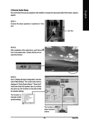
... the audio driver, you use speakers with amplifier to manually modify the speaker settings. STEP 3: Click "C-Media 3D Audio Configuration" and then select "Main Setting". English 2 Channel Audio Setup: We recommend that you 'll find an icon in "Audio System Status". The function to adjust speaker volume. - 79 - The current audio mode is applied. "Smart Jack" would auto-detect the speaker type you connect and gives you the functions to acquire the best sound...
... the audio driver, you use speakers with amplifier to manually modify the speaker settings. STEP 3: Click "C-Media 3D Audio Configuration" and then select "Main Setting". English 2 Channel Audio Setup: We recommend that you 'll find an icon in "Audio System Status". The function to adjust speaker volume. - 79 - The current audio mode is applied. "Smart Jack" would auto-detect the speaker type you connect and gives you the functions to acquire the best sound...
Manual
Page 80
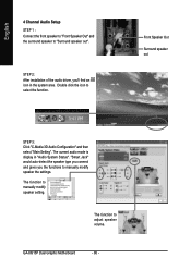
... installation of the audio driver, you the functions to select the function. The function to adjust speaker volume. The function to manually modify speaker setting. English 4 Channel Audio Setup STEP 1 : Connect the front speaker to "Front Speaker Out" and the surround speaker to "Surround speaker out". The current audio mode is display in the system area. GA-8I915P Dual Graphic Motherboard - 80 - Front Speaker Out Surround speaker out STEP 3: Click "C-Media 3D Audio Configuration" and then select "Main Setting...
... installation of the audio driver, you the functions to select the function. The function to adjust speaker volume. The function to manually modify speaker setting. English 4 Channel Audio Setup STEP 1 : Connect the front speaker to "Front Speaker Out" and the surround speaker to "Surround speaker out". The current audio mode is display in the system area. GA-8I915P Dual Graphic Motherboard - 80 - Front Speaker Out Surround speaker out STEP 3: Click "C-Media 3D Audio Configuration" and then select "Main Setting...
Manual
Page 81
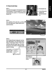
... 3D Audio Configuration" and then select "Main Setting". The current audio mode is display in the system area. STEP 2: After installation of the audio driver, you the functions to manually modify speaker the settings. The function to select the function. English 5.1 Channel Audio Setup STEP 1 : Connect the front speaker to "Front Speaker Out", the surround speaker to "Surround speaker out", and the center/subwoofer speaker to manually modify speaker setting. "Smart Jack" would auto-detect the speaker type you connect...
... 3D Audio Configuration" and then select "Main Setting". The current audio mode is display in the system area. STEP 2: After installation of the audio driver, you the functions to manually modify speaker the settings. The function to select the function. English 5.1 Channel Audio Setup STEP 1 : Connect the front speaker to "Front Speaker Out", the surround speaker to "Surround speaker out", and the center/subwoofer speaker to manually modify speaker setting. "Smart Jack" would auto-detect the speaker type you connect...
Manual
Page 82
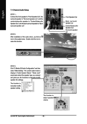
The current audio mode is display in the system area. GA-8I915P Dual Graphic Motherboard - 82 - STEP 2: After installation of the audio driver, you the functions to manually modify speaker the settings. The function to manually modify speaker setting. The function to adjust speaker volume. Front Speaker Out Back surround speaker out Center/Subwoofer Speaker Out Surround speaker out STEP 3: Click "C-Media 3D Audio Configuration" and then select "Main Setting". "Smart Jack" would auto-detect the speaker type you connect and gives...
The current audio mode is display in the system area. GA-8I915P Dual Graphic Motherboard - 82 - STEP 2: After installation of the audio driver, you the functions to manually modify speaker the settings. The function to manually modify speaker setting. The function to adjust speaker volume. Front Speaker Out Back surround speaker out Center/Subwoofer Speaker Out Surround speaker out STEP 3: Click "C-Media 3D Audio Configuration" and then select "Main Setting". "Smart Jack" would auto-detect the speaker type you connect and gives...
Manual
Page 84
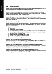
... add an external VGA card? If your board has a Clear CMOS jumper, please refer to the maximum volume? Please refer to enter BIOS and load Fail-Safe Defaults. 7. Question 4: Why does system seem unstable after updating BIOS. Why? Answer: Some advanced options are using is plugged in, so you are hidden in the manual. Connect power cord to MB again and turn on -board battery to leak voltage to disable the onboard VGA. Save changes and reboot...
... add an external VGA card? If your board has a Clear CMOS jumper, please refer to the maximum volume? Please refer to enter BIOS and load Fail-Safe Defaults. 7. Question 4: Why does system seem unstable after updating BIOS. Why? Answer: Some advanced options are using is plugged in, so you are hidden in the manual. Connect power cord to MB again and turn on -board battery to leak voltage to disable the onboard VGA. Save changes and reboot...


