Manual
Page 1
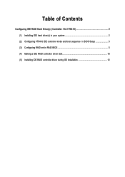
Table of Contents Configuring IDE RAID Hard Drive(s) (Controller: VIA VT6410 2 (1) Installing IDE hard drive(s) in your system 2 (2) Configuring VT6410 IDE controller mode and boot sequence in BIOS Setup 3 (3) Configuring RAID set in RAID BIOS 5 (4) Making a IDE RAID controller driver disk 10 (5) Installing IDE RAID controller driver during OS installation 12
Table of Contents Configuring IDE RAID Hard Drive(s) (Controller: VIA VT6410 2 (1) Installing IDE hard drive(s) in your system 2 (2) Configuring VT6410 IDE controller mode and boot sequence in BIOS Setup 3 (3) Configuring RAID set in RAID BIOS 5 (4) Making a IDE RAID controller driver disk 10 (5) Installing IDE RAID controller driver during OS installation 12
Manual
Page 2
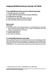
...(s), you have to follow the steps below: ¤å (1) Install IDE hard drive(s) in your computer. (2) Configure VT6410 IDE controller mode and boot sequence in BIOS Setup. (3)* Configure RAID set in your system Attach one hard drive. (b) An empty formatted floppy disk. (c) Windows XP/2000 setup disk. (d) Driver CD for your...
...(s), you have to follow the steps below: ¤å (1) Install IDE hard drive(s) in your computer. (2) Configure VT6410 IDE controller mode and boot sequence in BIOS Setup. (3)* Configure RAID set in your system Attach one hard drive. (b) An empty formatted floppy disk. (c) Windows XP/2000 setup disk. (d) Driver CD for your...

Manual
Page 3
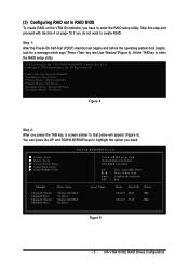
... by default) (Figure 1). Make sure the Onboard H/W RAID item is set this option to enter BIOS Setup during POST (Power-On Self Test). (2) Configuring VT6410 IDE controller mode and boot sequence in BIOS Setup You have to USB Controller USB 2.0 Controller USB Keyboard Support USB Mouse Support Azalia Codec Onboard... Set to SATA Port 0/2 Set to SATA Port 1/3 Set to make sure whether the VT6410 IDE controller are configured correctly in system BIOS Setup and set BIOS boot sequence for the IDE RAID hard drive(s). Step 1: Turn on your computer and press the Del key to Disabled, the VT6410 ...
... by default) (Figure 1). Make sure the Onboard H/W RAID item is set this option to enter BIOS Setup during POST (Power-On Self Test). (2) Configuring VT6410 IDE controller mode and boot sequence in BIOS Setup You have to USB Controller USB 2.0 Controller USB Keyboard Support USB Mouse Support Azalia Codec Onboard... Set to SATA Port 0/2 Set to SATA Port 1/3 Set to make sure whether the VT6410 IDE controller are configured correctly in system BIOS Setup and set BIOS boot sequence for the IDE RAID hard drive(s). Step 1: Turn on your computer and press the Del key to Disabled, the VT6410 ...
Manual
Page 4
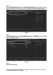
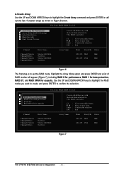
... [Setup] [Enabled] [Enabled] Item Help Menu Level` Select Hard Disk Boot Device Priority KLJI: Move Enter: Select F5: Previous Values Step 4: Save and exit BIOS Setup. +/-/PU/PD: Value F10: Save F6: Fail-Safe Defaults Figure 3 ESC: Exit F1: General Help F7: Optimized Defaults VIA VT6410 IDE RAID Drives Configuration... Limit CPUID Max. KL: Move PU/PD/+/-: Change Priority F10: Save ESC: Exit Figure 2 Step 3: Set First Boot Device under the Advanced BIOS Features menu and then choose the Åé model of the IDE hard drive onto which you want to move it down the list. SCSI...
... [Setup] [Enabled] [Enabled] Item Help Menu Level` Select Hard Disk Boot Device Priority KLJI: Move Enter: Select F5: Previous Values Step 4: Save and exit BIOS Setup. +/-/PU/PD: Value F10: Save F6: Fail-Safe Defaults Figure 3 ESC: Exit F1: General Help F7: Optimized Defaults VIA VT6410 IDE RAID Drives Configuration... Limit CPUID Max. KL: Move PU/PD/+/-: Change Priority F10: Save ESC: Exit Figure 2 Step 3: Set First Boot Device under the Advanced BIOS Features menu and then choose the Åé model of the IDE hard drive onto which you want to move it down the list. SCSI...
Manual
Page 5
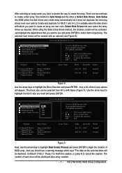
...press the TAB key, a screen similar to enter the RAID setup utility. (3) Configuring RAID set in RAID BIOS To create RAID on page 10 if you need. VIA Technologies, Inc. RAID BIOS Ver 2.11 X Create Array X Delete Array X Create/Delete Spare X Select Boot Array X Serial Number View... 28.63 Hdd ATA133 27.24 Hdd Figure 5 - 5 - VIA VT6410 IDE RAID Drives Configuration Press key into User Window"(Figure 4). VIA VT6410 RAID BIOS Setting Utility V2.11 Copyright (C) VIA Technologies, Inc. Skip this step and proceed with the hard disks attached to VIA RAID controller F1 : K, L ...
...press the TAB key, a screen similar to enter the RAID setup utility. (3) Configuring RAID set in RAID BIOS To create RAID on page 10 if you need. VIA Technologies, Inc. RAID BIOS Ver 2.11 X Create Array X Delete Array X Create/Delete Spare X Select Boot Array X Serial Number View... 28.63 Hdd ATA133 27.24 Hdd Figure 5 - 5 - VIA VT6410 IDE RAID Drives Configuration Press key into User Window"(Figure 4). VIA VT6410 RAID BIOS Setting Utility V2.11 Copyright (C) VIA Technologies, Inc. Skip this step and proceed with the hard disks attached to VIA RAID controller F1 : K, L ...
Manual
Page 6
... Use the UP and DOWN ARROW keys to highlight the RAID mode you want to create and press ENTER to confirm the selection. RAID BIOS Ver 2.11 X Auto Setup For Performance X Array Mode RAID 0 (Striping) X Select Disk Drives X Block Size 64K X Start ... Size(GB) Status ATA 133 28.63 Hdd ATA 133 27.24 Hdd Figure 7 VIA VT6410 IDE RAID Drives Configuration - 6 - RAID BIOS Ver 2.11 X Auto Setup For Data Security X ArRraAyIDM0odfeorRpAeIrDfo0rm(Satnrcipeing) X SeRleActIDis1kfoDrridvaetsa protection X BloRcAkISDiz0e/614K X StaRrAt ICDreSaPtAe NPrfocrecsaspacity Channel Channel0 Master Channel0...
... Use the UP and DOWN ARROW keys to highlight the RAID mode you want to create and press ENTER to confirm the selection. RAID BIOS Ver 2.11 X Auto Setup For Performance X Array Mode RAID 0 (Striping) X Select Disk Drives X Block Size 64K X Start ... Size(GB) Status ATA 133 28.63 Hdd ATA 133 27.24 Hdd Figure 7 VIA VT6410 IDE RAID Drives Configuration - 6 - RAID BIOS Ver 2.11 X Auto Setup For Data Security X ArRraAyIDM0odfeorRpAeIrDfo0rm(Satnrcipeing) X SeRleActIDis1kfoDrridvaetsa protection X BloRcAkISDiz0e/614K X StaRrAt ICDreSaPtAe NPrfocrecsaspacity Channel Channel0 Master Channel0...
Manual
Page 7
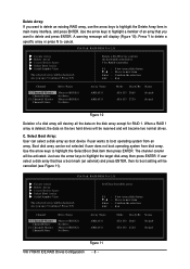
... Drives method, the channel column will be selected from 4K to create the array. After selecting an array mode, you need and press ENTER. RAID BIOS Ver 2.11 X Auto Setup For Performance X Array Mode RAID 0 (Striping) X Select Disk Drives X Block Size 64K X Start Create Process Create ... select the array drives as required. The content of block size options will be destroyed after array creation. - 7 - Auto Setup lets BIOS select the disk drives and create array automatically but it does not duplicate the mirroring drives even user selects Create and duplicate for RAID 1...
... Drives method, the channel column will be selected from 4K to create the array. After selecting an array mode, you need and press ENTER. RAID BIOS Ver 2.11 X Auto Setup For Performance X Array Mode RAID 0 (Striping) X Select Disk Drives X Block Size 64K X Start Create Process Create ... select the array drives as required. The content of block size options will be destroyed after array creation. - 7 - Auto Setup lets BIOS select the disk drives and create array automatically but it does not duplicate the mirroring drives even user selects Create and duplicate for RAID 1...
Manual
Page 8
... 2.11 X Create Array X Delete Array X Create/Delete Spare X Select Boot Array X Serial Number View The selected array will be destoried. VIA Tech. RAID BIOS Ver 2.11 X Create Array X Delete Array X Create/Delete Spare X Select Boot Array X Serial Number View The selected array will be destoried. Select Boot Array: User ...
... 2.11 X Create Array X Delete Array X Create/Delete Spare X Select Boot Array X Serial Number View The selected array will be destoried. VIA Tech. RAID BIOS Ver 2.11 X Create Array X Delete Array X Create/Delete Spare X Select Boot Array X Serial Number View The selected array will be destoried. Select Boot Array: User ...
Manual
Page 9
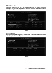
... array status on the screen (Figure 13). VIA Tech. If there are no disk arrays then nothing will be displayed on the lower screen. RAID BIOS Ver 2.11 X Create Array X Delete Array X Create/Delete Spare X Select Boot Array X Serial Number View View the serial number of hard disk, it ... key to next item Confirm the selection Exit Block Size(GB) 64K Size(GB) 54.48 Figure 13 - 9 - VIA VT6410 IDE RAID Drives Configuration RAID BIOS Ver 2.11 Array Mode Stripe Create a RAID array with the hard disks attached to VIA RAID controller F1 : K, L : Enter : ESC : View Array/disk ...
... array status on the screen (Figure 13). VIA Tech. If there are no disk arrays then nothing will be displayed on the lower screen. RAID BIOS Ver 2.11 X Create Array X Delete Array X Create/Delete Spare X Select Boot Array X Serial Number View View the serial number of hard disk, it ... key to next item Confirm the selection Exit Block Size(GB) 64K Size(GB) 54.48 Figure 13 - 9 - VIA VT6410 IDE RAID Drives Configuration RAID BIOS Ver 2.11 Array Mode Stripe Create a RAID array with the hard disks attached to VIA RAID controller F1 : K, L : Enter : ESC : View Array/disk ...
Manual
Page 12
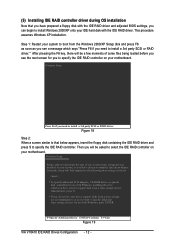
... following mass storage device(s) * To specify additional SCSI adapters, CD-ROM drives, or special disk controllers for use with the IDE RAID driver and adjusted BIOS settings, you can begin to install a 3rd party SCSI or RAID driver." After pressing the F6 key, there will be a few moments of one or...
... following mass storage device(s) * To specify additional SCSI adapters, CD-ROM drives, or special disk controllers for use with the IDE RAID driver and adjusted BIOS settings, you can begin to install a 3rd party SCSI or RAID driver." After pressing the F6 key, there will be a few moments of one or...
Manual
Page 4
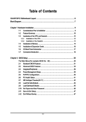
...GA-8I915P-D Motherboard Layout 6 Block Diagram ...7 Chapter 1 Hardware Installation 9 1-1 Considerations Prior to Installation 9 1-2 Feature Summary 10 1-3 Installation of the CPU and Heatsink 12 1-3-1 Installation of the CPU 12 1-3-2 Installation of the Heatsink 13 1-4 Installation of Memory 14 1-5 Installation of Expansion Cards 16 1-6 I/O Back Panel Introduction 17 1-7 Connectors Introduction 18 Chapter 2 BIOS... Setup 29 The Main Menu (For example: BIOS Ver. : E4 30 2-1 Standard CMOS Features 31 2-2 Advanced BIOS Features 34 2-3 ...
...GA-8I915P-D Motherboard Layout 6 Block Diagram ...7 Chapter 1 Hardware Installation 9 1-1 Considerations Prior to Installation 9 1-2 Feature Summary 10 1-3 Installation of the CPU and Heatsink 12 1-3-1 Installation of the CPU 12 1-3-2 Installation of the Heatsink 13 1-4 Installation of Memory 14 1-5 Installation of Expansion Cards 16 1-6 I/O Back Panel Introduction 17 1-7 Connectors Introduction 18 Chapter 2 BIOS... Setup 29 The Main Menu (For example: BIOS Ver. : E4 30 2-1 Standard CMOS Features 31 2-2 Advanced BIOS Features 34 2-3 ...

Manual
Page 5
Chapter 3 Install Drivers 49 3-1 Install Chipset Drivers 49 3-2 SoftwareApplications 50 3-3 Driver CD Information 50 3-4 Hardware Information 51 3-5 Contact Us ...51 Chapter 4 Appendix 53 4-1 Unique Software Utilities 53 4-1-1 EasyTune 5 Introduction 54 4-1-2 Xpress Recovery2 Introduction 55 4-1-3 Flash BIOS Method Introduction 57 4-1-4 2- / 4- / 6- / 8- Channel Audio Function Introduction 66 4-2 Troubleshooting 70 - 5 -
Chapter 3 Install Drivers 49 3-1 Install Chipset Drivers 49 3-2 SoftwareApplications 50 3-3 Driver CD Information 50 3-4 Hardware Information 51 3-5 Contact Us ...51 Chapter 4 Appendix 53 4-1 Unique Software Utilities 53 4-1-1 EasyTune 5 Introduction 54 4-1-2 Xpress Recovery2 Introduction 55 4-1-3 Flash BIOS Method Introduction 57 4-1-4 2- / 4- / 6- / 8- Channel Audio Function Introduction 66 4-2 Troubleshooting 70 - 5 -
Manual
Page 6
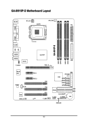
GA-8I915P-D Motherboard Layout KB_MS ATX_12V CPU_FAN LGA775 ATX COMA LPT COMB R_USB GA-8I915P-D LAN USB AUDIO1 AUDIO2 IT8712 F_AUDIO Marvell 8001 CODEC CD_IN BIOS SPDIF_IO Intel 915P IDE1 PCIE_16 DDRII1 DDRII2 DDRII3 DDRII4 PCIE_1 PCIE_2 CI PCI1 PCI2 PCI3 F_USB1 FDD SYS_FAN ICH6 SATA3 SATA2 SATA1 SATA0 VT6410 F_USB2 CLR_CMOS F_PANEL IDE3 IDE2 BAT PWR_LED - 6 -
GA-8I915P-D Motherboard Layout KB_MS ATX_12V CPU_FAN LGA775 ATX COMA LPT COMB R_USB GA-8I915P-D LAN USB AUDIO1 AUDIO2 IT8712 F_AUDIO Marvell 8001 CODEC CD_IN BIOS SPDIF_IO Intel 915P IDE1 PCIE_16 DDRII1 DDRII2 DDRII3 DDRII4 PCIE_1 PCIE_2 CI PCI1 PCI2 PCI3 F_USB1 FDD SYS_FAN ICH6 SATA3 SATA2 SATA1 SATA0 VT6410 F_USB2 CLR_CMOS F_PANEL IDE3 IDE2 BAT PWR_LED - 6 -
Manual
Page 7
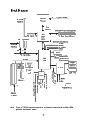
... PCI Bus VT6410 IDE RAID Marvell 8001 RJ45 IDE2/IDE3 Intel ICH6 CODEC 3 PCI Dual Channel Memory MCHCLK (133/200MHz) 66MHz 33MHz 14.318MHz 48MHz BIOS 4 Serial ATA ATA33/66/100 IDE1 Channels Floppy IT 8712 LPT Port COM Ports 8 USB Ports 24MHz 33MHz PS/2 KB/Mouse PCICLK (33MHz) Surround Speaker...-In SPDIF In SPDIF Out (Note) To use a DDRII 600 memory module on the motherboard, you must install an 800MHz FSB processor and overclock in BIOS. - 7 -
... PCI Bus VT6410 IDE RAID Marvell 8001 RJ45 IDE2/IDE3 Intel ICH6 CODEC 3 PCI Dual Channel Memory MCHCLK (133/200MHz) 66MHz 33MHz 14.318MHz 48MHz BIOS 4 Serial ATA ATA33/66/100 IDE1 Channels Floppy IT 8712 LPT Port COM Ports 8 USB Ports 24MHz 33MHz PS/2 KB/Mouse PCICLK (33MHz) Surround Speaker...-In SPDIF In SPDIF Out (Note) To use a DDRII 600 memory module on the motherboard, you must install an 800MHz FSB processor and overclock in BIOS. - 7 -
Manual
Page 10
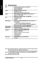
.../XP operating systems Š 4 DDR II DIMM memory slots (supports up to standard PC architecture, a certain amount of 2 IDE devices(IDE1) - GA-8I915P-D Motherboard - 10 - English 1-2 Feature Summary CPU Chipset Memory Slots IDE Connections FDD Connections Onboard SATA Peripherals Onboard LAN Š Supports the latest Intel®... Š Southbridge: Intel® ICH6 Š Supported on the motherboard, you must install an 800MHz FSB processor and overclock in BIOS. (Note 3) Only support ATAPI mode for system usage and therefore the actual memory size is less than the stated amount.
.../XP operating systems Š 4 DDR II DIMM memory slots (supports up to standard PC architecture, a certain amount of 2 IDE devices(IDE1) - GA-8I915P-D Motherboard - 10 - English 1-2 Feature Summary CPU Chipset Memory Slots IDE Connections FDD Connections Onboard SATA Peripherals Onboard LAN Š Supports the latest Intel®... Š Southbridge: Intel® ICH6 Š Supported on the motherboard, you must install an 800MHz FSB processor and overclock in BIOS. (Note 3) Only support ATAPI mode for system usage and therefore the actual memory size is less than the stated amount.

Manual
Page 11
... and error checking messages during boot-up Š Mirroring supports automatic background rebuilds Š Features LBA and Extended Interrupt 13 drive translation in controller onboard BIOS I/O Control Š IT8712 Hardware Monitor Š System voltage detection Š CPU temperature detection Š CPU / System fan speed detection Š CPU warning temperature Š CPU...
... and error checking messages during boot-up Š Mirroring supports automatic background rebuilds Š Features LBA and Extended Interrupt 13 drive translation in controller onboard BIOS I/O Control Š IT8712 Hardware Monitor Š System voltage detection Š CPU temperature detection Š CPU / System fan speed detection Š CPU warning temperature Š CPU...
Manual
Page 12
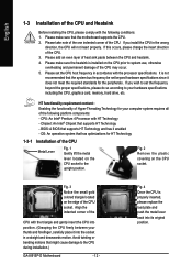
... the following conditions: 1. Fig. 3 Notice the small gold colored triangle located on the CPU prior to the CPU during installation.) GA-8I915P-D Motherboard - 12 - Please take note of the one indented corner of heat sink paste between your hardware specifications including the CPU,...HT Technology 1-3-1 Installation of the CPU with HT Technology - Please set the frequency beyond hardware specifications since it enabled - BIOS: A BIOS that the system bus frequency be set beyond the proper specifications, please do so according to the upright position. Avoid twisting...
... the following conditions: 1. Fig. 3 Notice the small gold colored triangle located on the CPU prior to the CPU during installation.) GA-8I915P-D Motherboard - 12 - Please take note of the one indented corner of heat sink paste between your hardware specifications including the CPU,...HT Technology 1-3-1 Installation of the CPU with HT Technology - Please set the frequency beyond hardware specifications since it enabled - BIOS: A BIOS that the system bus frequency be set beyond the proper specifications, please do so according to the upright position. Avoid twisting...

Manual
Page 14
...only in one direction. Reverse the installation steps when you are designed so that the memory used can be installed in one direction. GA-8I915P-D Motherboard - 14 - Please make sure that the computer power is recommended that memory of Memory Before installing the memory modules, ...Insert the DIMM memory module vertically into the DIMM socket. Then push it down. The motherboard supports DDRII memory modules, whereby BIOS will automatically detect memory capacity and specifications. Fig.2 Close the plastic clip at both edges of the DIMM sockets to prevent hardware damage...
...only in one direction. Reverse the installation steps when you are designed so that the memory used can be installed in one direction. GA-8I915P-D Motherboard - 14 - Please make sure that the computer power is recommended that memory of Memory Before installing the memory modules, ...Insert the DIMM memory module vertically into the DIMM socket. Then push it down. The motherboard supports DDRII memory modules, whereby BIOS will automatically detect memory capacity and specifications. Fig.2 Close the plastic clip at both edges of the DIMM sockets to prevent hardware damage...
Manual
Page 16
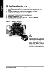
...sure the metal contacts on the card are indeed seated in motherboard. 4. Replace your computer's chassis cover, screws and slot bracket from the computer. 3. GA-8I915P-D Motherboard - 16 - Power on the slot. Remove your computer's chassis cover. 7. Installing a PCI Express x 16 expansion card: Please align the.... 6. Replace the screw to the onboard PCI Express x 16 slot and press firmly down on the computer, if necessary, setup BIOS utility of expansion card from the operating system. English 1-5 Installation of Expansion Cards You can install your VGA card is locked by ...
...sure the metal contacts on the card are indeed seated in motherboard. 4. Replace your computer's chassis cover, screws and slot bracket from the computer. 3. GA-8I915P-D Motherboard - 16 - Power on the slot. Remove your computer's chassis cover. 7. Installing a PCI Express x 16 expansion card: Please align the.... 6. Replace the screw to the onboard PCI Express x 16 slot and press firmly down on the computer, if necessary, setup BIOS utility of expansion card from the operating system. English 1-5 Installation of Expansion Cards You can install your VGA card is locked by ...

Manual
Page 21
... IDE 1 connector. 40 39 2 1 2 40 1 39 7) SATA0/SATA1/SATA2/SATA3 (Serial ATA Connector) Serial ATA can then connect to work properly. Please refer to the BIOS setting for information on settings, please refer to the instructions located on one IDE cable, and the single IDE cable can provide up to150MB/s transfer...
... IDE 1 connector. 40 39 2 1 2 40 1 39 7) SATA0/SATA1/SATA2/SATA3 (Serial ATA Connector) Serial ATA can then connect to work properly. Please refer to the BIOS setting for information on settings, please refer to the instructions located on one IDE cable, and the single IDE cable can provide up to150MB/s transfer...


