Manual
Page 1
Table of Contents Configuring IDE RAID Hard Drive(s) (Controller: VIA VT6410 2 (1) Installing IDE hard drive(s) in your system 2 (2) Configuring VT6410 IDE controller mode and boot sequence in BIOS Setup 3 (3) Configuring RAID set in RAID BIOS 5 (4) Making a IDE RAID controller driver disk 10 (5) Installing IDE RAID controller driver during OS installation 12
Table of Contents Configuring IDE RAID Hard Drive(s) (Controller: VIA VT6410 2 (1) Installing IDE hard drive(s) in your system 2 (2) Configuring VT6410 IDE controller mode and boot sequence in BIOS Setup 3 (3) Configuring RAID set in RAID BIOS 5 (4) Making a IDE RAID controller driver disk 10 (5) Installing IDE RAID controller driver during OS installation 12

Manual
Page 3
... (Power-On Self Test). Step 1: Turn on your computer and press the Del key to Enabled (Enabled by default) (Figure 1). Make sure the Onboard H/W RAID item is set BIOS boot sequence for the IDE RAID hard drive(s). CMOS Setup Utility-Copyright (C) 1984-2004 Award Software Integrated Peripherals On-Chip Primary PCI IDE SATA RAID/AHCI Mode x On-Chip SATA Mode x PATA IDE Set to SATA Port 0/2 Set to SATA Port 1/3 Set to USB Controller USB 2.0 Controller USB Keyboard Support USB Mouse Support Azalia Codec Onboard H/W RAID Onboard H/W 1394 Onboard H/W LAN1 Onboard H/W LAN2 Onboard LAN1 Boot ROM...
... (Power-On Self Test). Step 1: Turn on your computer and press the Del key to Enabled (Enabled by default) (Figure 1). Make sure the Onboard H/W RAID item is set BIOS boot sequence for the IDE RAID hard drive(s). CMOS Setup Utility-Copyright (C) 1984-2004 Award Software Integrated Peripherals On-Chip Primary PCI IDE SATA RAID/AHCI Mode x On-Chip SATA Mode x PATA IDE Set to SATA Port 0/2 Set to SATA Port 1/3 Set to USB Controller USB 2.0 Controller USB Keyboard Support USB Mouse Support Azalia Codec Onboard H/W RAID Onboard H/W 1394 Onboard H/W LAN1 Onboard H/W LAN2 Onboard LAN1 Boot ROM...
Manual
Page 4
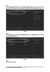
... 3: Set First Boot Device under the Advanced BIOS Features menu and then choose the Åé model of the IDE hard drive onto which you want to install Microsoft Windows 2000/XP (Figure 2). ¤¤ CMOS Setup Utility-Copyright (C) 1984-2004 Award Software Hard Disk Boot Priority ¤å 1. CMOS Setup Utility-Copyright (C) 1984-2004 Award Software Advanced BIOS Features ` Hard Disk Boot Priority First Boot Device Second Boot Device Third Boot Device Password Check CPU Hyper-Threading Limit CPUID Max. Bootable Add-in Cards Item Help Menu Level `` Use...
... 3: Set First Boot Device under the Advanced BIOS Features menu and then choose the Åé model of the IDE hard drive onto which you want to install Microsoft Windows 2000/XP (Figure 2). ¤¤ CMOS Setup Utility-Copyright (C) 1984-2004 Award Software Hard Disk Boot Priority ¤å 1. CMOS Setup Utility-Copyright (C) 1984-2004 Award Software Advanced BIOS Features ` Hard Disk Boot Priority First Boot Device Second Boot Device Third Boot Device Password Check CPU Hyper-Threading Limit CPUID Max. Bootable Add-in Cards Item Help Menu Level `` Use...
Manual
Page 10
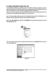
... insert the motherboard driver CD into the CD-ROM drive. Figure 15 VIA VT6410 IDE RAID Drives Configuration - 10 - Quit the installation utility first. The installation utility will appear automatically. First of all, you should see folders and files contained in the driver CD. Ác (4) Making a IDE RAID controller driver disk Åé To install Windows 2000/XP onto a IDE hard disk on the VT6410 controller successfully, you need to install required driver for a file named MENU.exe. Without...
... insert the motherboard driver CD into the CD-ROM drive. Figure 15 VIA VT6410 IDE RAID Drives Configuration - 10 - Quit the installation utility first. The installation utility will appear automatically. First of all, you should see folders and files contained in the driver CD. Ác (4) Making a IDE RAID controller driver disk Åé To install Windows 2000/XP onto a IDE hard disk on the VT6410 controller successfully, you need to install required driver for a file named MENU.exe. Without...
Manual
Page 12
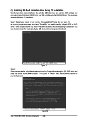
... or more mass storage devices installed in your motherboard. This procedure ¤¤ assumes Windows XP installation. ¤å Step 1: Restart your IDE hard disk with Windows, including those for use with the IDE RAID driver and adjusted BIOS settings, you need to install a 3rd party SCSI or RAID driver. S=Specify Additional Device ENTER=Continue F3=Exit Figure 19 VIA VT6410 IDE RAID Drives Configuration - 12 - Windows Setup Setup could not determine the type of some files being loaded before you...
... or more mass storage devices installed in your motherboard. This procedure ¤¤ assumes Windows XP installation. ¤å Step 1: Restart your IDE hard disk with Windows, including those for use with the IDE RAID driver and adjusted BIOS settings, you need to install a 3rd party SCSI or RAID driver. S=Specify Additional Device ENTER=Continue F3=Exit Figure 19 VIA VT6410 IDE RAID Drives Configuration - 12 - Windows Setup Setup could not determine the type of some files being loaded before you...

Manual
Page 11
...Supports ATAPI mode for HDD Š Supports IDE bus master operation Š Displays status and error checking messages during boot-up Š Mirroring supports automatic background rebuilds Š Features LBA and Extended Interrupt 13 drive translation in controller onboard BIOS I/O Control Š IT8712 Hardware Monitor Š System voltage detection Š CPU temperature detection Š CPU / System fan speed detection Š CPU warning temperature Š CPU / System fan failure warning Š CPU smart fan control BIOS Š Use of licensed AWARD BIOS Š Supports...
...Supports ATAPI mode for HDD Š Supports IDE bus master operation Š Displays status and error checking messages during boot-up Š Mirroring supports automatic background rebuilds Š Features LBA and Extended Interrupt 13 drive translation in controller onboard BIOS I/O Control Š IT8712 Hardware Monitor Š System voltage detection Š CPU temperature detection Š CPU / System fan speed detection Š CPU warning temperature Š CPU / System fan failure warning Š CPU smart fan control BIOS Š Use of licensed AWARD BIOS Š Supports...
Manual
Page 15
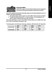
... used if one or three DDR II memory modules are installed. 2. Hardware Installation To enable Dual Channel mode with 2 or 4 memory modules, it is for Dual Channel Technology to use memory modules of identical brand, size, chips, and speed. The following explanations due to the limitation of Memory Bus will double. If you want to operate the Dual Channel Technology, please note the following table is recommended to work. English Dual Channel DDR II GA-8I915P-D supports the Dual Channel Technology...
... used if one or three DDR II memory modules are installed. 2. Hardware Installation To enable Dual Channel mode with 2 or 4 memory modules, it is for Dual Channel Technology to use memory modules of identical brand, size, chips, and speed. The following explanations due to the limitation of Memory Bus will double. If you want to operate the Dual Channel Technology, please note the following table is recommended to work. English Dual Channel DDR II GA-8I915P-D supports the Dual Channel Technology...

Manual
Page 21
... settings, please refer to the instructions located on one IDE cable, and the single IDE cable can then connect to the IDE 1 connector. 40 39 2 1 2 40 1 39 7) SATA0/SATA1/SATA2/SATA3 (Serial ATA Connector) Serial ATA can connect to one IDE device as Master and the other as Slave (for the Serial ATA and install the proper driver in order to work properly, please attach it to two IDE devices (hard drive or optical drive...
... settings, please refer to the instructions located on one IDE cable, and the single IDE cable can then connect to the IDE 1 connector. 40 39 2 1 2 40 1 39 7) SATA0/SATA1/SATA2/SATA3 (Serial ATA Connector) Serial ATA can connect to one IDE device as Master and the other as Slave (for the Serial ATA and install the proper driver in order to work properly, please attach it to two IDE devices (hard drive or optical drive...
Manual
Page 22
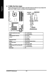
...IDE Hard Disk Active LED HD (IDE Hard Disk Active LED) (Blue) SPEAK (Speaker Connector) (Amber) RES (Reset Switch) (Green) PW (Power Switch) (Red) MSG(Message LED/Power/Sleep LED) (Yellow) NC( Purple) Pin 1: LED anode(+) Pin 2: LED cathode(-) Pin 1: Power Pin 2- Pin 3: NC Pin 4: Data(-) Open: Normal Close: Reset Hardware System Open: Normal Close: Power On/Off Pin 1: LED anode(+) Pin 2: LED cathode(-) NC GA-8I915P-D Motherboard - 22 - Message LED/ Power/ Sleep LED Speaker Connector Power Switch MSG+ MSG- English 8) F_PANEL (Front Panel Jumper) Please connect the power LED, PC speaker...
...IDE Hard Disk Active LED HD (IDE Hard Disk Active LED) (Blue) SPEAK (Speaker Connector) (Amber) RES (Reset Switch) (Green) PW (Power Switch) (Red) MSG(Message LED/Power/Sleep LED) (Yellow) NC( Purple) Pin 1: LED anode(+) Pin 2: LED cathode(-) Pin 1: Power Pin 2- Pin 3: NC Pin 4: Data(-) Open: Normal Close: Reset Hardware System Open: Normal Close: Power On/Off Pin 1: LED anode(+) Pin 2: LED cathode(-) NC GA-8I915P-D Motherboard - 22 - Message LED/ Power/ Sleep LED Speaker Connector Power Switch MSG+ MSG- English 8) F_PANEL (Front Panel Jumper) Please connect the power LED, PC speaker...

Manual
Page 25
... optional front USB cable, please contact your system to work or even damage it. The "USB Device Wake up From S3" is only supported by rear USB ports. 2 10 1 9 Pin No. 1 2 3 4 5 6 7 8 9 10 Definition Power Power USB DXUSB DyUSB DX+ USB Dy+ GND GND No Pin NC 14) CI (Chassis Intrusion, Case Open) This 2-pin connector allows your local dealer. Pin No. Hardware Installation Check the pin assignment carefully while you connect the front USB cable, incorrect connection...
... optional front USB cable, please contact your system to work or even damage it. The "USB Device Wake up From S3" is only supported by rear USB ports. 2 10 1 9 Pin No. 1 2 3 4 5 6 7 8 9 10 Definition Power Power USB DXUSB DyUSB DX+ USB Dy+ GND GND No Pin NC 14) CI (Chassis Intrusion, Case Open) This 2-pin connector allows your local dealer. Pin No. Hardware Installation Check the pin assignment carefully while you connect the front USB cable, incorrect connection...
Manual
Page 30
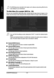
... Load Optimized Defaults in the BIOS when somehow the system works not stable as figure below) will appear on the screen. GA-8I915P-D Motherboard - 30 - If you can't find the setting you enter Award BIOS CMOS Setup Utility, the Main Menu (as usual. Use arrow keys to select among the items and press to search the advanced option hidden. This action makes the system reset to the default for stability. „ Standard CMOS...
... Load Optimized Defaults in the BIOS when somehow the system works not stable as figure below) will appear on the screen. GA-8I915P-D Motherboard - 30 - If you can't find the setting you enter Award BIOS CMOS Setup Utility, the Main Menu (as usual. Use arrow keys to select among the items and press to search the advanced option hidden. This action makes the system reset to the default for stability. „ Standard CMOS...

Manual
Page 32
... zone Sector Number of sectors Drive A / Drive B The category identifies the types of currently installed hard disk. None 360K, 5.25" No floppy drive installed 5.25 inch PC-type standard drive; 360K byte capacity. 1.2M, 5.25" 5.25 inch AT-type high-density drive; 1.2M byte capacity (3.5 inch when 3 Mode is 3 mode Floppy Drive. You can manually input the correct settings Access Mode Use this if no SATA IDE devices are 3 mode Floppy Drives. Enter the appropriate option based on the outside drive casing. GA-8I915P-D Motherboard - 32 - IDE Device Setup.
... zone Sector Number of sectors Drive A / Drive B The category identifies the types of currently installed hard disk. None 360K, 5.25" No floppy drive installed 5.25 inch PC-type standard drive; 360K byte capacity. 1.2M, 5.25" 5.25 inch AT-type high-density drive; 1.2M byte capacity (3.5 inch when 3 Mode is 3 mode Floppy Drive. You can manually input the correct settings Access Mode Use this if no SATA IDE devices are 3 mode Floppy Drives. Enter the appropriate option based on the outside drive casing. GA-8I915P-D Motherboard - 32 - IDE Device Setup.

Manual
Page 42
...Control Disabled Disable this function is enabled, CPU fan will automatically assign by CPU detection. CPU Clock Ratio This setup option will run at different speed depending on their requirements. (Default Value) CPU Smart FAN Mode This option is available only when CPU Smart FAN Control is not changeable. Note: In fact, the Voltage option can adjust the fan speed with a 4-pin fan power cable. GA-8I915P-D Motherboard - 42 - For power end-user use a CPU fan with Easy Tune based on CPU temperature. Auto BIOS autodetects the type of CPU fan you installed and sets...
...Control Disabled Disable this function is enabled, CPU fan will automatically assign by CPU detection. CPU Clock Ratio This setup option will run at different speed depending on their requirements. (Default Value) CPU Smart FAN Mode This option is available only when CPU Smart FAN Control is not changeable. Note: In fact, the Voltage option can adjust the fan speed with a 4-pin fan power cable. GA-8I915P-D Motherboard - 42 - For power end-user use a CPU fan with Easy Tune based on CPU temperature. Auto BIOS autodetects the type of CPU fan you installed and sets...
Manual
Page 46
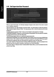
... to access only basic items. If you select "System" at "Password Check" in Advance BIOS Features Menu, you will appear to confirm the password being disabled. Type the password again and press . English 2-10 Set Supervisor/User Password CMOS Setup Utility-Copyright (C) 1984-2005 Award Software ` Standard CMOS Features ` Advanced BIOS Features ` Integrated Peripherals ` Power Management Setup ` PnP/PCI ConfigurationEsnter Password: ` PC Health Status ` MB Intelligent Tweaker(M.I.T.) Load Fail-Safe Defaults Load Optimized Defaults Set Supervisor Password Set User Password Save...
... to access only basic items. If you select "System" at "Password Check" in Advance BIOS Features Menu, you will appear to confirm the password being disabled. Type the password again and press . English 2-10 Set Supervisor/User Password CMOS Setup Utility-Copyright (C) 1984-2005 Award Software ` Standard CMOS Features ` Advanced BIOS Features ` Integrated Peripherals ` Power Management Setup ` PnP/PCI ConfigurationEsnter Password: ` PC Health Status ` MB Intelligent Tweaker(M.I.T.) Load Fail-Safe Defaults Load Optimized Defaults Set Supervisor Password Set User Password Save...
Manual
Page 49
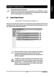
... came with your motherboard into your CD-ROM drive, the driver CD-title will restart your system the "Xpress Install" will show the installation guide. Some device drivers will auto start and show a question mark "?" After restarting your system automatically. in Windows XP. or you can install others application. For USB2.0 driver support under "Device Manager". Install Drivers After install Windows Service Pack, it will continue to install other drivers. Please pick the...
... came with your motherboard into your CD-ROM drive, the driver CD-title will restart your system the "Xpress Install" will show the installation guide. Some device drivers will auto start and show a question mark "?" After restarting your system automatically. in Windows XP. or you can install others application. For USB2.0 driver support under "Device Manager". Install Drivers After install Windows Service Pack, it will continue to install other drivers. Please pick the...
Manual
Page 53
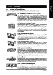
... settings into different modes within BIOS setup in order to open up errors resulting from a recommended memory module list. C.O.M. (Corporate Online Management) A web-based system management tool that eliminates system boot-up the PC chassis and short-circuit the "Clear CMOS" pins or the battery on the U-Plus D.P.S. English Chapter 4 Appendix 4-1 Unique Software Utilities (Not all model support these Unique Software Utilities, please check your MB features.) U-PLUS D.P.S. (Universal Plus Dual Power...
... settings into different modes within BIOS setup in order to open up errors resulting from a recommended memory module list. C.O.M. (Corporate Online Management) A web-based system management tool that eliminates system boot-up the PC chassis and short-circuit the "Clear CMOS" pins or the battery on the U-Plus D.P.S. English Chapter 4 Appendix 4-1 Unique Software Utilities (Not all model support these Unique Software Utilities, please check your MB features.) U-PLUS D.P.S. (Universal Plus Dual Power...
Manual
Page 55
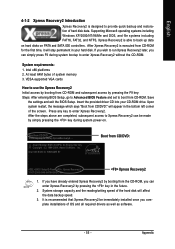
... speed of OS and all required drivers as well as software. - 55 - English 4-1-2 Xpress Recovery2 Introduction Xpress Recovery2 is designed to enter Xpress Recovery2. Intel 945 BIOS for the first time, it will affect the data backup speed. 3. VESA-supported VGA cards How to use the Xpress Recovery2 Initial access by booting from CD-ROM and subsequent access by pressing the key in your CD-ROM drive...
... speed of OS and all required drivers as well as software. - 55 - English 4-1-2 Xpress Recovery2 Introduction Xpress Recovery2 is designed to enter Xpress Recovery2. Intel 945 BIOS for the first time, it will affect the data backup speed. 3. VESA-supported VGA cards How to use the Xpress Recovery2 Initial access by booting from CD-ROM and subsequent access by pressing the key in your CD-ROM drive...
Manual
Page 58
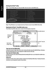
... Disable Boot From Main Bios Auto Recovery Enable Halt On Error Disable Copy Main ROM Data to Backup Load Default Settings Save Settings to CMOS Q-Flash Utility Load Main BIOS from Floppy Load Backup BIOS from Floppy Save Main BIOS to Floppy Save Backup BIOS to perform these actions. Task menu for Dual BIOS utility: Contains the names of four tasks. GA-8I915P-D Motherboard - 58 - Step 2: Press F8 button on your keyboard to enter the Dual BIOS/Q-Flash utility. Blocking a task and pressing Enter key on your keyboards to Floppy Enter : Run :Move ESC:Reset F10:Power Off Dual BIOS...
... Disable Boot From Main Bios Auto Recovery Enable Halt On Error Disable Copy Main ROM Data to Backup Load Default Settings Save Settings to CMOS Q-Flash Utility Load Main BIOS from Floppy Load Backup BIOS from Floppy Save Main BIOS to Floppy Save Backup BIOS to perform these actions. Task menu for Dual BIOS utility: Contains the names of four tasks. GA-8I915P-D Motherboard - 58 - Step 2: Press F8 button on your keyboard to enter the Dual BIOS/Q-Flash utility. Blocking a task and pressing Enter key on your keyboards to Floppy Enter : Run :Move ESC:Reset F10:Power Off Dual BIOS...

Manual
Page 64
... BIOS unzip file, downloading from internet or any other methods (such as: 8I915P-D.E4). Complete update process following the instruction. Update BIOS through Internet: a. English Method 2 : @BIOSTM Utility If you do not have a DOS startup disk, we recommend that you use the new @BIOS utility. @BIOS allows users to download the latest version of BIOS. Do not click "Internet Update" icon b. Select the exact model name on your motherboard e. Fig 1. The @BIOS Utility...
... BIOS unzip file, downloading from internet or any other methods (such as: 8I915P-D.E4). Complete update process following the instruction. Update BIOS through Internet: a. English Method 2 : @BIOSTM Utility If you do not have a DOS startup disk, we recommend that you use the new @BIOS utility. @BIOS allows users to download the latest version of BIOS. Do not click "Internet Update" icon b. Select the exact model name on your motherboard e. Fig 1. The @BIOS Utility...
Manual
Page 70
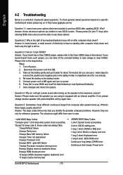
... failure 7 beeps Processor exception interrupt error 8 beeps Display memory read/write failure 9 beeps ROM checksum error 10 beeps CMOS shutdown register read/write error 11 beeps Cache memory bad AWARD BIOS Beep Codes 1 short: System boots successfully 2 short: CMOS setting error 1 long 1 short: DRAM or M/B error 1 long 2 short: Monitor or display card error 1 long 3 short: Keyboard error 1 long 9 short: BIOS ROM error Continuous long beeps: DRAM error Continuous short beeps: Power error GA-8I915P-D Motherboard - 70 - Turn off the on-board battery to leak voltage to clear CMOS. To...
... failure 7 beeps Processor exception interrupt error 8 beeps Display memory read/write failure 9 beeps ROM checksum error 10 beeps CMOS shutdown register read/write error 11 beeps Cache memory bad AWARD BIOS Beep Codes 1 short: System boots successfully 2 short: CMOS setting error 1 long 1 short: DRAM or M/B error 1 long 2 short: Monitor or display card error 1 long 3 short: Keyboard error 1 long 9 short: BIOS ROM error Continuous long beeps: DRAM error Continuous short beeps: Power error GA-8I915P-D Motherboard - 70 - Turn off the on-board battery to leak voltage to clear CMOS. To...


