Manual
Page 5
Table of Contents GA-8I915MD-G / GA-8I915MD-GV Motherboard Layout 7 Block Diagram (GA-8I915MD-G 8 Block Diagram (GA-8I915MD-GV 9 Chapter 1 Hardware Installation 11 1-1 Considerations Prior to Installation 11 1-2 Feature Summary 12 1-3 ...BIOS Features 36 2-3 IntegratedPeripherals 38 2-4 Power Management Setup 40 2-5 PnP/PCI Configurations 41 2-6 PC Health Status 42 2-7 Frequency/Voltage Control 44 2-8 Load Fail-Safe Defaults 45 2-9 Load Optimized Defaults 45 2-10 Set Supervisor/User Password 46 2-11 Save & Exit Setup 47 2-12 Exit Without Saving 47 "*" Only for GA-8I915MD-GV...
Table of Contents GA-8I915MD-G / GA-8I915MD-GV Motherboard Layout 7 Block Diagram (GA-8I915MD-G 8 Block Diagram (GA-8I915MD-GV 9 Chapter 1 Hardware Installation 11 1-1 Considerations Prior to Installation 11 1-2 Feature Summary 12 1-3 ...BIOS Features 36 2-3 IntegratedPeripherals 38 2-4 Power Management Setup 40 2-5 PnP/PCI Configurations 41 2-6 PC Health Status 42 2-7 Frequency/Voltage Control 44 2-8 Load Fail-Safe Defaults 45 2-9 Load Optimized Defaults 45 2-10 Set Supervisor/User Password 46 2-11 Save & Exit Setup 47 2-12 Exit Without Saving 47 "*" Only for GA-8I915MD-GV...
Manual
Page 6
Chapter 3 Drivers Installation 49 3-1 Install Chipset Drivers 49 3-2 SoftwareApplications 50 3-3 Driver CD Information 50 3-4 Hardware Information 51 3-5 Contact Us ...51 Chapter 4 Appendix 53 4-1 Unique Software Utilities 53 4-1-1 EasyTune 5 Introduction 54 4-1-2 Xpress Recovery2 Introduction 55 4-1-3 Flash BIOS Method Introduction 57 4-1-4 2 / 4 / 6 Channel Audio Function Introduction 66 4-2 Troubleshooting 72 - 6 -
Chapter 3 Drivers Installation 49 3-1 Install Chipset Drivers 49 3-2 SoftwareApplications 50 3-3 Driver CD Information 50 3-4 Hardware Information 51 3-5 Contact Us ...51 Chapter 4 Appendix 53 4-1 Unique Software Utilities 53 4-1-1 EasyTune 5 Introduction 54 4-1-2 Xpress Recovery2 Introduction 55 4-1-3 Flash BIOS Method Introduction 57 4-1-4 2 / 4 / 6 Channel Audio Function Introduction 66 4-2 Troubleshooting 72 - 6 -
Manual
Page 7
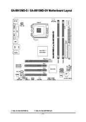
Only for GA-8I915MD-G. GA-8I915MD-G / GA-8I915MD-GV Motherboard Layout KB_MS ATX_12V LGA775 CPU_FAN ATX CI IDE1 IT8712 COMA GA-8I915MD-G or GA-8I915MD-GV LPT LAN VGA USB DDRII2 PWR_LED F_PANEL USB AUDIO Intel 915G / Intel 915GV PCIE_16 RTL8110S / RTL8100C CD_IN CODEC AUX_IN F_AUDIO SUR_CEN SPDIF_IO COMB PCI1 PCI2 Intel ICH6 PCI3 SYS_FAN F_USB1 F_USB2 DDRII1 FDD SATA1 SATA0 BIOS BAT CLR_CMOS Only for GA-8I915MD-GV. - 7 -
Only for GA-8I915MD-G. GA-8I915MD-G / GA-8I915MD-GV Motherboard Layout KB_MS ATX_12V LGA775 CPU_FAN ATX CI IDE1 IT8712 COMA GA-8I915MD-G or GA-8I915MD-GV LPT LAN VGA USB DDRII2 PWR_LED F_PANEL USB AUDIO Intel 915G / Intel 915GV PCIE_16 RTL8110S / RTL8100C CD_IN CODEC AUX_IN F_AUDIO SUR_CEN SPDIF_IO COMB PCI1 PCI2 Intel ICH6 PCI3 SYS_FAN F_USB1 F_USB2 DDRII1 FDD SATA1 SATA0 BIOS BAT CLR_CMOS Only for GA-8I915MD-GV. - 7 -
Manual
Page 8
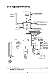
Block Diagram (GA-8I915MD-G) PCI-ECLK (100MHz) LGA775 Processor CPUCLK+/-(200/133MHz) PCI Express x16 VGA PCI Bus RTL8110S RJ45 Host Interface DDRII 600(Note)/533/400MHz DIMM Intel 915G MCH Dual Channel Memory MCHCLK (200/133MHz) 66MHz 33MHz 14.318MHz 48MHz BIOS 2 Serial ATA Intel ATA33/66/100 ICH6 IDE1 Channel Floppy IT8712 LPT Port COM Ports 3 PCI CODEC 8 USB Ports 24MHz 33MHz PS/2 KB/Mouse MIC Line-Out Line-In PCICLK (33MHz) (Note) To use a DDRII 600 memory module on the motherboard, you must install an 800MHz FSB processor and overclock in BIOS. - 8 -
Block Diagram (GA-8I915MD-G) PCI-ECLK (100MHz) LGA775 Processor CPUCLK+/-(200/133MHz) PCI Express x16 VGA PCI Bus RTL8110S RJ45 Host Interface DDRII 600(Note)/533/400MHz DIMM Intel 915G MCH Dual Channel Memory MCHCLK (200/133MHz) 66MHz 33MHz 14.318MHz 48MHz BIOS 2 Serial ATA Intel ATA33/66/100 ICH6 IDE1 Channel Floppy IT8712 LPT Port COM Ports 3 PCI CODEC 8 USB Ports 24MHz 33MHz PS/2 KB/Mouse MIC Line-Out Line-In PCICLK (33MHz) (Note) To use a DDRII 600 memory module on the motherboard, you must install an 800MHz FSB processor and overclock in BIOS. - 8 -
Manual
Page 9
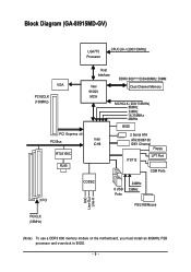
Block Diagram (GA-8I915MD-GV) LGA775 Processor CPUCLK+/-(200/133MHz) VGA PCI-ECLK (100MHz) PCI Express x4 PCI Bus RTL8100C RJ45 Host Interface Intel 915GV MCH DDRII 600(Note)533/400MHz DIMM Dual Channel Memory MCHCLK (200/133MHz) 66MHz 33MHz 14.318MHz 48MHz BIOS 2 Serial ATA Intel ATA33/66/100 ICH6 IDE1 Channel Floppy IT8712 LPT Port COM Ports 3 PCI CODEC 8 USB Ports 24MHz 33MHz PS/2 KB/Mouse MIC Line-Out Line-In PCICLK (33MHz) (Note) To use a DDRII 600 memory module on the motherboard, you must install an 800MHz FSB processor and overclock in BIOS. - 9 -
Block Diagram (GA-8I915MD-GV) LGA775 Processor CPUCLK+/-(200/133MHz) VGA PCI-ECLK (100MHz) PCI Express x4 PCI Bus RTL8100C RJ45 Host Interface Intel 915GV MCH DDRII 600(Note)533/400MHz DIMM Dual Channel Memory MCHCLK (200/133MHz) 66MHz 33MHz 14.318MHz 48MHz BIOS 2 Serial ATA Intel ATA33/66/100 ICH6 IDE1 Channel Floppy IT8712 LPT Port COM Ports 3 PCI CODEC 8 USB Ports 24MHz 33MHz PS/2 KB/Mouse MIC Line-Out Line-In PCICLK (33MHz) (Note) To use a DDRII 600 memory module on the motherboard, you must install an 800MHz FSB processor and overclock in BIOS. - 9 -
Manual
Page 12
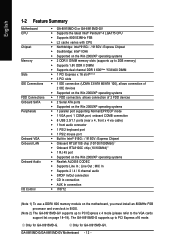
... (rear x 4, front x 4 via cable) Š 1 front audio connector Š 1 PS/2 keyboard port Š 1 PS/2 mouse port Š Built-in BIOS. (Note 2) The GA-8I915MD-GV supports up to PCI Express x 4 mode (please refer to the VGA cards support list on page 18~19). Line Out ; Only for...Feature Summary Motherboard CPU Chipset Memory Slots IDE Connections FDD Connections Onboard SATA Peripherals Onboard VGA Onboard LAN Onboard Audio I/O Control Š GA-8I915MD-G or GA-8I915MD-GV Š Supports the latest Intel® Pentium® 4 LGA775 CPU Š Supports 800/533MHz FSB Š L2 cache ...
... (rear x 4, front x 4 via cable) Š 1 front audio connector Š 1 PS/2 keyboard port Š 1 PS/2 mouse port Š Built-in BIOS. (Note 2) The GA-8I915MD-GV supports up to PCI Express x 4 mode (please refer to the VGA cards support list on page 18~19). Line Out ; Only for...Feature Summary Motherboard CPU Chipset Memory Slots IDE Connections FDD Connections Onboard SATA Peripherals Onboard VGA Onboard LAN Onboard Audio I/O Control Š GA-8I915MD-G or GA-8I915MD-GV Š Supports the latest Intel® Pentium® 4 LGA775 CPU Š Supports 800/533MHz FSB Š L2 cache ...
Manual
Page 13
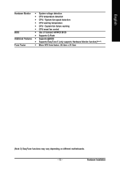
Hardware Installation English Hardware Monitor Š System voltage detection Š CPU temperature detection Š CPU / System fan speed detection Š CPU warning temperature Š CPU / System fan failure warning Š CPU smart fan control BIOS Š Use of licensed AWARD BIOS Š Supports Q-Flash Additional Features Š Supports @BIOS Š Supports EasyTune 5 (only supports Hardware Monitor function)(Note 3) Form Factor Š Micro ATX form factor; 24.4cm x 21.5cm (Note 3) EasyTune functions may vary depending on different motherboards. - 13 -
Hardware Installation English Hardware Monitor Š System voltage detection Š CPU temperature detection Š CPU / System fan speed detection Š CPU warning temperature Š CPU / System fan failure warning Š CPU smart fan control BIOS Š Use of licensed AWARD BIOS Š Supports Q-Flash Additional Features Š Supports @BIOS Š Supports EasyTune 5 (only supports Hardware Monitor function)(Note 3) Form Factor Š Micro ATX form factor; 24.4cm x 21.5cm (Note 3) EasyTune functions may vary depending on different motherboards. - 13 -
Manual
Page 14
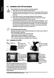
... located on the edge of the CPU socket. If you install the CPU in the wrong direction, the CPU will not insert properly. BIOS: A BIOS that might cause damage to system use, otherwise overheating and permanent damage of the CPU may occur. 5. OS: An operation system that... HT Technology and has it into its original position. Fig. 2 Remove the plastic covering on the CPU prior to the CPU during installation.) GA-8I915MD-G/GA-8I915MD-GV Motherboard - 14 - Align the indented corner of the CPU with the processor specifications. Fig. 4 Once the CPU is not recommended that has...
... located on the edge of the CPU socket. If you install the CPU in the wrong direction, the CPU will not insert properly. BIOS: A BIOS that might cause damage to system use, otherwise overheating and permanent damage of the CPU may occur. 5. OS: An operation system that... HT Technology and has it into its original position. Fig. 2 Remove the plastic covering on the CPU prior to the CPU during installation.) GA-8I915MD-G/GA-8I915MD-GV Motherboard - 14 - Align the indented corner of the CPU with the processor specifications. Fig. 4 Once the CPU is not recommended that has...
Manual
Page 16
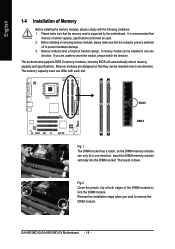
...module can be installed in only one direction. Insert the DIMM memory module vertically into the DIMM socket. Then push it down. GA-8I915MD-G/GA-8I915MD-GV Motherboard - 16 - Please make sure that the memory used is recommended that they can be used can only fit in one direction...that memory of similar capacity, specifications and brand be inserted only in one direction. The motherboard supports DDR II memory modules, whereby BIOS will automatically detect memory capacity and specifications. It is supported by the motherboard. Notch DDR II Fig.1 The DIMM socket has ...
...module can be installed in only one direction. Insert the DIMM memory module vertically into the DIMM socket. Then push it down. GA-8I915MD-G/GA-8I915MD-GV Motherboard - 16 - Please make sure that the memory used is recommended that they can be used can only fit in one direction...that memory of similar capacity, specifications and brand be inserted only in one direction. The motherboard supports DDR II memory modules, whereby BIOS will automatically detect memory capacity and specifications. It is supported by the motherboard. Notch DDR II Fig.1 The DIMM socket has ...
Manual
Page 18
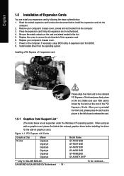
... GA-8I915MD-G/GA-8I915MD-GV Motherboard - 18 - Power on the slot. Installing a PCI Express x 16 expansion card: Please align the VGA card to the onboard PCI Express x 16 slot and press firmly down on the computer, if necessary, setup BIOS utility of expansion card from BIOS... related driver from the computer. 3. PCI Express x16 Cards Graphics Chip Nvidia Maker Gigabyte Gigabyte Gigabyte Gigabyte Gigabyte Gigabyte Model Name GV-NX53128D GV-NX57128D GV-NX59128D GV-NX62128D GV-NX66256D GV-NX66T128VP "*" Only for the add-on graphics card, please first delete the onboard graphics...
... GA-8I915MD-G/GA-8I915MD-GV Motherboard - 18 - Power on the slot. Installing a PCI Express x 16 expansion card: Please align the VGA card to the onboard PCI Express x 16 slot and press firmly down on the computer, if necessary, setup BIOS utility of expansion card from BIOS... related driver from the computer. 3. PCI Express x16 Cards Graphics Chip Nvidia Maker Gigabyte Gigabyte Gigabyte Gigabyte Gigabyte Gigabyte Model Name GV-NX53128D GV-NX57128D GV-NX59128D GV-NX62128D GV-NX66256D GV-NX66T128VP "*" Only for the add-on graphics card, please first delete the onboard graphics...
Manual
Page 24
... 1 GND 2 TXP 3 TXN 4 GND 1 7 5 RXN 6 RXP 7 GND GA-8I915MD-G/GA-8I915MD-GV Motherboard - 24 - If you wish to connect two IDE devices, please set the jumper on the IDE device). 40 39 2 1 7) SATA0/SATA1 (SATA Connector) SATA can then connect to 150MB/s transfer rate. Please refer to the BIOS setting for information on settings, please refer...
... 1 GND 2 TXP 3 TXN 4 GND 1 7 5 RXN 6 RXP 7 GND GA-8I915MD-G/GA-8I915MD-GV Motherboard - 24 - If you wish to connect two IDE devices, please set the jumper on the IDE device). 40 39 2 1 7) SATA0/SATA1 (SATA Connector) SATA can then connect to 150MB/s transfer rate. Please refer to the BIOS setting for information on settings, please refer...

Manual
Page 29
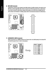
Please contact your nearest dealer for optional COMB cable. 2 10 1 9 Pin No. 1 2 3 4 5 6 7 8 9 10 Definition NDCDBNSINB NSOUTB NDTRBGND NDSRBNRTSBNCTSBNRIBNo Pin 17) CI (Chassis Intrusion, Case Open) This 2-pin connector allows your system to detect if the chassis cover is removed. Definition 1 1 Signal 2 GND - 29 - You can check the "Case Opened" status in BIOS Setup. Pin No. English 16) COMB (COMB Connector) Be careful with the polarity of the COMB connector. Hardware Installation Check the pin assignments while you connect the COMB cable.
Please contact your nearest dealer for optional COMB cable. 2 10 1 9 Pin No. 1 2 3 4 5 6 7 8 9 10 Definition NDCDBNSINB NSOUTB NDTRBGND NDSRBNRTSBNCTSBNRIBNo Pin 17) CI (Chassis Intrusion, Case Open) This 2-pin connector allows your system to detect if the chassis cover is removed. Definition 1 1 Signal 2 GND - 29 - You can check the "Case Opened" status in BIOS Setup. Pin No. English 16) COMB (COMB Connector) Be careful with the polarity of the COMB connector. Hardware Installation Check the pin assignments while you connect the COMB cable.
Manual
Page 31
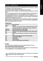
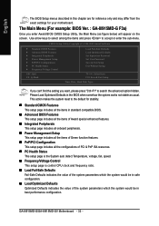
...power to a new BIOS, either GIGABYTE's Q-Flash or @BIOS utility can enter the BIOS setup screen by pressing "Ctrl + F1". If you wish to upgrade to the CMOS SRAM. Exit current page and return to DOS before upgrading BIOS but directly download and update BIOS from BIOS default table Load the ... changes Decrease the numeric value or make changes General help window that may result in system malfunction. - 31 - English Chapter 2 BIOS Setup BIOS (Basic Input and Output System) includes a CMOS SETUP utility which allows user to configure required settings or to use and the possible...
...power to a new BIOS, either GIGABYTE's Q-Flash or @BIOS utility can enter the BIOS setup screen by pressing "Ctrl + F1". If you wish to upgrade to the CMOS SRAM. Exit current page and return to DOS before upgrading BIOS but directly download and update BIOS from BIOS default table Load the ... changes Decrease the numeric value or make changes General help window that may result in system malfunction. - 31 - English Chapter 2 BIOS Setup BIOS (Basic Input and Output System) includes a CMOS SETUP utility which allows user to configure required settings or to use and the possible...
Manual
Page 32
... best performance configuration. English The BIOS Setup menus described in the BIOS when somehow the system works not stable as figure below) will appear on the screen. This action makes the system reset to accept or enter the sub-menu. GA-8I915MD-G/GA-8I915MD-GV Motherboard - 32 - If you... can't find the setting you enter Award BIOS CMOS Setup Utility, the Main Menu (as usual. CMOS Setup Utility-Copyright (C) 1984-2005 Award ...
... best performance configuration. English The BIOS Setup menus described in the BIOS when somehow the system works not stable as figure below) will appear on the screen. This action makes the system reset to accept or enter the sub-menu. GA-8I915MD-G/GA-8I915MD-GV Motherboard - 32 - If you... can't find the setting you enter Award BIOS CMOS Setup Utility, the Main Menu (as usual. CMOS Setup Utility-Copyright (C) 1984-2005 Award ...

Manual
Page 33
It allows you to limit access to the system and Setup, or just to CMOS and exit setup. „ Exit Without Saving Abandon all CMOS value changes and exit setup. - 33 - It allows you to limit access to the system. „ Save & Exit Setup Save CMOS value settings to Setup. „ Set User Password Change, set , or disable password. BIOS Setup English „ Set Supervisor Password Change, set , or disable password.
It allows you to limit access to the system and Setup, or just to CMOS and exit setup. „ Exit Without Saving Abandon all CMOS value changes and exit setup. - 33 - It allows you to limit access to the system. „ Save & Exit Setup Save CMOS value settings to Setup. „ Set User Password Change, set , or disable password. BIOS Setup English „ Set Supervisor Password Change, set , or disable password.

Manual
Page 34
...the access mode for automatic device detection. For example, 1 p.m. You can use one of three methods: • Auto Allows BIOS to automatically detect IDE devices during POST(default) • None Select this to set the access mode for automatic device detection. The... [None] [None] [1.44M, 3.5"] [None] [Disabled] Change the day, month, year Sun. The time is 13:00:00. IDE Device Setup. GA-8I915MD-G/GA-8I915MD-GV Motherboard - 34 - IDE Channel 2/3 Master IDE HDD Auto-Detection Press "Enter" to select this if no IDE devices are : CHS/LBA/Large/Auto(default...
...the access mode for automatic device detection. For example, 1 p.m. You can use one of three methods: • Auto Allows BIOS to automatically detect IDE devices during POST(default) • None Select this to set the access mode for automatic device detection. The... [None] [None] [1.44M, 3.5"] [None] [Disabled] Change the day, month, year Sun. The time is 13:00:00. IDE Device Setup. GA-8I915MD-G/GA-8I915MD-GV Motherboard - 34 - IDE Channel 2/3 Master IDE HDD Auto-Detection Press "Enter" to select this if no IDE devices are : CHS/LBA/Large/Auto(default...

Manual
Page 35
...systems with 512K memory installed on the motherboard, or 640K for all other errors. Halt on this information. All Errors Whenever the BIOS detects a non-fatal error the system will stop for all other errors. it will be labeled on the motherboard. it will... address map. Drive B Drive B is the amount of base (or conventional) memory installed in the computer. This is 3 mode Floppy Drive. BIOS Setup Both Drive A & B are 3 mode Floppy Drives. English Hard drive information should be stopped. No Errors The system boot will not stop...
...systems with 512K memory installed on the motherboard, or 640K for all other errors. Halt on this information. All Errors Whenever the BIOS detects a non-fatal error the system will stop for all other errors. it will be labeled on the motherboard. it will... address map. Drive B Drive B is the amount of base (or conventional) memory installed in the computer. This is 3 mode Floppy Drive. BIOS Setup Both Drive A & B are 3 mode Floppy Drives. English Hard drive information should be stopped. No Errors The system boot will not stop...
Manual
Page 36
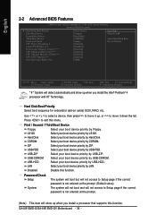
...ZIP Select your boot device priority by USB-ZIP. Disabled Disable this menu. English 2-2 Advanced BIOS Features CMOS Setup Utility-Copyright (C) 1984-2005 Award Software Advanced BIOS Features ` Hard Disk Boot Priority First Boot Device Second Boot Device Third Boot Device Password Check...you install the Intel® Pentium® 4 processor with HT Technology. USB-FDD Select your boot device priority by USB-FDD. GA-8I915MD-G/GA-8I915MD-GV Motherboard - 36 - LAN Select your boot device priority by LAN. First / Second / Third Boot Device Floppy Select your boot...
...ZIP Select your boot device priority by USB-ZIP. Disabled Disable this menu. English 2-2 Advanced BIOS Features CMOS Setup Utility-Copyright (C) 1984-2005 Award Software Advanced BIOS Features ` Hard Disk Boot Priority First Boot Device Second Boot Device Third Boot Device Password Check...you install the Intel® Pentium® 4 processor with HT Technology. USB-FDD Select your boot device priority by USB-FDD. GA-8I915MD-G/GA-8I915MD-GV Motherboard - 36 - LAN Select your boot device priority by LAN. First / Second / Third Boot Device Floppy Select your boot...

Manual
Page 37
... windows XP.(Default value) No-Execute Memory Protect (Note) Enabled Enable No-Execute Memory Protect function.(Default value) Disabled Disable No-Execute Memory Protect function. BIOS Setup CPU Enhanced Halt (C1E) (Note) Enabled Enable CPU Enhanced Halt (C1E) function.(Default value) Disabled Disable CPU Enhanced Halt (C1E) function. Limit CPUID Max...
... windows XP.(Default value) No-Execute Memory Protect (Note) Enabled Enable No-Execute Memory Protect function.(Default value) Disabled Disable No-Execute Memory Protect function. BIOS Setup CPU Enhanced Halt (C1E) (Note) Enabled Enable CPU Enhanced Halt (C1E) function.(Default value) Disabled Disable CPU Enhanced Halt (C1E) function. Limit CPUID Max...
Manual
Page 38
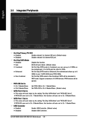
... Peripherals On-Chip Primary PCI IDE On-Chip SATA Mode x PATA IDE Set to SATA Port 0 Set to SATA Port 1 Set to Ch. 1 Master/Slave. BIOS will auto detect. (Default value) Set On-Chip SATA mode to ". GA-8I915MD-G/GA-8I915MD-GV Motherboard - 38 -
... Peripherals On-Chip Primary PCI IDE On-Chip SATA Mode x PATA IDE Set to SATA Port 0 Set to SATA Port 1 Set to Ch. 1 Master/Slave. BIOS will auto detect. (Default value) Set On-Chip SATA mode to ". GA-8I915MD-G/GA-8I915MD-GV Motherboard - 38 -


