Manual
Page 5
... the CPU 14 1-3-2 Installation of the Heatsink 15 1-4 Installation of Memory 16 1-5 Installation of Expansion Cards 18 1-5-1 Graphics Card Support List 18 1-6 I/O Back Panel Introduction 20 1-7 Connectors Introduction 21 Chapter 2 BIOS Setup 31 The Main Menu (For example: BIOS Ver. : GA-8I915MD-G F3a 32 2-1 Standard CMOS Features 34 2-2 Advanced BIOS Features 36 2-3 IntegratedPeripherals 38 2-4 Power Management Setup 40 2-5 PnP/PCI Configurations 41 2-6 PC Health Status 42 2-7 Frequency/Voltage Control 44 2-8 Load Fail-Safe Defaults 45 2-9 Load Optimized Defaults 45 2-10 Set...
... the CPU 14 1-3-2 Installation of the Heatsink 15 1-4 Installation of Memory 16 1-5 Installation of Expansion Cards 18 1-5-1 Graphics Card Support List 18 1-6 I/O Back Panel Introduction 20 1-7 Connectors Introduction 21 Chapter 2 BIOS Setup 31 The Main Menu (For example: BIOS Ver. : GA-8I915MD-G F3a 32 2-1 Standard CMOS Features 34 2-2 Advanced BIOS Features 36 2-3 IntegratedPeripherals 38 2-4 Power Management Setup 40 2-5 PnP/PCI Configurations 41 2-6 PC Health Status 42 2-7 Frequency/Voltage Control 44 2-8 Load Fail-Safe Defaults 45 2-9 Load Optimized Defaults 45 2-10 Set...
Manual
Page 12
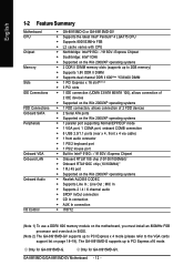
... processor and overclock in Intel® 915G / 915GV Express Chipset Š Onboard RTL8110S chip (10/100/1000Mbit) Š Onboard RTL8100C chip (10/100Mbit) Š 1 RJ 45 port Š Supported on page 18~19). Only for GA-8I915MD-GV. The GA-8I915MD-G supports up to PCI Express x 4 mode (please refer to PCI Express x16 mode. Line Out ; Only for GA-8I915MD-G. GA-8I915MD-G/GA-8I915MD-GV Motherboard - 12 - English 1-2 Feature Summary Motherboard CPU Chipset Memory Slots IDE Connections FDD Connections Onboard SATA Peripherals Onboard VGA Onboard LAN Onboard Audio I/O Control...
... processor and overclock in Intel® 915G / 915GV Express Chipset Š Onboard RTL8110S chip (10/100/1000Mbit) Š Onboard RTL8100C chip (10/100Mbit) Š 1 RJ 45 port Š Supported on page 18~19). Only for GA-8I915MD-GV. The GA-8I915MD-G supports up to PCI Express x 4 mode (please refer to PCI Express x16 mode. Line Out ; Only for GA-8I915MD-G. GA-8I915MD-G/GA-8I915MD-GV Motherboard - 12 - English 1-2 Feature Summary Motherboard CPU Chipset Memory Slots IDE Connections FDD Connections Onboard SATA Peripherals Onboard VGA Onboard LAN Onboard Audio I/O Control...
Manual
Page 14
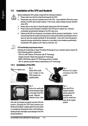
... that the system bus frequency be set the CPU host frequency in a straight and downwards motion. Fig. 3 Notice the small gold colored triangle located on the CPU socket to the CPU during installation.) GA-8I915MD-G/GA-8I915MD-GV Motherboard - 14 - Please add an even layer of heat sink paste between your computer system requires all of the CPU and Heatsink Before installing the CPU, please comply with the processor specifications. Align the...
... that the system bus frequency be set the CPU host frequency in a straight and downwards motion. Fig. 3 Notice the small gold colored triangle located on the CPU socket to the CPU during installation.) GA-8I915MD-G/GA-8I915MD-GV Motherboard - 14 - Please add an even layer of heat sink paste between your computer system requires all of the CPU and Heatsink Before installing the CPU, please comply with the processor specifications. Align the...

Manual
Page 17
... the Dual Channel Technology, please note the following explanations due to use memory modules of Intel chipset specifications. 1. Dual Channel mode will add double. To enable Dual Channel mode, please insert two DDR II memory modules (it is installed. 2. English Dual Channel Memory Configuration The GA-8I915MD-G/GA-8I915MD-GV supports the Dual Channel Technology. After operating the Dual Channel Technology, the bandwidth of Memory Bus will not be enabled if only one DDR II memory module is recommended to the limitation of identical brand, size, chips, and speed...
... the Dual Channel Technology, please note the following explanations due to use memory modules of Intel chipset specifications. 1. Dual Channel mode will add double. To enable Dual Channel mode, please insert two DDR II memory modules (it is installed. 2. English Dual Channel Memory Configuration The GA-8I915MD-G/GA-8I915MD-GV supports the Dual Channel Technology. After operating the Dual Channel Technology, the bandwidth of Memory Bus will not be enabled if only one DDR II memory module is recommended to the limitation of identical brand, size, chips, and speed...
Manual
Page 18
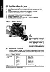
... slot. 5. PCI Express x16 Cards Graphics Chip Nvidia Maker Gigabyte Gigabyte Gigabyte Gigabyte Gigabyte Gigabyte Model Name GV-NX53128D GV-NX57128D GV-NX59128D GV-NX62128D GV-NX66256D GV-NX66T128VP "*" Only for the add-on the computer, if necessary, setup BIOS utility of Expansion Cards You can install your computer's chassis cover. 7. Power on graphics card.) Figure 1-1. English 1-5 Installation of expansion card from BIOS. 8. Read the related expansion card's instruction document before installing the driver for GA-8I915MD-GV. When you try uninstall the VGA card...
... slot. 5. PCI Express x16 Cards Graphics Chip Nvidia Maker Gigabyte Gigabyte Gigabyte Gigabyte Gigabyte Gigabyte Model Name GV-NX53128D GV-NX57128D GV-NX59128D GV-NX62128D GV-NX66256D GV-NX66T128VP "*" Only for the add-on the computer, if necessary, setup BIOS utility of Expansion Cards You can install your computer's chassis cover. 7. Power on graphics card.) Figure 1-1. English 1-5 Installation of expansion card from BIOS. 8. Read the related expansion card's instruction document before installing the driver for GA-8I915MD-GV. When you try uninstall the VGA card...
Manual
Page 24
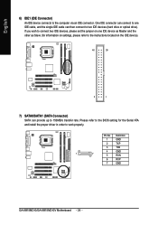
... 7 GND GA-8I915MD-G/GA-8I915MD-GV Motherboard - 24 - One IDE connector can connect to one IDE device as Master and the other as Slave (for the Serial ATA and install the proper driver in order to two IDE devices (hard drive or optical drive). Please refer to the BIOS setting for information on settings, please refer to the instructions located on one IDE cable, and the single IDE cable can provide up to the computer via an IDE connector. Pin No...
... 7 GND GA-8I915MD-G/GA-8I915MD-GV Motherboard - 24 - One IDE connector can connect to one IDE device as Master and the other as Slave (for the Serial ATA and install the proper driver in order to two IDE devices (hard drive or optical drive). Please refer to the BIOS setting for information on settings, please refer to the instructions located on one IDE cable, and the single IDE cable can provide up to the computer via an IDE connector. Pin No...
Manual
Page 26
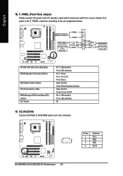
... (Power Switch) (Red) MSG(Message LED/Power/Sleep LED) (Yellow) NC ( Purple) Pin 1: LED anode(+) Pin 2: LED cathode(-) Pin 1: Power Pin 2- Pin No. Pin 3: NC Pin 4: Data(-) Open: Normal Close: Reset Hardware System Open: Normal Close: Power On/Off Pin 1: LED anode(+) Pin 2: LED cathode(-) NC 11) CD_IN (CD IN) Connect CD-ROM or DVD-ROM audio out to the pin assignment below. Speaker Connector Power Switch Message LED/ Power/ Sleep LED SPEAK- 20 19 SPEAK+ PWPW+ MSGMSG+ 21 NCRES+ RES- Definition 1 CD-L 1 2 GND 3 GND 4 CD-R GA-8I915MD-G/GA-8I915MD-GV Motherboard...
... (Power Switch) (Red) MSG(Message LED/Power/Sleep LED) (Yellow) NC ( Purple) Pin 1: LED anode(+) Pin 2: LED cathode(-) Pin 1: Power Pin 2- Pin No. Pin 3: NC Pin 4: Data(-) Open: Normal Close: Reset Hardware System Open: Normal Close: Power On/Off Pin 1: LED anode(+) Pin 2: LED cathode(-) NC 11) CD_IN (CD IN) Connect CD-ROM or DVD-ROM audio out to the pin assignment below. Speaker Connector Power Switch Message LED/ Power/ Sleep LED SPEAK- 20 19 SPEAK+ PWPW+ MSGMSG+ 21 NCRES+ RES- Definition 1 CD-L 1 2 GND 3 GND 4 CD-R GA-8I915MD-G/GA-8I915MD-GV Motherboard...
Manual
Page 32
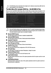
...-2005 Award Software ` Standard CMOS Features ` Advanced BIOS Features ` Integrated Peripherals ` Power Management Setup ` PnP/PCI Configurations ` PC Health Status ` Frequency/Voltage Control ESC: Quit F8: Q-Flash Load Fail-Safe Defaults Load Optimized Defaults Set Supervisor Password Set User Password Save & Exit Setup Exit Without Saving KLJI: Select Item F10: Save & Exit Setup Time, Date, Hard Disk Type... GA-8I915MD-G/GA-8I915MD-GV Motherboard - 32 - If you can't find the setting you enter Award BIOS CMOS Setup Utility, the Main Menu (as usual. This action makes the system reset to...
...-2005 Award Software ` Standard CMOS Features ` Advanced BIOS Features ` Integrated Peripherals ` Power Management Setup ` PnP/PCI Configurations ` PC Health Status ` Frequency/Voltage Control ESC: Quit F8: Q-Flash Load Fail-Safe Defaults Load Optimized Defaults Set Supervisor Password Set User Password Save & Exit Setup Exit Without Saving KLJI: Select Item F10: Save & Exit Setup Time, Date, Hard Disk Type... GA-8I915MD-G/GA-8I915MD-GV Motherboard - 32 - If you can't find the setting you enter Award BIOS CMOS Setup Utility, the Main Menu (as usual. This action makes the system reset to...

Manual
Page 34
.../Auto(default:Auto) Capacity Capacity of currently installed hard disk. The two options are : CHS/LBA/Large/Auto(default:Auto) Capacity Capacity of currently installed hard disk. English 2-1 Standard CMOS Features CMOS Setup Utility-Copyright (C) 1984-2005 Award Software Standard CMOS Features Date (mm:dd:yy) Time (hh:mm:ss) Wed, Oct 27 2005 22:31:24 Item Help Menu Level` ` IDE Channel 0 Master ` IDE Channel 0 Slave ` IDE Channel 2 Master ` IDE Channel 3 Master Drive A Drive B Floppy 3 Mode Support [None] [None] [None] [None] [1.44M, 3.5"] [None] [Disabled] Change...
.../Auto(default:Auto) Capacity Capacity of currently installed hard disk. The two options are : CHS/LBA/Large/Auto(default:Auto) Capacity Capacity of currently installed hard disk. English 2-1 Standard CMOS Features CMOS Setup Utility-Copyright (C) 1984-2005 Award Software Standard CMOS Features Date (mm:dd:yy) Time (hh:mm:ss) Wed, Oct 27 2005 22:31:24 Item Help Menu Level` ` IDE Channel 0 Master ` IDE Channel 0 Slave ` IDE Channel 2 Master ` IDE Channel 3 Master Drive A Drive B Floppy 3 Mode Support [None] [None] [None] [None] [1.44M, 3.5"] [None] [Disabled] Change...
Manual
Page 43
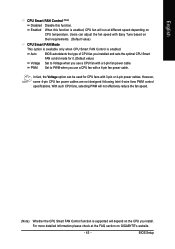
.... (Default value) CPU Smart FAN Mode This option is available only when CPU Smart FAN Control is enabled. In fact, the Voltage option can adjust the fan speed with a 3-pin fan power cable. With such CPU fans, selecting PWM will not effectively reduce the fan speed. (Note) Whether the CPU Smart FAN Control function is supported will run at the FAQ section on GIGABYTE's website. - 43 - BIOS Setup English CPU Smart FAN Control (Note) Disabled Enabled Disable this function is enabled, CPU fan will depend on the CPU you use a CPU fan with 3-pin or 4-pin power cables. PWM Set...
.... (Default value) CPU Smart FAN Mode This option is available only when CPU Smart FAN Control is enabled. In fact, the Voltage option can adjust the fan speed with a 3-pin fan power cable. With such CPU fans, selecting PWM will not effectively reduce the fan speed. (Note) Whether the CPU Smart FAN Control function is supported will run at the FAQ section on GIGABYTE's website. - 43 - BIOS Setup English CPU Smart FAN Control (Note) Disabled Enabled Disable this function is enabled, CPU fan will depend on the CPU you use a CPU fan with 3-pin or 4-pin power cables. PWM Set...

Manual
Page 46
... a password. The BIOS Setup program allows you are prompted to enter password. English 2-10 Set Supervisor/User Password CMOS Setup Utility-Copyright (C) 1984-2005 Award Software ` Standard CMOS Features ` Advanced BIOS Features ` Integrated Peripherals ` Power Management Setup ` PnP/PCI ConfiguratioEnsnter Password: ` PC Health Status ` Frequency/Voltage Control Load Fail-Safe Defaults Load Optimized Defaults Set Supervisor Password Set User Password Save & Exit Setup Exit Without Saving Esc: Quit F8: Q-Flash KLJI: Select Item F10: Save & Exit Setup Change/Set/Disable Password...
... a password. The BIOS Setup program allows you are prompted to enter password. English 2-10 Set Supervisor/User Password CMOS Setup Utility-Copyright (C) 1984-2005 Award Software ` Standard CMOS Features ` Advanced BIOS Features ` Integrated Peripherals ` Power Management Setup ` PnP/PCI ConfiguratioEnsnter Password: ` PC Health Status ` Frequency/Voltage Control Load Fail-Safe Defaults Load Optimized Defaults Set Supervisor Password Set User Password Save & Exit Setup Exit Without Saving Esc: Quit F8: Q-Flash KLJI: Select Item F10: Save & Exit Setup Change/Set/Disable Password...

Manual
Page 53
... Software Utilities (Not all model support these Unique Software Utilities, please check your MB features.) U-PLUS D.P.S. (Universal Plus Dual Power System) The U-Plus Dual Power System (U-Plus DPS) is designed especially to maximize memory performance and boost memory bandwidth up the PC chassis and short-circuit the "Clear CMOS" pins or the battery on the motherboard to reset the system back to factory default settings. automatically resets the overclocked system settings back to be monitored and controlled...
... Software Utilities (Not all model support these Unique Software Utilities, please check your MB features.) U-PLUS D.P.S. (Universal Plus Dual Power System) The U-Plus Dual Power System (U-Plus DPS) is designed especially to maximize memory performance and boost memory bandwidth up the PC chassis and short-circuit the "Clear CMOS" pins or the battery on the motherboard to reset the system back to factory default settings. automatically resets the overclocked system settings back to be monitored and controlled...
Manual
Page 54
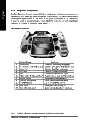
...screen Display panel of both CPU cooling fan and North-Bridge Chipset cooling fan, 4) PC health for enhancing system performance, 2) C.I.A. C.I.A./C.I.A.2 and M.I.B./M.I.B.2 Enters the C.I.A./2 and M.I .B. GO Confirmation and Execution button 6. and M.I .B./2 setting page 3. Help button Display EasyTuneTM 5 Help file 11. GA-8I915MD-G/GA-8I915MD-GV Motherboard - 54 - Featuring several powerful yet easy to GIGABYTE website 10. for special enhancement for CPU and Memory, 3) Smart-Fan control for managing fan speed control of CPU frequency 8. Smart-Fan Enters the Smart...
...screen Display panel of both CPU cooling fan and North-Bridge Chipset cooling fan, 4) PC health for enhancing system performance, 2) C.I.A. C.I.A./C.I.A.2 and M.I.B./M.I.B.2 Enters the C.I.A./2 and M.I .B. GO Confirmation and Execution button 6. and M.I .B./2 setting page 3. Help button Display EasyTuneTM 5 Help file 11. GA-8I915MD-G/GA-8I915MD-GV Motherboard - 54 - Featuring several powerful yet easy to GIGABYTE website 10. for special enhancement for CPU and Memory, 3) Smart-Fan control for managing fan speed control of CPU frequency 8. Smart-Fan Enters the Smart...

Manual
Page 55
... during system power-on PATA and SATA IDE controllers. Press any key to startup XpressRecovery2..... VESA-supported VGA cards How to enter Xpress Recovery2. Upon system restart, the message which says "Boot from CD-ROM and subsequent access by pressing the key in the future. 2. Boot from CD/DVD: Press any key to use the Xpress Recovery2 Initial access by booting from CD/DVD:" will appear in your CD-ROM drive. Appendix...
... during system power-on PATA and SATA IDE controllers. Press any key to startup XpressRecovery2..... VESA-supported VGA cards How to enter Xpress Recovery2. Upon system restart, the message which says "Boot from CD-ROM and subsequent access by pressing the key in the future. 2. Boot from CD/DVD: Press any key to use the Xpress Recovery2 Initial access by booting from CD/DVD:" will appear in your CD-ROM drive. Appendix...
Manual
Page 58
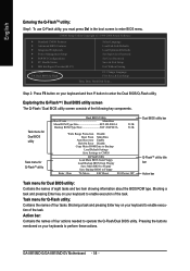
... ROM Type/Size SST 49LF003A 512K 512K Wide Range Protection Disable Boot From Main Bios Auto Recovery Enable Halt On Error Disable Copy Main ROM Data to Backup Load Default Settings Save Settings to CMOS Q-Flash Utility Load Main BIOS from Floppy Load Backup BIOS from Floppy Save Main BIOS to Floppy Save Backup BIOS to Floppy Enter : Run :Move ESC:Reset F10:Power Off Dual BIOS utility bar Q-FlashTM utility title bar Action bar Task menu for Q-Flash utility: Contains the names of four actions needed to enter the Dual BIOS/Q-Flash utility. GA-8I915MD-G/GA-8I915MD-GV Motherboard...
... ROM Type/Size SST 49LF003A 512K 512K Wide Range Protection Disable Boot From Main Bios Auto Recovery Enable Halt On Error Disable Copy Main ROM Data to Backup Load Default Settings Save Settings to CMOS Q-Flash Utility Load Main BIOS from Floppy Load Backup BIOS from Floppy Save Main BIOS to Floppy Save Backup BIOS to Floppy Enter : Run :Move ESC:Reset F10:Power Off Dual BIOS utility bar Q-FlashTM utility title bar Action bar Task menu for Q-Flash utility: Contains the names of four actions needed to enter the Dual BIOS/Q-Flash utility. GA-8I915MD-G/GA-8I915MD-GV Motherboard...
Manual
Page 60
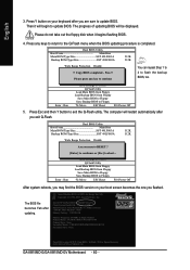
... the floppy disk when it will begin to exit the Q-Flash utility. Pass !! Press Esc and then Y button to update BIOS. Load Default Settings Save Settings to CMOS Q-Flash Utility Load Main BIOS from Floppy Load Backup BIOS from Floppy Save Main BIOS to Floppy Save Backup BIOS to Floppy Enter : Run :Move ESC:Reset F10:Power Off You can repeat Step 1 to 4 to flash the backup BIOS, too. 5. uCtopRyecBoIvOeSrycomEnpalebtled - The BIOS file becomes Fab after you exit Q-Flash. Dual BIOS Utility Boot From Main Bios Main ROM Type/Size SST 49LF003A Backup ROM Type/Size SST...
... the floppy disk when it will begin to exit the Q-Flash utility. Pass !! Press Esc and then Y button to update BIOS. Load Default Settings Save Settings to CMOS Q-Flash Utility Load Main BIOS from Floppy Load Backup BIOS from Floppy Save Main BIOS to Floppy Save Backup BIOS to Floppy Enter : Run :Move ESC:Reset F10:Power Off You can repeat Step 1 to 4 to flash the backup BIOS, too. 5. uCtopRyecBoIvOeSrycomEnpalebtled - The BIOS file becomes Fab after you exit Q-Flash. Dual BIOS Utility Boot From Main Bios Main ROM Type/Size SST 49LF003A Backup ROM Type/Size SST...

Manual
Page 61
...)u?pYervisor Password PnP/PCI Configurations Set User Password PC Health Status Save & Exit Setup MB Intelligent Tweaker(M.I.T.) Exit Without Saving ESC: Quit F8: Dual BIOS/Q-Flash F3: Change Language F10: Save & Exit Setup Time, Date, Hard Disk Type... The procedure is completed. Appendix English 6. Select Save & Exit Setup item to save the settings to save and exit. Press Y on Single-BIOS Motherboards. Part Two: Updating BIOS with Q-FlashTM Utility on your keyboard to load BIOS Fail-Safe Defaults...
...)u?pYervisor Password PnP/PCI Configurations Set User Password PC Health Status Save & Exit Setup MB Intelligent Tweaker(M.I.T.) Exit Without Saving ESC: Quit F8: Dual BIOS/Q-Flash F3: Change Language F10: Save & Exit Setup Time, Date, Hard Disk Type... The procedure is completed. Appendix English 6. Select Save & Exit Setup item to save the settings to save and exit. Press Y on Single-BIOS Motherboards. Part Two: Updating BIOS with Q-FlashTM Utility on your keyboard to load BIOS Fail-Safe Defaults...
Manual
Page 64
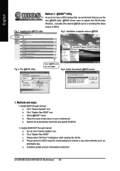
....E2). GA-8I915MD-G/GA-8I915MD-GV Motherboard - 64 - Installation complete and run @BIOS Click Start/ Programs/ GIGABYTE/@BIOS Fig 3. Click "Update New BIOS" icon c. Click "Update New BIOS" c. d. Click "Internet Update" icon b. System will automatically download and update the BIOS. The @BIOS utility Select @BIOS item, and click Install. Update BIOS through Internet: a. English Method 2 : @BIOSTM Utility If you do not have a DOS startup disk, we recommend that you use the new @BIOS utility. @BIOS allows users to download the latest version of BIOS. Just...
....E2). GA-8I915MD-G/GA-8I915MD-GV Motherboard - 64 - Installation complete and run @BIOS Click Start/ Programs/ GIGABYTE/@BIOS Fig 3. Click "Update New BIOS" icon c. Click "Update New BIOS" c. d. Click "Internet Update" icon b. System will automatically download and update the BIOS. The @BIOS utility Select @BIOS item, and click Install. Update BIOS through Internet: a. English Method 2 : @BIOSTM Utility If you do not have a DOS startup disk, we recommend that you use the new @BIOS utility. @BIOS allows users to download the latest version of BIOS. Just...

Manual
Page 66
Line Out STEP 2: After installing the audio driver, you use speakers with amplifier to get the best sound effect if the stereo output is applied. GA-8I915MD-G/GA-8I915MD-GV Motherboard - 66 - Click the icon to "Line Out." STEP 1: Connect the stereo speakers or earphone to select the function. English 4-1-4 2 / 4 / 6 Channel Audio Function Introduction 2 Channel Audio Setup We recommend that you 'll find a Sound Effect icon on the lower right hand...
Line Out STEP 2: After installing the audio driver, you use speakers with amplifier to get the best sound effect if the stereo output is applied. GA-8I915MD-G/GA-8I915MD-GV Motherboard - 66 - Click the icon to "Line Out." STEP 1: Connect the stereo speakers or earphone to select the function. English 4-1-4 2 / 4 / 6 Channel Audio Function Introduction 2 Channel Audio Setup We recommend that you 'll find a Sound Effect icon on the lower right hand...
Manual
Page 72
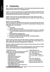
... light of my keyboard/optical mouse still on after entering BIOS menu and you will be able to the steps below may help you can use a metal object to connect the positive and negative pins in the manual. If your board has a Clear CMOS jumper, please refer to enter BIOS and load Fail-Safe Defaults(or load Optimized Defaults). 7. Take out the battery gently and put it aside for beep code 8, these options. Save changes...
... light of my keyboard/optical mouse still on after entering BIOS menu and you will be able to the steps below may help you can use a metal object to connect the positive and negative pins in the manual. If your board has a Clear CMOS jumper, please refer to enter BIOS and load Fail-Safe Defaults(or load Optimized Defaults). 7. Take out the battery gently and put it aside for beep code 8, these options. Save changes...


