Manual
Page 6
Chapter 3 Drivers Installation 49 3-1 Install Chipset Drivers 49 3-2 SoftwareApplications 50 3-3 Driver CD Information 50 3-4 Hardware Information 51 3-5 Contact Us ...51 Chapter 4 Appendix 53 4-1 Unique Software Utilities 53 4-1-1 EasyTune 5 Introduction 54 4-1-2 Xpress Recovery2 Introduction 55 4-1-3 Flash BIOS Method Introduction 57 4-1-4 2 / 4 / 6 Channel Audio Function Introduction 66 4-2 Troubleshooting 72 - 6 -
Chapter 3 Drivers Installation 49 3-1 Install Chipset Drivers 49 3-2 SoftwareApplications 50 3-3 Driver CD Information 50 3-4 Hardware Information 51 3-5 Contact Us ...51 Chapter 4 Appendix 53 4-1 Unique Software Utilities 53 4-1-1 EasyTune 5 Introduction 54 4-1-2 Xpress Recovery2 Introduction 55 4-1-3 Flash BIOS Method Introduction 57 4-1-4 2 / 4 / 6 Channel Audio Function Introduction 66 4-2 Troubleshooting 72 - 6 -
Manual
Page 7
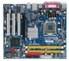
Only for GA-8I915MD-G. GA-8I915MD-G / GA-8I915MD-GV Motherboard Layout KB_MS ATX_12V LGA775 CPU_FAN ATX CI IDE1 IT8712 COMA GA-8I915MD-G or GA-8I915MD-GV LPT LAN VGA USB DDRII2 PWR_LED F_PANEL USB AUDIO Intel 915G / Intel 915GV PCIE_16 RTL8110S / RTL8100C CD_IN CODEC AUX_IN F_AUDIO SUR_CEN SPDIF_IO COMB PCI1 PCI2 Intel ICH6 PCI3 SYS_FAN F_USB1 F_USB2 DDRII1 FDD SATA1 SATA0 BIOS BAT CLR_CMOS Only for GA-8I915MD-GV. - 7 -
Only for GA-8I915MD-G. GA-8I915MD-G / GA-8I915MD-GV Motherboard Layout KB_MS ATX_12V LGA775 CPU_FAN ATX CI IDE1 IT8712 COMA GA-8I915MD-G or GA-8I915MD-GV LPT LAN VGA USB DDRII2 PWR_LED F_PANEL USB AUDIO Intel 915G / Intel 915GV PCIE_16 RTL8110S / RTL8100C CD_IN CODEC AUX_IN F_AUDIO SUR_CEN SPDIF_IO COMB PCI1 PCI2 Intel ICH6 PCI3 SYS_FAN F_USB1 F_USB2 DDRII1 FDD SATA1 SATA0 BIOS BAT CLR_CMOS Only for GA-8I915MD-GV. - 7 -
Manual
Page 12
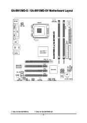
... 1-2 Feature Summary Motherboard CPU Chipset Memory Slots IDE Connections FDD Connections Onboard SATA Peripherals Onboard VGA Onboard LAN Onboard Audio I/O Control Š GA-8I915MD-G or GA-8I915MD-GV Š Supports the latest Intel® Pentium® 4 LGA775 CPU Š Supports 800/533MHz FSB Š L2... support list on the Win 2000/XP operating systems Š Realtek ALC655 CODEC Š Supports Line In ; Only for GA-8I915MD-GV. MIC In Š Supports 2 / 4 / 6 channel audio Š SPDIF In/Out connection Š CD In connection Š AUX In connection Š IT8712 (Note 1) To...
... 1-2 Feature Summary Motherboard CPU Chipset Memory Slots IDE Connections FDD Connections Onboard SATA Peripherals Onboard VGA Onboard LAN Onboard Audio I/O Control Š GA-8I915MD-G or GA-8I915MD-GV Š Supports the latest Intel® Pentium® 4 LGA775 CPU Š Supports 800/533MHz FSB Š L2... support list on the Win 2000/XP operating systems Š Realtek ALC655 CODEC Š Supports Line In ; Only for GA-8I915MD-GV. MIC In Š Supports 2 / 4 / 6 channel audio Š SPDIF In/Out connection Š CD In connection Š AUX In connection Š IT8712 (Note 1) To...
Manual
Page 20
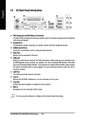
... can be connected to this connector. GA-8I915MD-G/GA-8I915MD-GV Motherboard - 20 - LAN Port The LAN port provides Internet connection. If your device(s) such as USB keyboard, mouse, scanner, zip, speaker...etc. You can be connected to configure 2-/4-/6-channel audio functioning. USB port Before you connect ...port allows connection of a printer, scanner and other peripheral devices. COMA (Serial Port) Connects to Line In jack. can use audio software to MIC In jack. Also make sure your OS does not support USB controller, please contact OS vendor for possible patch...
... can be connected to this connector. GA-8I915MD-G/GA-8I915MD-GV Motherboard - 20 - LAN Port The LAN port provides Internet connection. If your device(s) such as USB keyboard, mouse, scanner, zip, speaker...etc. You can be connected to configure 2-/4-/6-channel audio functioning. USB port Before you connect ...port allows connection of a printer, scanner and other peripheral devices. COMA (Serial Port) Connects to Line In jack. can use audio software to MIC In jack. Also make sure your OS does not support USB controller, please contact OS vendor for possible patch...
Manual
Page 25
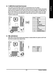
...MPD- - 25 - Please note, you can have front audio connector. English 8) F_AUDIO (Front Audio Panel Connector) If you want to use Front Audio connector, you must have the alternative of using front audio connector or of using rear audio connector to play sound. 2 10 1 9 Pin No. ... 8 9 10 Definition MIC GND MIC_BIAS Power Front Audio (R) Rear Audio (R)/ Return R NC No Pin Front Audio (L) Rear Audio (L)/ Return L 9) PWR_LED (Optional) PWR_LED is connect with the system power indicator to utilize the front audio header, your dealer. Hardware Installation Also please make sure...
...MPD- - 25 - Please note, you can have front audio connector. English 8) F_AUDIO (Front Audio Panel Connector) If you want to use Front Audio connector, you must have the alternative of using front audio connector or of using rear audio connector to play sound. 2 10 1 9 Pin No. ... 8 9 10 Definition MIC GND MIC_BIAS Power Front Audio (R) Rear Audio (R)/ Return R NC No Pin Front Audio (L) Rear Audio (L)/ Return L 9) PWR_LED (Optional) PWR_LED is connect with the system power indicator to utilize the front audio header, your dealer. Hardware Installation Also please make sure...
Manual
Page 26
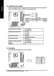
...Normal Close: Power On/Off Pin 1: LED anode(+) Pin 2: LED cathode(-) NC 11) CD_IN (CD IN) Connect CD-ROM or DVD-ROM audio out to the pin assignment below. HDHD+ Reset Switch IDE Hard Disk Active LED HD (IDE Hard Disk Active LED) (Blue) SPEAK (Speaker ...LED/Power/Sleep LED) (Yellow) NC ( Purple) Pin 1: LED anode(+) Pin 2: LED cathode(-) Pin 1: Power Pin 2- Definition 1 CD-L 1 2 GND 3 GND 4 CD-R GA-8I915MD-G/GA-8I915MD-GV Motherboard - 26 - English 10) F_PANEL (Front Panel Jumper) Please connect the power LED, PC speaker, reset switch and power switch etc of your chassis front...
...Normal Close: Power On/Off Pin 1: LED anode(+) Pin 2: LED cathode(-) NC 11) CD_IN (CD IN) Connect CD-ROM or DVD-ROM audio out to the pin assignment below. HDHD+ Reset Switch IDE Hard Disk Active LED HD (IDE Hard Disk Active LED) (Blue) SPEAK (Speaker ...LED/Power/Sleep LED) (Yellow) NC ( Purple) Pin 1: LED anode(+) Pin 2: LED cathode(-) Pin 1: Power Pin 2- Definition 1 CD-L 1 2 GND 3 GND 4 CD-R GA-8I915MD-G/GA-8I915MD-GV Motherboard - 26 - English 10) F_PANEL (Front Panel Jumper) Please connect the power LED, PC speaker, reset switch and power switch etc of your chassis front...
Manual
Page 27
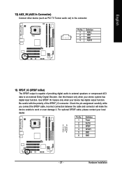
... 4 AUX-R 13) SPDIF_IO (SPDIF In/Out) The SPDIF output is capable of the SPDIF_IO connector. Be careful with the polarity of providing digital audio to external speakers or compressed AC3 data to the connector. Use SPDIF IN feature only when your stereo system has digital input function. English 12...) AUX_IN (AUX In Connector) Connect other device (such as PCI TV Tunner audio out) to an external Dolby Digital Decoder. Use this feature only when your device has digital output function. Check the pin assignment ...
... 4 AUX-R 13) SPDIF_IO (SPDIF In/Out) The SPDIF output is capable of the SPDIF_IO connector. Be careful with the polarity of providing digital audio to external speakers or compressed AC3 data to the connector. Use SPDIF IN feature only when your stereo system has digital input function. English 12...) AUX_IN (AUX In Connector) Connect other device (such as PCI TV Tunner audio out) to an external Dolby Digital Decoder. Use this feature only when your device has digital output function. Check the pin assignment ...
Manual
Page 38
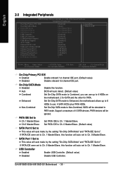
...PATA IDE Set to Ch.1 Master/Slave Ch.0 Master/Slave Set PATA IDE to USB Controller USB 2.0 Controller USB Keyboard Support USB Mouse Support AC97 Audio Onboard H/W LAN OnBoard LAN Boot ROM Onboard Serial Port 1 Onboard Serial Port 2 Onboard Parallel Port Parallel Port Mode x ECP Mode Use DMA [...1st channel IDE port. If PATA IDE were set to Ch. 1 Master/Slave, this function will be ignored. Support a maximum of 4 SATA devices. GA-8I915MD-G/GA-8I915MD-GV Motherboard - 38 - Set On-Chip SATA mode to Enhanced, the motherboard allows up to 6 HDDs to use up to Ch. 0 Master/Slave, this...
...PATA IDE Set to Ch.1 Master/Slave Ch.0 Master/Slave Set PATA IDE to USB Controller USB 2.0 Controller USB Keyboard Support USB Mouse Support AC97 Audio Onboard H/W LAN OnBoard LAN Boot ROM Onboard Serial Port 1 Onboard Serial Port 2 Onboard Parallel Port Parallel Port Mode x ECP Mode Use DMA [...1st channel IDE port. If PATA IDE were set to Ch. 1 Master/Slave, this function will be ignored. Support a maximum of 4 SATA devices. GA-8I915MD-G/GA-8I915MD-GV Motherboard - 38 - Set On-Chip SATA mode to Enhanced, the motherboard allows up to 6 HDDs to use up to Ch. 0 Master/Slave, this...
Manual
Page 39
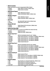
... Mouse Support Enabled Enable USB Mouse Support. Disabled Disable onboard Serial port 2. Disabled Disable USB Mouse Support. (Default value) AC97 Audio Auto Disabled Auto detect AC97 audio function. (Default value) Disable AC97 audio function. Parallel Port Mode SPP Using Parallel port as Standard Parallel Port. (Default value) EPP Using Parallel port as Extended...
... Mouse Support Enabled Enable USB Mouse Support. Disabled Disable onboard Serial port 2. Disabled Disable USB Mouse Support. (Default value) AC97 Audio Auto Disabled Auto detect AC97 audio function. (Default value) Disable AC97 audio function. Parallel Port Mode SPP Using Parallel port as Standard Parallel Port. (Default value) EPP Using Parallel port as Extended...

Manual
Page 66
... is applied. English 4-1-4 2 / 4 / 6 Channel Audio Function Introduction 2 Channel Audio Setup We recommend that you 'll find a Sound Effect icon on the lower right hand taskbar. Line Out STEP 2: After installing the audio driver, you use speakers with amplifier to "Line Out." ...Click the icon to select the function. STEP 3: On the AC97 Audio Configuration menu, click the Speaker Configuration tab and select the 2-channel mode for stereo speaker output check box. GA-8I915MD-G/GA-8I915MD-GV Motherboard - ...
... is applied. English 4-1-4 2 / 4 / 6 Channel Audio Function Introduction 2 Channel Audio Setup We recommend that you 'll find a Sound Effect icon on the lower right hand taskbar. Line Out STEP 2: After installing the audio driver, you use speakers with amplifier to "Line Out." ...Click the icon to select the function. STEP 3: On the AC97 Audio Configuration menu, click the Speaker Configuration tab and select the 2-channel mode for stereo speaker output check box. GA-8I915MD-G/GA-8I915MD-GV Motherboard - ...

Manual
Page 67
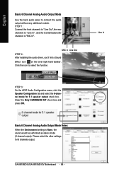
... the icon to "Line In." When the Environment setting is None, the sound would be performed as stereo mode (2-channel output). STEP 3: On the AC97 Audio Configuration menu, click the Speaker Configuration tab and select the 4-channel mode for 4-channel output. - 67 - Please select other settings (ex: Living Room) for... 4 speaker output check box. Line Out Line In Appendix English 4 Channel Analog Audio Output Mode STEP 1: Connect the front channels to "Line Out," the rear channels to select the function.
... the icon to "Line In." When the Environment setting is None, the sound would be performed as stereo mode (2-channel output). STEP 3: On the AC97 Audio Configuration menu, click the Speaker Configuration tab and select the 4-channel mode for 4-channel output. - 67 - Please select other settings (ex: Living Room) for... 4 speaker output check box. Line Out Line In Appendix English 4 Channel Analog Audio Output Mode STEP 1: Connect the front channels to "Line Out," the rear channels to select the function.
Manual
Page 68
... box and press OK. Basic 6 Channel Analog Audio Output Mode Notes: When the Environment setting is None, the sound would be performed as stereo mode (2-channel output). MIC In Line Out STEP 2: After installing the audio driver, you'll find a Sound Effect icon ...Please select the other settings for 5.1 speaker output check box. Click the icon to connect the audio output without any additional module. Line In GA-8I915MD-G/GA-8I915MD-GV Motherboard - 68 - STEP 3: On the AC97 Audio Configuration menu, click the Speaker Configuration tab and select the 6-channel mode for 6 channels output....
... box and press OK. Basic 6 Channel Analog Audio Output Mode Notes: When the Environment setting is None, the sound would be performed as stereo mode (2-channel output). MIC In Line Out STEP 2: After installing the audio driver, you'll find a Sound Effect icon ...Please select the other settings for 5.1 speaker output check box. Click the icon to connect the audio output without any additional module. Line In GA-8I915MD-G/GA-8I915MD-GV Motherboard - 68 - STEP 3: On the AC97 Audio Configuration menu, click the Speaker Configuration tab and select the 6-channel mode for 6 channels output....
Manual
Page 69
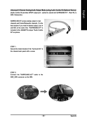
... the best solution if you need 6 channel output, Line In and MIC at the same time. It is included in the GIGABYTE unique "Audio Combo Kit" as picture. STEP 2: Connect the "SURROUND-KIT" cable to the chassis back panel with a screw. English Advanced 6 Channel Analog... Audio Output Mode (using Audio Combo Kit,Optional Device): (Audio Combo Kit provides SPDIF output port : optical & coaxial and SURROUND-KIT : Rear R/L & CEN /Subwoofer) SURROUND-KIT access analog ...
... the best solution if you need 6 channel output, Line In and MIC at the same time. It is included in the GIGABYTE unique "Audio Combo Kit" as picture. STEP 2: Connect the "SURROUND-KIT" cable to the chassis back panel with a screw. English Advanced 6 Channel Analog... Audio Output Mode (using Audio Combo Kit,Optional Device): (Audio Combo Kit provides SPDIF output port : optical & coaxial and SURROUND-KIT : Rear R/L & CEN /Subwoofer) SURROUND-KIT access analog ...

Manual
Page 70
... the other settings for 5.1 speaker output check box. Click the icon to SURROUND-KIT's SUB CENTER. GA-8I915MD-G/GA-8I915MD-GV Motherboard - 70 - STEP 4: After installing the audio driver, you'll find a Sound Effect icon on the lower right hand taskbar. Basic & Advanced 6 Channel Analog... Audio Output Mode Notes: When the Environment setting is None, the sound would be performed as stereo mode (2-channel output). STEP 5: On the AC97 Audio Configuration menu, click the Speaker Configuration tab and select the 6-channel...
... the other settings for 5.1 speaker output check box. Click the icon to SURROUND-KIT's SUB CENTER. GA-8I915MD-G/GA-8I915MD-GV Motherboard - 70 - STEP 4: After installing the audio driver, you'll find a Sound Effect icon on the lower right hand taskbar. Basic & Advanced 6 Channel Analog... Audio Output Mode Notes: When the Environment setting is None, the sound would be performed as stereo mode (2-channel output). STEP 5: On the AC97 Audio Configuration menu, click the Speaker Configuration tab and select the 6-channel...


